EP1857795A2 - Thermomètre auriculaire - Google Patents
Thermomètre auriculaire Download PDFInfo
- Publication number
- EP1857795A2 EP1857795A2 EP07009975A EP07009975A EP1857795A2 EP 1857795 A2 EP1857795 A2 EP 1857795A2 EP 07009975 A EP07009975 A EP 07009975A EP 07009975 A EP07009975 A EP 07009975A EP 1857795 A2 EP1857795 A2 EP 1857795A2
- Authority
- EP
- European Patent Office
- Prior art keywords
- sensor
- nozzle
- base
- thermometer
- set forth
- Prior art date
- Legal status (The legal status is an assumption and is not a legal conclusion. Google has not performed a legal analysis and makes no representation as to the accuracy of the status listed.)
- Granted
Links
Images


Classifications
-
- G—PHYSICS
- G01—MEASURING; TESTING
- G01J—MEASUREMENT OF INTENSITY, VELOCITY, SPECTRAL CONTENT, POLARISATION, PHASE OR PULSE CHARACTERISTICS OF INFRARED, VISIBLE OR ULTRAVIOLET LIGHT; COLORIMETRY; RADIATION PYROMETRY
- G01J5/00—Radiation pyrometry, e.g. infrared or optical thermometry
- G01J5/02—Constructional details
- G01J5/04—Casings
-
- G—PHYSICS
- G01—MEASURING; TESTING
- G01J—MEASUREMENT OF INTENSITY, VELOCITY, SPECTRAL CONTENT, POLARISATION, PHASE OR PULSE CHARACTERISTICS OF INFRARED, VISIBLE OR ULTRAVIOLET LIGHT; COLORIMETRY; RADIATION PYROMETRY
- G01J5/00—Radiation pyrometry, e.g. infrared or optical thermometry
- G01J5/02—Constructional details
- G01J5/0205—Mechanical elements; Supports for optical elements
-
- G—PHYSICS
- G01—MEASURING; TESTING
- G01J—MEASUREMENT OF INTENSITY, VELOCITY, SPECTRAL CONTENT, POLARISATION, PHASE OR PULSE CHARACTERISTICS OF INFRARED, VISIBLE OR ULTRAVIOLET LIGHT; COLORIMETRY; RADIATION PYROMETRY
- G01J5/00—Radiation pyrometry, e.g. infrared or optical thermometry
- G01J5/02—Constructional details
- G01J5/021—Probe covers for thermometers, e.g. tympanic thermometers; Containers for probe covers; Disposable probes
-
- G—PHYSICS
- G01—MEASURING; TESTING
- G01J—MEASUREMENT OF INTENSITY, VELOCITY, SPECTRAL CONTENT, POLARISATION, PHASE OR PULSE CHARACTERISTICS OF INFRARED, VISIBLE OR ULTRAVIOLET LIGHT; COLORIMETRY; RADIATION PYROMETRY
- G01J5/00—Radiation pyrometry, e.g. infrared or optical thermometry
- G01J5/02—Constructional details
- G01J5/04—Casings
- G01J5/049—Casings for tympanic thermometers
-
- G—PHYSICS
- G01—MEASURING; TESTING
- G01J—MEASUREMENT OF INTENSITY, VELOCITY, SPECTRAL CONTENT, POLARISATION, PHASE OR PULSE CHARACTERISTICS OF INFRARED, VISIBLE OR ULTRAVIOLET LIGHT; COLORIMETRY; RADIATION PYROMETRY
- G01J5/00—Radiation pyrometry, e.g. infrared or optical thermometry
- G01J5/02—Constructional details
- G01J5/05—Means for preventing contamination of the components of the optical system; Means for preventing obstruction of the radiation path
-
- G—PHYSICS
- G01—MEASURING; TESTING
- G01J—MEASUREMENT OF INTENSITY, VELOCITY, SPECTRAL CONTENT, POLARISATION, PHASE OR PULSE CHARACTERISTICS OF INFRARED, VISIBLE OR ULTRAVIOLET LIGHT; COLORIMETRY; RADIATION PYROMETRY
- G01J5/00—Radiation pyrometry, e.g. infrared or optical thermometry
- G01J5/02—Constructional details
- G01J5/06—Arrangements for eliminating effects of disturbing radiation; Arrangements for compensating changes in sensitivity
-
- G—PHYSICS
- G01—MEASURING; TESTING
- G01J—MEASUREMENT OF INTENSITY, VELOCITY, SPECTRAL CONTENT, POLARISATION, PHASE OR PULSE CHARACTERISTICS OF INFRARED, VISIBLE OR ULTRAVIOLET LIGHT; COLORIMETRY; RADIATION PYROMETRY
- G01J5/00—Radiation pyrometry, e.g. infrared or optical thermometry
- G01J5/10—Radiation pyrometry, e.g. infrared or optical thermometry using electric radiation detectors
- G01J5/12—Radiation pyrometry, e.g. infrared or optical thermometry using electric radiation detectors using thermoelectric elements, e.g. thermocouples
-
- G—PHYSICS
- G01—MEASURING; TESTING
- G01J—MEASUREMENT OF INTENSITY, VELOCITY, SPECTRAL CONTENT, POLARISATION, PHASE OR PULSE CHARACTERISTICS OF INFRARED, VISIBLE OR ULTRAVIOLET LIGHT; COLORIMETRY; RADIATION PYROMETRY
- G01J5/00—Radiation pyrometry, e.g. infrared or optical thermometry
- G01J5/70—Passive compensation of pyrometer measurements, e.g. using ambient temperature sensing or sensing of temperature within housing
Definitions
- the present disclosure generally relates to the field of biomedical thermometers, and more particularly, to a tympanic thermometer that includes a sensor having a nozzle disposed therewith that improves accuracy of temperature measurement.
- thermometers are typically employed to facilitate the prevention, diagnosis and treatment of diseases, body ailments, etc. for humans and other animals, as is known. Doctors, nurses, parents, care providers, etc. utilize thermometers to measure a subject's body temperature for detecting a fever, monitoring the subject's body temperature, etc. An accurate reading of a subject's body temperature is required for effective use and should be taken from the internal or core temperature of a subject's body.
- thermometer devices are known for measuring a subject's body temperature, such as, for example, glass, electronic, ear (tympanic).
- Glass thermometers are very slow in making measurements, typically requiring several minutes to determine body temperature. This can result in discomfort to the subject, and may be very troublesome when taking the temperature of a small child or an invalid. Further, glass thermometers are susceptible to error and are typically accurate only to within a degree.
- Electronic thermometers minimize measurement time and improve accuracy over glass thermometers. Electronic thermometers, however, still require approximately thirty (30) seconds before an accurate reading can be taken and may cause discomfort in placement as the device must be inserted into the subject's mouth, rectum or axilla.
- Tympanic thermometers are generally considered by the medical community to be superior for taking a subject's temperature. Tympanic thermometers provide rapid and accurate readings of core temperature, overcoming the disadvantages associated with other types of thermometers. Tympanic thermometers measure temperature by sensing infrared emissions from the tympanic membrane (eardrum) in the external ear canal. The temperature of the tympanic membrane accurately represents the body's core temperature. Further, measuring temperature in this manner only requires a few seconds.
- thermometers typically include a probe containing a heat sensor such as a thermopile, a pyroelectric heat sensor, etc.
- a heat sensor such as a thermopile, a pyroelectric heat sensor, etc.
- the heat sensor is generally located outside the eardrum and utilizes a waveguide of radiant heat to transfer heat energy from the eardrum to the sensor. See, for example, U.S. Pat. Nos. 6,179,785 , 6,186,959 , and 5,820,264 .
- These types of heat sensors are particularly sensitive to the eardrum's radiant heat energy.
- a tympanic thermometer is prepared for use and a probe cover is mounted onto a sensing probe extending from a distal portion of the thermometer.
- the probe covers are hygienic to provide a sanitary barrier and are disposable after use.
- a practitioner or other care provider inserts a portion of the probe having the probe cover mounted thereon within a subject's outer ear canal to sense the infrared emissions from the tympanic membrane.
- the infrared light emitted from the tympanic membrane passes through a window of the probe cover and is directed to the sensing probe by a waveguide.
- the window is typically a transparent portion of the probe cover and has a wavelength in the far infrared range.
- the probe cover should provide for the easy and comfortable insertion of the probe into the ear canal.
- thermometer The practitioner presses a button or similar device to cause the thermometer to take a temperature measurement.
- the microelectronics process electrical signals provided by the heat sensor to determine eardrum temperature and render a temperature measurement in a few seconds or less.
- the probe is removed from the ear canal and the probe cover is removed and discarded.
- thermometers measure radiation being emitted from an object, such as the tympanic membrane, by employing a thermopile sensor.
- a membrane inside the thermopile sensor absorbs incoming radiation, which raises the temperature of the membrane.
- the hot junctions of thermocouples which may be very small, are placed onto the membrane while the cold junction is thermally connected to a sensor body of the thermopile sensor.
- thermopile sensor Errors in temperature readings taken by known tympanic thermometers often occur because the temperature of the sensor body is changing due to changing ambient temperature situations. These changing ambient temperature situations include other factors that affect the temperature of the thermopile sensor. For example, when a tympanic thermometer at room temperature is placed in the human ear, heat transfers to the thermopile sensor and other portions of the tympanic thermometer.
- the thermopile sensor includes sensor optics and a sensor can. The sensor optics and can temperature are caused to increase very rapidly and thus emit radiation back to the membrane inside the thermopile sensor. Since the temperature of the sensor is measured back at the proximal end of the thermopile sensor, T sens will not reflect the actual temperature of the thermopile sensor and therefore an error will be introduced to the temperature measurement.
- thermopile sensor Transferring some known tympanic thermometers from a room temperature setting to a different temperature setting in the human ear is a changing ambient environment.
- data from thermal analysis and lab testing has shown temperature changes across the thermopile sensor can range as high as 1.5-2.5 degrees Celsius using known nozzle configurations that are disposed with the sensors of these tympanic thermometers.
- Devices of this kind may disadvantageously take inaccurate temperature readings resulting in drawbacks for treating and diagnosing patients.
- thermometer that includes a sensor having a nozzle disposed therewith that improves accuracy of temperature measurement. It is contemplated that the tympanic thermometer and its constituent parts are easily and efficiently manufactured and assembled.
- a tympanic thermometer having a proximal end and a distal end generally comprises a thermally conductive nozzle extending from the distal end of the thermometer.
- a sensor can housing temperature sensing electronics for sensing temperature includes a base thermally connected to the nozzle to define a path of conductive heat transfer from the nozzle to the base of the can. The sensor can is otherwise free of thermal connection with a thermally conductive structure of greater mass than the sensor can.
- a tympanic thermometer having a proximal end and a distal end comprises a thermally conductive nozzle extending from the distal end of the thermometer.
- a sensor can housing temperature sensing electronics for sensing temperature includes a base thermally connected to the nozzle to define a path of conductive heat transfer from the nozzle to the base of the can.
- the nozzle and the sensor are constructed and arranged to define a heat transfer path from the nozzle to the sensor can and to inhibit heat transfer away from the sensor can, thereby minimizing a thermal gradient between proximal and distal ends of the sensor can when temperature is measured in the ear.
- a tympanic thermometer having a proximal end and a distal end comprises a thermally conductive nozzle extending from the distal end of the thermometer.
- the nozzle includes an internal passageway.
- a sensor can located generally at a distal end margin of the nozzle has a base thermally connected to the nozzle.
- the base of the sensor can is free of thermal connection with any heat sink capable of drawing heat transferred from the nozzle away from the base of the sensor can thereby to promote heat transfer from the nozzle to the sensor can base and minimize a thermal gradient between proximal and distal ends of the sensor can when temperature is measured in the ear.
- a tympanic thermometer having a proximal end and a distal end generally comprises a thermally conductive nozzle extending from the distal end of the thermometer.
- a sensor can housing temperature sensing electronics for sensing temperature includes a base thermally connected to the nozzle. The base of the sensor can is thermally connected to the nozzle to form a path for heat transfer from the nozzle to the base. The nozzle defines an air space on a proximal side of the sensor can base to inhibit heat transfer from the sensor can.
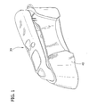
- FIG. 1 is a perspective view of a tympanic thermometer, in accordance with the principles of the present disclosure, mounted with a holder;
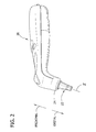
- FIG. 2 is a perspective view of the tympanic thermometer shown in FIG. 1;
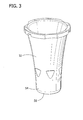
- FIG. 3 is a perspective view of a probe cover intended for mounting to the tympanic thermometer shown in FIG. 2;
- FIG. 4 is an exploded view, with parts separated, of a distal end of the tympanic thermometer shown in FIG. 2;
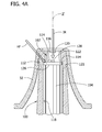
- FIG. 4A is a cross-sectional view of the probe cover mounted on the distal end of the tympanic thermometer shown in FIG. 2;
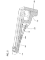
- FIG. 5 is an enlarged perspective cutaway view of the distal end of the tympanic thermometer shown in FIG. 2;
- FIG. 6 is a temperature gradient plot of a sensor can in one embodiment of the tympanic thermometer, in accordance with the present disclosure measured at 1.072 seconds after heat has been applied;
- FIG. 7 is a temperature gradient plot of the sensor can shown in FIG. 6 measured at 3.945 seconds after heat has been applied;
- FIG. 8 is a temperature gradient plot of the sensor can shown in FIG. 6 measured at 7.229 seconds after heat has been applied;
- FIG. 9 is a temperature gradient plot of the sensor can shown in FIG. 6 measured at 10 seconds after heat has been applied;
- FIG. 10 is a time versus temp graph of locations of the sensor temperatures of the sensor can for the time periods shown in FIG. 6-9;
- FIG. 11 is a temperature gradient plot for heat flux of a sensor can of the embodiment of the tympanic thermometer shown in FIG. 6 measured at 1.072 seconds after heat has been applied;
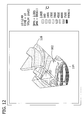
- FIG. 12 is a temperature gradient plot for heat flux of the sensor can shown in FIG. 6 measured at 10 seconds after heat has been applied;
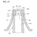
- FIG. 13 is a cross-sectional view of a sensor probe of another embodiment
- FIG. 14 is a fragmentary section of a sensor can of a tympanic thermometer of the prior art
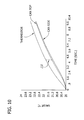
- FIG. 15 is a graph showing the time based temperature response of the sensor can of Fig. 14;
- FIG. 16 is a fragmentary section of a sensor can of a tympanic thermometer of the present invention.
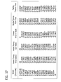
- FIG. 17 is a table showing temperature response of a sensor can in a tympanic thermometer of the present invention.
- FIG. 18 is a graph of the temperature versus time data of Fig. 17;
- FIG. 19 is a graph of temperature differentials across the sensor can.
- FIG. 20 is a cross-sectional view of a sensor probe of still another embodiment
- FIG. 21 is a perspective of a spring locator of the sensor probe of Fig. 20.
- FIG. 22 is a side elevation of the spring locator.
- thermometers for measuring body temperature
- a tympanic thermometer that includes a sensor having a nozzle disposed therewith that improves accuracy of temperature measurement.
- present disclosure finds application for the prevention, diagnosis and treatment of diseases, body ailments, etc. of a subject.
- principles relating to the tympanic thermometer disclosed include proper removal of a used probe cover via the ejection apparatus and indication to a practitioner whether a new, unused probe is mounted to the tympanic thermometer.
- proximal will refer to the portion of a structure that is closer to a practitioner, while the term “distal” will refer to the portion that is further from the practitioner.
- Figure 2 illustrates "proximal” and “distal” for the structure, which is the fully assembled and usable tympanic thermometer.
- subject refers to a human patient or other animal having its body temperature measured.
- prtitioner refers to a doctor, nurse, parent or other care provider utilizing a tympanic thermometer to measure a subject's body temperature, and may include support personnel.
- tympanic thermometer 20 includes the necessary electronics and/or processing components to perform temperature measurement via the tympanic membrane, as is known to one skilled in the art. It is further envisioned that tympanic thermometer 20 may include a waveguide to facilitate sensing of the tympanic membrane heat energy. However, in the illustrated embodiments, the waveguide is beneficially omitted.
- Tympanic thermometer 20 is releasably mounted in a holder 40 for storage in contemplation for use.
- Tympanic thermometer 20 and holder 40 may be fabricated from semi-rigid, rigid plastic and/or metal materials suitable for temperature measurement and related use. It is envisioned that holder 40 may include the electronics necessary to facilitate powering of tympanic thermometer 20, including, for example, battery charging capability, etc.
- tympanic thermometer 20 includes a cylindrical heat sensing probe, generally indicated at 22.
- Heat sensing probe 22 extends from an end 24 of tympanic thermometer 20 and defines a longitudinal axis X.
- Heat sensing probe 22 may have various geometric cross-sectional configurations, such as, for example, rectangular, elliptical, etc.
- heat sensing probe 22 includes a nozzle, generally indicated at 100, mounted on a base 106.
- the nozzle 100 includes a base 110 and an elongated nose portion 112 projecting distally from the base.
- the nozzle 100 may be fabricated from metal or other material which aides in the rapid exchange or transfer of heat.
- the nozzle 100 is formed of two parts (the base 110 and the nose portion 112) in the first illustrated embodiment. It will be understood that a nozzle can be formed as one piece or more than two pieces within the scope of the present invention. In particular, it is envisioned that the elongated nose section 112 can be formed of two or more pieces.
- the heat sensing probe 22 also includes a sensor can, generally indicated at 102, attached to temperature sensing electronics mounted on a distal end of a sensor housing 104 (or "retainer") received within the nozzle 100.
- the can 102 includes a sensor base 126 and a generally inverted cup-shaped tip 116 mounted on the base.
- An infrared sensor 122 e.g., a thermopile
- an infrared filter or window 120 and thermistor 124 are housed within the can 102.
- the sensor housing 104 is mounted on the base 106 of the probe 22 such that it extends generally coaxially within the nozzle 100.
- sensor housing 104 is fabricated from materials which provide for less thermo transmission (i.e., more insulated) than nozzle 100, for example, plastic or other similar matter. Stated another way, the material of the sensor housing 104 has a low thermal conductivity as compared to the thermal conductivity of the nozzle 100 and the base 126 of the can 102.
- thermal insulators may have a thermal conductivity (in units of W / mK or watts per meter degree Kelvin) of about 0.1 W / mK or less, while good thermal conductors may have a thermal conductivity of 100 W / mK or more.
- the base is preferably free of thermal connection to another metallic object besides the nozzle 100.
- a peripheral edge margin 114 of the base 126 of the can contacts an internal ridge 121 of the nozzle adjacent the nose portion 112 at the distal end. In this way, the base 126 of the can 102 is in thermal contact with the nozzle 100 at the nose portion 112 thereof.
- FIG. 4A when the can 102 and the sensor housing 104 are received in the nozzle 100, a peripheral edge margin 114 of the base 126 of the can contacts an internal ridge 121 of the nozzle adjacent the nose portion 112 at the distal end. In this way, the base 126 of the can 102 is in thermal contact with the nozzle 100 at the nose portion 112 thereof.
- FIG. 4A when the can 102 and the sensor housing 104 are received in the nozzle 100, a peripheral edge margin 114 of the base 126 of the can contacts an internal ridge 121 of the nozzle adjacent the nose portion 112 at the distal end. In this way, the base 126
- the remainder of the can 102 (i.e., any other portion of the can besides the base 126) does not contact any other structure.
- An air gap is formed between the proximal portion of the can 102 and the nose 112 of the nozzle 100.
- the base 126 of the can 102 is in thermal contact solely with the nozzle 100, as the sensor housing 104 is made of a thermally insulating material of low thermal conductivity.
- nozzle 100, sensor housing 104 and can 102 are fitted in a secure relationship. Such secure relationship may be established by way of adhesive, friction, press fitting and the like.
- An air gap 128 is also disposed between the nozzle 100 and sensor housing 104, providing additional thermal insulation against heat being drawn away from the base 126.
- a probe cover 32 is received on the nozzle 100 such that a distal portion of the cover is in thermal contact with the nose 112 of the nozzle.
- Probe cover 32 may be shaped, for example, frustoconically, or shaped in a tapered manner as to allow for easier insertion into the ear of the subject and attachment and detachment from the heat sensing probe 22.
- the probe cover 32 which is disposable, may be fabricated from materials suitable for measuring body temperature via the tympanic membrane with a tympanic thermometer measuring apparatus. These materials may include, for example, plastic materials, such as, for example, polypropylene, polyethylene, etc., depending on the particular temperature measurement application and/or preference of a practitioner.
- the probe cover 32 has a distal end 54 that is substantially enclosed by a film 56.
- Film 56 is substantially transparent to infrared radiation and configured to facilitate sensing of infrared emissions by heat sensing probe 22.
- the film 56 is advantageously impervious to ear wax, moisture and bacteria to prevent disease propagation.
- the film 56 has a thickness in the range of 0.0005 to 0.001 inches, although other ranges are contemplated.
- the film 56 may be semi-rigid or flexible, and can be monolithically formed with the remaining portion of the probe cover 32 or integrally connected thereto via, for example, thermal welding, etc.
- thermal welding etc.
- infrared energy IR (Fig. 4A) from the subject's tympanic membrane, for example, enters the can 102 through the window 120.
- This infrared energy may heat the can 102 and create a temperature gradient across the tip 116 from its distal end to its proximal end contacting the base 126. That is, the distal end can be much warmer than the proximal end.
- Heat from, for example, the ear of the subject is transferred from probe cover 32 to nozzle 100 to the base 126 of the can 102 via a path of heat flux HF (Fig. 4A).
- the path of heat flux HF heats the can 102 in order to reduce the temperature gradient across tip 116, thereby enabling a faster and more accurate temperature reading.
- the internal ridge 121 engages a distal side of the peripheral edge margin 114 of the base 126 to provide a heat conducting path from the nozzle 100 to the base (illustrated by arrow HF in Fig. 4A). It is contemplated herein that nozzle 100 may be both in physical contact with the peripheral edge margin 114 or in a close proximate relationship with peripheral edge margin 114 of can 102.
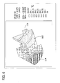
- heat transfer to the can 102 from peripheral edge margin 114 of the base 126 can occur at any local or single point of contact (FIGS. 6-9 and 11-12 disclose such point of contact along an upper portion of the peripheral edge margin 114) or along a plurality of contact points, for example, the entire portion of the peripheral edge margin 114.
- can 102 may have a plurality of lips, ribs or other similar structures, for example, detents, nubs, etc., which aide in the heat transfer from nozzle 100 to can 102 and ultimately to can tip 116.
- the peripheral edge margin 114 may also be formed in a variety of geometric configurations, e.g., helical, dashed, etc.
- can 102 may have a plurality of ridge members (not shown) made from a metal alloy or other material. Such ridge members may be made from separate materials, may be partially in contact with the body of can 102, or otherwise be adapted to reduce the temperature gradient from peripheral edge margin 114 to can tip 116.
- can 102 by way of or in addition to the formations of the peripheral edge margin 114, can be pre-heated electrically or by other means to certain preset temperatures. Ridge members assist in heat transfer from nozzle 100, such that the heat gradient from the peripheral edge margin 114 to can tip 116 is reduced. This reduction in the gradient across the sensor tip of can 102 provides for faster, more accurate results.
- sensor can 102 is situated at the distal end of the sensor housing 104 and at the distal end margin of the nozzle 100.
- Such relationship provides for the sensor to be included within or substantially close to the ear of a subject during a temperature reading.
- the waveguide of many conventional tympanic thermometers is not required.
- a thermal mass or heat sink to draw heat away from the sensor can 102 is not required.
- the prior art discloses sensor to ear relationships of this kind; however, these prior art relationships include unique differential heating issues of the sensor. As discussed below and shown in FIGS. 6-12, the differential heating problems of the prior art have been overcome.
- one embodiment of tympanic thermometer 20 includes heat sensing probe 22 at an initial temperature of 20 °C when a 40 °C temperature load is applied to the outside surface of probe cover 32. This is similar to taking heat sensing probe 22 from room temperature and disposing it within the ear of a human subject with a fever. As shown, radiation effects are applied to the top face of sensor housing 104 and nozzle 100. A transient analysis was run for ten (10) seconds for an aluminum nozzle design with a sensor contact.
- FIGS. 6-12 show temperature plots from a simulated temperature reading of the human ear. The data of such were confirmed from actual experimental tests performed on the ear of a subject.
- FIG. 6 shows a temperature plot of the temperature distribution across the sensor section of can 102 after 1.072 seconds. Areas of focus include the surface where the absorber chip and thermistor 124 (FIG. 4A) are located, the inside top of the sensor can and the inside side of the sensor can.
- FIG. 7 shows a temperature plot of the temperature distribution across the sensor-section after 3.945 seconds.
- FIG. 8 shows a temperature plot of the temperature distribution across the sensor section after 7.229 seconds.
- FIG. 9 shows a temperature plot of the temperature distribution across the sensor section after 10 seconds.
- FIG. 10 shows a plotted graph of the temperature distribution for the 10 second time transient.
- ( ⁇ T) is substantially constant across the 10 second time transient (that is, ( ⁇ T) essentially tracks the thermistor 124 (FIG. 4A)).
- Temperature readings can occur at substantially any time along the plotted graph of FIG. 10.
- FIG. 11 shows a temperature plot of the temperature gradient plot for heat flux after 1.072 seconds.
- FIG. 12 shows a temperature plot of the temperature gradient plot for heat flux after 10 seconds.
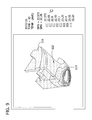
- a heat sensing probe is similar to the heat sensing probe 22 of the embodiment illustrated in FIGS. 1-5, therefore, corresponding components will have corresponding reference numbers.
- the difference between this probe and the prior embodiment is that this probe does not have a sensor housing.
- the sensor can 102 is preferably free of thermal connection to a thermally conductive structure other than the nozzle 100 that has a mass greater than the mass of the sensor can. Stated another way, the sensor can 102 is preferably free of thermal connection with any metallic object other than the nozzle 100. In fact in the version illustrated in Fig. 13, there is no structure secured to or in contact with a proximal side 126a of the base 126.
- the nozzle 100 instead defines an air space 130 on the proximal side of the base which acts as a thermal insulator so that heat conducted form the nozzle 100 to the base 126 is not drawn away from the base, but rather is conducted into the sensor can generally so that a thermal gradient between the base 126 (or proximal side of the sensor can 102) and the distal end of the sensor can opposite the base is minimized during the course of measuring temperature in the ear.
- air space means a space having no solid structure, but which may be filled with a gas of any kind, or be a vacuum.
- the base 126 of the can 102 is secured directly to the nozzle 100 without the need to mount the can on a separate structure, such as a sensor housing.
- the base 126 may be secured to the directly to the internal ridge 121 of the nozzle 100 using thermally conductive adhesive, such as an epoxy resin sold under the name Stycast® 2850 FT-FR and cured with Catalyst 9. (The trademark Stycast® is owned by National Starch and Chemical Company).
- the can 102 remains thermally insulated within the nozzle, except for the path of heat transfer, because air below the base 126 of the can within the nozzle 100 acts as an insulator.
- the base 126 of the can 102 can be secured within the nozzle 100 in other ways.
- a thermally insulated connector member may be secured directly to the nozzle 100, such as by a thread fastener, friction-fit, snap-fit or other connection, so that it contacts the proximal side of the base 126 of the can 102 and presses the distal side of the base in thermal contact with the internal ridge 121 of the nozzle.
- a flex circuit (alternatively, wires) from the can 102 run through the connector member and the nozzle 100 (not shown).
- the can 102 may also be directly secured to the nozzle 100, as described above with regard to the embodiment illustrated in FIG. 13.
- Other ways of securing the can 102 within the nozzle 100 so that the base 126 of the can is in thermal contact with the nozzle are within the scope of this invention.
- a computer model of temperature distribution over a sensor can C in a tympanic thermometer similar to conventional constructions is schematically illustrated.
- temperature nodes were located on a base B of the sensor can C near where the thermistor (not shown) would be located, on the side wall (SW) about half way up, and on the top wall (TW).
- the sensor can C was subjected to heat conditions approximating those experienced when the distal end of a tympanic thermometer probe is placed in a human ear.
- a heat sink (not shown) having a high thermal conductivity is in contact with a base B of the sensor can C to draw heat away from the can to avoid heating the can.
- the base B of the sensor can C remains relatively stable in temperature throughout the time the thermometer probe is received in the ear.
- a distal end (i.e., top wall TW) of the can C opposite the base B is heated by the influx of heat from the tympanic membrane and tissue adjacent to the end of the sensor can opposite the base.
- the distal end of the sensor can C already differs substantially from the temperature of the base (e.g., on the order of 1.5 degrees centigrade.
- the temperatures of the base B of the sensor can C, which corresponds to the temperature of the thermistor, and the temperature of the side wall SW of the can and the top wall TW of the can continue to diverge throughout the ten second interval of the model.
- This divergence in temperature makes the side wall SW and top wall TW of the sensor can C visible to the infrared sensor.
- the infrared sensor is measuring both the temperature differential of the tympanic membrane and the temperature differential of the side and top walls SW, TW.
- the infrared sensor operates by detecting differences in temperature from its own temperature of objects within its field of view.
- the thermistor temperature is an indication of the temperature of the infrared sensor.
- the infrared sensor sees the tympanic membrane which is indicative of the core body temperature. Readings from the sensor can side wall SW and top wall TW are not desirable and lead to error in the measurement. Temperature variations on the order of 1.5 degrees centigrade, as shown in the example illustrated in Figs. 14 and 15 cause significant error in the final temperature reading.
- Figures 16-19 show results of computer (finite element analysis) modeling for a tympanic thermometer constructed according to the principles of the present invention.
- the sensor can base 126 is in thermal contact with the nozzle 100 (not shown in Fig. 16) and thermally isolated from contact with another heat conductive material (such as a heat sink).
- Another heat conductive material such as a heat sink.
- Temperature nodes for monitoring temperature were placed in the same locations on sensor can 102 as for the sensor can C illustrated in Fig. 14.
- the sensor can 102 was subjected to heat conditions corresponding to those when the probe of the thermometer is placed inside the ear. A marked difference in temperature distribution from the example is readily apparent.
- the distal end (i.e., top wall 117) of the sensor can is heated, as before.
- the base 126 of the can 102 is also heated so that two heat fronts proceed from the base of the can and the top wall of the can to converge at a side wall 119 of the can.
- the difference in temperature between the thermistor and the sensor can top wall 117 and side wall 119 does not vary as greatly as before. Therefore, the can top wall 117 and side wall 119 are relatively invisible to the infrared sensor and produce less error in the temperature signal of the sensor.
- the temperatures of the base 126 are closely correlated and repeatedly cross over each other inasmuch as being the greater temperature during the approximately ten second interval of measurement.
- the can top wall 117 and side wall 119 are somewhat hotter than the base 126 (see Fig. 17).
- the base 126 is actually hotter than the can top and side walls 117, 119.
- the walls 117, 119 are again somewhat hotter.
- thermometer A graph of the difference in temperature between the base 126 (thermistor) and the sensor can top wall 117 and side wall 119 (respectively) is shown in Fig. 18.
- the temperature differences remain relatively small (on the order of about 0.5 degrees centigrade or less) throughout the period in which a temperature measurement would be taken. Accordingly, the sensor can walls 117, 119 provide only a very minimal error component to the temperature reading.
- the thermometer is able to operate more accurately over a wider range of ambient temperatures.
- a tympanic thermometer 220 of another embodiment is illustrated in Fig. 20.
- the parts of the tympanic thermometer 220 of Fig. 20 corresponding to the parts of the tympanic thermometers 20 of the prior figures will be indicated by the same reference numerals, plus "200".
- the tympanic thermometer 220 has a construction similar to the thermometer 20 shown in Figs. 1-4A, including having a nozzle 300, a sensor can 302 and a probe cover 232 received on the nozzle. However, instead of a sensor housing 104, a spring locator 303 and a spacer 305 made of a suitable thermally insulating material are used to engage and bias a base 326 of sensor can 302 against nozzle 300.
- the spring locator 303 comprises a cruciform platform 307 that engages the spacer 305 and pushes it against the underside of the base 326 of the sensor can 302.
- the cross shape of the platform 307 allows clearance for electrical leads 309 extending from the sensor.
- the platform 307 is connected to a mounting portion 311 of the spring locator 303 by two corrugated spring members 313.
- the mounting portion 311 is snapped into a pair of windows 315 in the nozzle 300 to lock the spring locator 303 in position in the nozzle.
- the spring members 313 are deflected from their relaxed positions when the mounting portion 311 is attached to the nozzle 300 so that they bias the spacer 305 to press the base 326 of the sensor can 302 against an annular internal ridge 321 of the nozzle thereby establishing thermal connection between the nozzle and the base.
- a reinforcing element 323 received inside the mounting portion 311 after it is secured to the nozzle 300 has a nose 325 that is received between the spring members 313 to increase the spring force of the spring members and to reinforce the spring members.
- the reinforcing member 323 is initially formed as one piece with the remainder of the spring locator 303 at the proximal end thereof.
- the reinforcing member 323 is attached by frangible connections 329 to the remainder of the spring locator 303 (see Fig. 22).
- the frangible connections 329 can be broken after the spring locator 303 is in place with tabs 331 of the mounting portion 311 received in the windows 315 of the nozzle 300 by pushing the mounting portion in a distal direction.
- the reinforcing member 323 is moved to the position shown in Fig. 20 with the nose 325 received between spring members 313 to hold the spring members in a balanced force position for maintaining an optimum spring force holding the can 302 and the spacer 305 against the nozzle 300.
Landscapes
- Physics & Mathematics (AREA)
- General Physics & Mathematics (AREA)
- Spectroscopy & Molecular Physics (AREA)
- Measuring And Recording Apparatus For Diagnosis (AREA)
Applications Claiming Priority (1)
| Application Number | Priority Date | Filing Date | Title |
|---|---|---|---|
| US11/419,424 US7434991B2 (en) | 2002-12-12 | 2006-05-19 | Thermal tympanic thermometer |
Publications (3)
| Publication Number | Publication Date |
|---|---|
| EP1857795A2 true EP1857795A2 (fr) | 2007-11-21 |
| EP1857795A3 EP1857795A3 (fr) | 2008-01-09 |
| EP1857795B1 EP1857795B1 (fr) | 2013-08-28 |
Family
ID=38266714
Family Applications (1)
| Application Number | Title | Priority Date | Filing Date |
|---|---|---|---|
| EP07009975.9A Active EP1857795B1 (fr) | 2006-05-19 | 2007-05-18 | Thermomètre auriculaire |
Country Status (7)
| Country | Link |
|---|---|
| US (1) | US7434991B2 (fr) |
| EP (1) | EP1857795B1 (fr) |
| CN (1) | CN101103907B (fr) |
| AU (1) | AU2007202236B2 (fr) |
| CA (1) | CA2589420C (fr) |
| MX (1) | MX2007006003A (fr) |
| TW (1) | TWI351941B (fr) |
Cited By (2)
| Publication number | Priority date | Publication date | Assignee | Title |
|---|---|---|---|---|
| EP3146301A4 (fr) * | 2014-05-19 | 2018-02-07 | CVG Management Corporation | Mesure de température à l'infrarouge et stabilisation de celle-ci |
| CN113196022A (zh) * | 2018-12-14 | 2021-07-30 | 生命回声株式会社 | 耳式体温计 |
Families Citing this family (25)
| Publication number | Priority date | Publication date | Assignee | Title |
|---|---|---|---|---|
| US20070100253A1 (en) * | 2005-11-03 | 2007-05-03 | Sherwood Services Ag | Electronic thermometer with sensor location |
| US7316507B2 (en) | 2005-11-03 | 2008-01-08 | Covidien Ag | Electronic thermometer with flex circuit location |
| US8308353B2 (en) * | 2007-03-26 | 2012-11-13 | Terumo Kabushiki Kaisha | Ear thermometer and method of manufacturing ear thermometer |
| US7749170B2 (en) | 2007-05-22 | 2010-07-06 | Tyco Healthcare Group Lp | Multiple configurable electronic thermometer |
| US8496377B2 (en) | 2007-12-31 | 2013-07-30 | Covidien Lp | Thermometer having molded probe component |
| US8186876B2 (en) * | 2009-04-20 | 2012-05-29 | Welch Allyn, Inc. | Calibrated assembly for IR thermometer apparatus |
| US8136985B2 (en) * | 2009-05-05 | 2012-03-20 | Welch Allyn, Inc. | IR thermometer thermal isolation tip assembly |
| US8226573B2 (en) * | 2009-11-16 | 2012-07-24 | Tyco Healthcare Group Lp | Thermometer probe |
| US8814792B2 (en) | 2010-07-27 | 2014-08-26 | Carefusion 303, Inc. | System and method for storing and forwarding data from a vital-signs monitor |
| US9585620B2 (en) | 2010-07-27 | 2017-03-07 | Carefusion 303, Inc. | Vital-signs patch having a flexible attachment to electrodes |
| US9615792B2 (en) | 2010-07-27 | 2017-04-11 | Carefusion 303, Inc. | System and method for conserving battery power in a patient monitoring system |
| US9357929B2 (en) * | 2010-07-27 | 2016-06-07 | Carefusion 303, Inc. | System and method for monitoring body temperature of a person |
| US9055925B2 (en) | 2010-07-27 | 2015-06-16 | Carefusion 303, Inc. | System and method for reducing false alarms associated with vital-signs monitoring |
| US9017255B2 (en) | 2010-07-27 | 2015-04-28 | Carefusion 303, Inc. | System and method for saving battery power in a patient monitoring system |
| US9420952B2 (en) | 2010-07-27 | 2016-08-23 | Carefusion 303, Inc. | Temperature probe suitable for axillary reading |
| USD675116S1 (en) * | 2011-09-01 | 2013-01-29 | Kaz Usa, Inc. | Thermometer cradle |
| USD675114S1 (en) * | 2011-09-01 | 2013-01-29 | Kaz Usa, Inc. | Thermometer cradle |
| USD675115S1 (en) * | 2011-09-01 | 2013-01-29 | Kaz Usa, Inc. | Thermometer cradle |
| US10054495B2 (en) | 2013-07-02 | 2018-08-21 | Exergen Corporation | Infrared contrasting color temperature measurement system |
| JP5827288B2 (ja) * | 2013-09-13 | 2015-12-02 | トヨタ自動車株式会社 | サーミスタモジュール |
| JP6221804B2 (ja) * | 2014-02-13 | 2017-11-01 | トヨタ自動車株式会社 | 回転電機のステータ |
| CN106236024A (zh) * | 2016-07-25 | 2016-12-21 | 深圳市菲明格科技有限公司 | 温度感应探头 |
| US11105683B2 (en) * | 2019-02-25 | 2021-08-31 | Hetaida Technology Co., Ltd. | Infrared thermometer capable of switching forehead temperature measurement mode and ear temperature measurement mode and switching method |
| CN115900963A (zh) * | 2021-09-28 | 2023-04-04 | 深圳迈瑞生物医疗电子股份有限公司 | 应用于耳温测量装置的护套及耳温测量设备 |
| TWI834375B (zh) * | 2022-11-08 | 2024-03-01 | 長庚學校財團法人長庚科技大學 | 數位式體溫計 |
Citations (3)
| Publication number | Priority date | Publication date | Assignee | Title |
|---|---|---|---|---|
| US5820264A (en) | 1996-03-25 | 1998-10-13 | Oriental System Technology, Inc. | Tympanic thermometer arrangement |
| US6179785B1 (en) | 1996-10-17 | 2001-01-30 | Sherwood Services, Ag | Ambient sensing feature for thermometer recalibration system |
| US6186959B1 (en) | 1997-06-03 | 2001-02-13 | Trutek, Inc. | Tympanic thermometer with modular sensing probe |
Family Cites Families (144)
| Publication number | Priority date | Publication date | Assignee | Title |
|---|---|---|---|---|
| US3491596A (en) * | 1967-10-02 | 1970-01-27 | Vito Charles P De | Temperature sensing device |
| US3738173A (en) * | 1971-11-22 | 1973-06-12 | Ivac Corp | Temperature sensing probe and disposable probe cover |
| US4005605A (en) * | 1974-07-22 | 1977-02-01 | Mikron Instrument Company, Inc. | Remote reading infrared thermometer |
| US4346427A (en) * | 1979-06-29 | 1982-08-24 | Robert Rothenhaus | Control device responsive to infrared radiation |
| GB2071316B (en) * | 1979-09-12 | 1983-11-09 | Raytek Inc | Hand-held digital temperature measuring instrument |
| US4343182A (en) * | 1980-07-14 | 1982-08-10 | Exergen Corporation | Radiation heat loss detector |
| US4456390A (en) * | 1981-10-26 | 1984-06-26 | Wahl Instruments, Inc. | Noncontact temperature measuring device |
| US4527896A (en) * | 1982-03-04 | 1985-07-09 | Mikron Instrument Company, Inc. | Infrared transducer-transmitter for non-contact temperature measurement |
| US4566808A (en) * | 1983-02-16 | 1986-01-28 | Exergen Corporation | Scanning radiation detector |
| JPS6054070A (ja) * | 1983-09-02 | 1985-03-28 | Nec Corp | 演算装置 |
| US4626686A (en) * | 1984-04-09 | 1986-12-02 | Exergen Corporation | Variable field of view heat scanner |
| US4790324A (en) * | 1984-10-23 | 1988-12-13 | Intelligent Medical Systems, Inc. | Method and apparatus for measuring internal body temperature utilizing infrared emissions |
| US5179936A (en) | 1984-10-23 | 1993-01-19 | Intelligent Medical Systems, Inc. | Disposable speculum with membrane bonding ring |
| US4602642A (en) * | 1984-10-23 | 1986-07-29 | Intelligent Medical Systems, Inc. | Method and apparatus for measuring internal body temperature utilizing infrared emissions |
| US4662360A (en) | 1984-10-23 | 1987-05-05 | Intelligent Medical Systems, Inc. | Disposable speculum |
| US4588306A (en) * | 1985-03-22 | 1986-05-13 | Chesebrough-Pond's Inc. | Electronic thermometer probe assembly |
| DE3650723T2 (de) * | 1985-04-17 | 2000-03-16 | Thermoscan Inc. | Elektronisches infrarot-thermometer und temperaturmessung |
| US4682898A (en) * | 1985-06-06 | 1987-07-28 | Honeywell Inc. | Method and apparatus for measuring a varying parameter |
| US4636091A (en) * | 1985-06-27 | 1987-01-13 | Exergen Corporation | Radiation detector having temperature readout |
| US4722612A (en) * | 1985-09-04 | 1988-02-02 | Wahl Instruments, Inc. | Infrared thermometers for minimizing errors associated with ambient temperature transients |
| US4784149A (en) * | 1986-01-13 | 1988-11-15 | Optical Sensors, Inc. | Infrared thermometer with automatic calibration |
| US4874253A (en) * | 1987-03-27 | 1989-10-17 | Exergen Corporation | Radiation detector with temperature display |
| US4854730A (en) * | 1987-08-13 | 1989-08-08 | Jacob Fraden | Radiation thermometer and method for measuring temperature |
| EP0411121A4 (en) * | 1987-12-25 | 1991-05-15 | Nippon Steel Corporation | Optical thermometer |
| US4896039A (en) * | 1987-12-31 | 1990-01-23 | Jacob Fraden | Active infrared motion detector and method for detecting movement |
| US4831258A (en) * | 1988-03-04 | 1989-05-16 | Exergen Corporation | Dual sensor radiation detector |
| JP2826337B2 (ja) * | 1988-04-12 | 1998-11-18 | シチズン時計株式会社 | 放射体温計 |
| US4867574A (en) * | 1988-05-19 | 1989-09-19 | Jenkofsky John J | Ultra high speed infrared temperature measuring device |
| US4895164A (en) * | 1988-09-15 | 1990-01-23 | Telatemp Corp. | Infrared clinical thermometer |
| US5018872A (en) * | 1988-11-01 | 1991-05-28 | Diatek, Inc. | Probe assembly for infrared thermometer |
| US4911559A (en) * | 1988-11-01 | 1990-03-27 | Diatek, Inc. | Disposable probe cover assembly for medical thermometer |
| US5445158A (en) | 1988-12-06 | 1995-08-29 | Exergen Corporation | Radiation detector probe |
| US5271407A (en) * | 1988-12-06 | 1993-12-21 | Exergen Corporation | Radiation detector suitable for tympanic temperature measurement |
| US5381796A (en) | 1992-05-22 | 1995-01-17 | Exergen Corporation | Ear thermometer radiation detector |
| US6219573B1 (en) * | 1989-04-14 | 2001-04-17 | Exergen Corporation | Radiation detector probe |
| US5325863A (en) | 1988-12-06 | 1994-07-05 | Exergen Corporation | Radiation detector with high thermal stability |
| US5199436A (en) * | 1988-12-06 | 1993-04-06 | Exergen Corporation | Radiation detector having improved accuracy |
| US5012813A (en) * | 1988-12-06 | 1991-05-07 | Exergen Corporation | Radiation detector having improved accuracy |
| US4993419A (en) * | 1988-12-06 | 1991-02-19 | Exergen Corporation | Radiation detector suitable for tympanic temperature measurement |
| US4900162A (en) * | 1989-03-20 | 1990-02-13 | Ivac Corporation | Infrared thermometry system and method |
| US5019804A (en) * | 1989-04-10 | 1991-05-28 | Jacob Fraden | Apparatus and method for detecting movement of an object |
| US5017019A (en) * | 1989-04-14 | 1991-05-21 | Exergen Corporation | Radiation detector for differential biological temperature readings |
| US5163418A (en) * | 1989-09-19 | 1992-11-17 | Thermoscan Inc. | Speculum cover |
| US5054936A (en) * | 1989-11-16 | 1991-10-08 | Jacob Fraden | Sensor for active thermal detection |
| US4993424A (en) * | 1989-12-04 | 1991-02-19 | Diatek, Incorporated | Infrared medical thermometer |
| EP0445783B1 (fr) | 1990-03-08 | 1996-02-07 | Ivac Corporation | Sonde thermiquement isolée |
| US5066142A (en) * | 1990-03-08 | 1991-11-19 | Ivac Corporation | Protective apparatus for a biomedical probe |
| US5150969A (en) * | 1990-03-12 | 1992-09-29 | Ivac Corporation | System and method for temperature determination and calibration in a biomedical probe |
| US5081359A (en) * | 1990-05-23 | 1992-01-14 | Exergen Corporation | Differential thermal sensor |
| DE69114502T3 (de) * | 1990-08-01 | 2002-10-02 | Exergen Corp., Newton | Strahlungsdetektor mit entferntem temperaturreferenzort |
| US5229612B1 (en) * | 1990-08-01 | 1998-04-14 | Exergen Corp | Radiation detector with remote temperature reference |
| US5159936A (en) * | 1990-08-17 | 1992-11-03 | Mark Yelderman | Noncontact infrared tympanic thermometer |
| US5088834A (en) * | 1990-08-24 | 1992-02-18 | Thermoscan Inc. | Unitary probe cover |
| US5119436A (en) * | 1990-09-24 | 1992-06-02 | Kulicke And Soffa Industries, Inc | Method of centering bond positions |
| CA2098313C (fr) * | 1990-12-12 | 2001-06-19 | Covidien Ag | Thermometre a infrarouges utilisant une cartographie etalonnee |
| JP3179788B2 (ja) * | 1991-01-17 | 2001-06-25 | 三菱電機株式会社 | 半導体記憶装置 |
| US5469855A (en) | 1991-03-08 | 1995-11-28 | Exergen Corporation | Continuous temperature monitor |
| US5178464A (en) * | 1991-04-19 | 1993-01-12 | Thermoscan Inc. | Balance infrared thermometer and method for measuring temperature |
| US5127742A (en) * | 1991-04-19 | 1992-07-07 | Thermoscan Inc. | Apparatus and method for temperature measurement by radiation |
| US5183337A (en) * | 1991-07-08 | 1993-02-02 | Exergen Corporation | Thermometer calibration |
| US5333784A (en) | 1993-03-02 | 1994-08-02 | Exergen Corporation | Radiation detector with thermocouple calibration and remote temperature reference |
| US5368038A (en) | 1993-03-08 | 1994-11-29 | Thermoscan Inc. | Optical system for an infrared thermometer |
| US5411032A (en) | 1993-06-18 | 1995-05-02 | Infra-Temp Inc. | Electronic thermometer probe cover |
| DE4331574C2 (de) | 1993-09-16 | 1997-07-10 | Heimann Optoelectronics Gmbh | Infrarot-Sensormodul |
| US20030185273A1 (en) | 1993-09-17 | 2003-10-02 | Hollander Milton Bernard | Laser directed temperature measurement |
| US5645349A (en) | 1994-01-10 | 1997-07-08 | Thermoscan Inc. | Noncontact active temperature sensor |
| WO1995022928A1 (fr) | 1994-02-28 | 1995-08-31 | Economation, Inc. | Thermometre tympanique a infrarouges |
| US5626139A (en) | 1994-09-23 | 1997-05-06 | Artech Industries, Inc. | Tympanic thermometer |
| DE19543096C2 (de) | 1995-11-18 | 1998-07-23 | Braun Ag | Infrarot-Strahlungsthermometer |
| CN100514012C (zh) | 1995-11-18 | 2009-07-15 | 布劳恩股份有限公司 | 确定红外温度计的信号值的方法及红外温度计 |
| KR100279338B1 (ko) | 1995-12-28 | 2001-03-02 | 타테이시 요시오 | 적외선온도계 |
| US5645350A (en) | 1996-04-12 | 1997-07-08 | Jang; Chen-Chang | Hygienic protecting device for an electronic thermometer |
| US5874736A (en) | 1996-10-25 | 1999-02-23 | Exergen Corporation | Axillary infrared thermometer and method of use |
| FR2773214B1 (fr) | 1996-12-11 | 2002-05-31 | Omega Engineering | Procede et dispositif pour la mesure par infrarouge de la temperature d'une surface |
| EP1304555B1 (fr) | 1997-07-16 | 2007-05-23 | Terumo Kabushiki Kaisha | Thermomètre tympanique |
| JP4018782B2 (ja) | 1997-09-10 | 2007-12-05 | シチズンホールディングス株式会社 | 放射温度計 |
| DE19757447A1 (de) | 1997-12-23 | 1999-07-01 | Braun Gmbh | Temperaturberechnungsverfahren für Strahlungsthermometer |
| US6129673A (en) | 1998-06-08 | 2000-10-10 | Advanced Monitors, Corp. | Infrared thermometer |
| US6224256B1 (en) | 1998-06-18 | 2001-05-01 | Harry Bala | Cover for medical probe |
| US6292685B1 (en) * | 1998-09-11 | 2001-09-18 | Exergen Corporation | Temporal artery temperature detector |
| IL126224A0 (en) | 1998-09-15 | 1999-05-09 | Gerlitz Jonathan | Ear thermometer and detector therefor |
| CN1147717C (zh) | 1998-09-16 | 2004-04-28 | 布劳恩有限公司 | 测定温度的方法和具有多个红外传感器元件的辐射温度计 |
| JP3514138B2 (ja) | 1998-09-29 | 2004-03-31 | テルモ株式会社 | プローブカバー取り外し機構および耳式体温計 |
| DE69934508T2 (de) | 1998-10-20 | 2007-09-27 | Omron Healthcare Co., Ltd. | Infrarotthermometer |
| DE29819056U1 (de) | 1998-10-26 | 1999-02-25 | Chen, Chao-Wang, Taipeh/T'ai-pei | Infrarotthermometer |
| CN1185983C (zh) | 1998-12-15 | 2005-01-26 | 西铁城钟表股份有限公司 | 辐射温度计 |
| DE29902276U1 (de) | 1999-02-09 | 1999-04-15 | Chen, Chao-Wang, Taipeh/T'ai-pei | Infrarotmeßfühler für ein Thermometer |
| US6139182A (en) | 1999-03-01 | 2000-10-31 | Thermoscan, Inc | Enhanced protective cover for use in an IR thermometer |
| DE19913672A1 (de) | 1999-03-25 | 2000-11-02 | Braun Gmbh | Infrarot-Thermometer mit einer beheizbaren Meßspitze und Schutzkappe |
| DE29907098U1 (de) | 1999-04-21 | 1999-07-22 | Chen, Chao-Wang, Taipeh/T'ai-pei | Prüfkopf für ein Infrarot-Thermometer |
| US6901089B1 (en) | 1999-07-02 | 2005-05-31 | Milton Bernard Hollander | Laser instrument |
| DE19942214A1 (de) | 1999-09-03 | 2001-03-08 | Braun Gmbh | Beheizbarer Infrarot-Sensor und Infrarot-Thermometer mit einem derartigen Sensor |
| USD464555S1 (en) | 1999-10-28 | 2002-10-22 | The Eastern Company | Portions of a clamp bracket assembly for use with push button latch and lock operating assemblies |
| US6983753B1 (en) | 1999-11-17 | 2006-01-10 | Smithkline Beecham Corporation | Infrared thermography |
| US6319206B1 (en) | 1999-11-24 | 2001-11-20 | Exergen Corporation | Temporal thermometer disposable cap |
| GB0005926D0 (en) | 2000-03-10 | 2000-05-03 | Univ Glasgow | Microwave radiometry |
| US6390671B1 (en) | 2000-04-28 | 2002-05-21 | K-Jump Health Co., Ltd. | Probe cover with film insert |
| IT1317648B1 (it) | 2000-05-19 | 2003-07-15 | Tecnica S R L | Termometro ad infrarossi perfezionato |
| DE10025157A1 (de) * | 2000-05-23 | 2001-11-29 | Braun Gmbh | Infrarot-Strahlungsthermometer mit veränderbarer Meßspitze |
| JP3690387B2 (ja) | 2000-06-13 | 2005-08-31 | オムロンヘルスケア株式会社 | 放射温度計 |
| TW437956U (en) | 2000-09-15 | 2001-05-28 | Peng Shau Yu | Ear thermometer with rotating-type probing head |
| EP1239271A1 (fr) | 2001-03-07 | 2002-09-11 | Microlife Intellectual Property GmbH | Thermomètre médical à infrarouge |
| EP1249691A1 (fr) | 2001-04-11 | 2002-10-16 | Omron Corporation | Thermomètre médical électronique |
| KR100363284B1 (ko) | 2001-05-22 | 2002-12-11 | 주식회사 메타텍 | 적외선 체온계 |
| JP2002345761A (ja) | 2001-05-22 | 2002-12-03 | Omron Corp | 赤外線体温計用プローブ |
| JP3945189B2 (ja) | 2001-06-01 | 2007-07-18 | オムロンヘルスケア株式会社 | 赤外線体温計 |
| JP3900865B2 (ja) | 2001-06-04 | 2007-04-04 | オムロンヘルスケア株式会社 | 赤外線体温計,赤外線体温計の温度状態推定方法,情報報知方法及び測定動作管理方法 |
| US6637931B2 (en) | 2001-07-19 | 2003-10-28 | Oriental System Technology Inc. | Probe for use in an infrared thermometer |
| US20030067958A1 (en) | 2001-10-09 | 2003-04-10 | Chen-Chang Jang | Infrared thermometer as measured on forehead artery area |
| US6749334B2 (en) * | 2002-08-09 | 2004-06-15 | Radiant Innovation Inc. | Ear thermometer probe structure |
| US20040047392A1 (en) | 2002-09-06 | 2004-03-11 | Shu-Mei Wu | Apparatus for measuring ear and forehead temperature |
| US6979121B2 (en) | 2002-10-18 | 2005-12-27 | Mesure Technology, Co., Ltd. | Temperature probe and thermometer having the same |
| US6970491B2 (en) | 2002-10-30 | 2005-11-29 | Photodigm, Inc. | Planar and wafer level packaging of semiconductor lasers and photo detectors for transmitter optical sub-assemblies |
| TW567054B (en) | 2002-11-28 | 2003-12-21 | Actherm Inc | Method for assembling electric clinical thermometer and structure thereof |
| US6981796B2 (en) | 2002-12-04 | 2006-01-03 | Actherm Inc. | Electronic thermometer |
| JP2004191075A (ja) | 2002-12-06 | 2004-07-08 | Matsushita Electric Ind Co Ltd | 温度測定装置、温度補正方法、及び画像形成装置 |
| US7108419B2 (en) * | 2002-12-12 | 2006-09-19 | Sherwood Services Ag | Thermal tympanic thermometer tip |
| US6950028B2 (en) | 2003-04-25 | 2005-09-27 | Stephen Eliot Zweig | Electronic time-temperature indicator |
| US6886979B2 (en) | 2003-05-23 | 2005-05-03 | Carl J Conforti | Temperature measure device |
| US7374336B2 (en) | 2003-06-16 | 2008-05-20 | Jacob Fraden | Contact thermometer for body cavity |
| TWM266444U (en) | 2003-08-29 | 2005-06-01 | Mesure Technology Co Ltd | Foldable sensing head and its clinical thermometer |
| DE10341433A1 (de) | 2003-09-09 | 2005-03-31 | Braun Gmbh | Beheizbarer Infrarot-Sensor und Infrarot-Thermometer mit einem derartigen Infrarot-Sensor |
| US20050083991A1 (en) | 2003-10-17 | 2005-04-21 | Anthony Wong | Probe cover storage system for ear thermometer |
| US20050085733A1 (en) | 2003-10-17 | 2005-04-21 | Anthony Wong | Ear thermometer illumination system |
| US7021824B2 (en) | 2003-10-20 | 2006-04-04 | Welch Allyn, Inc. | Switch assembly for thermometry apparatus |
| TWM244878U (en) | 2003-10-21 | 2004-10-01 | Innovatech Inc | Electric ear thermometer capable of storing a number of people's data |
| TW593993B (en) | 2003-11-03 | 2004-06-21 | Oriental System Technology Inc | Electrical thermometer |
| EP1530034A1 (fr) | 2003-11-05 | 2005-05-11 | Microlife Intellectual Property GmbH | Thermomètre infrarouge et un procédé pour la déterminer la température |
| US20050157775A1 (en) | 2003-11-17 | 2005-07-21 | Maverick Industries, Inc. | Temperature probe and use thereof |
| US7611278B2 (en) | 2003-12-02 | 2009-11-03 | White Box, Inc. | Infrared thermometers |
| US20050207470A1 (en) | 2004-01-26 | 2005-09-22 | Bennett Timothy J | Focusing thermometer |
| TWM251738U (en) | 2004-01-30 | 2004-12-01 | Yuan Ho Harmony Co Ltd | Infrared temperature sensor |
| WO2005092177A1 (fr) | 2004-03-22 | 2005-10-06 | Bodymedia, Inc. | Dispositif non invasif de surveillance de la temperature |
| US20050209516A1 (en) | 2004-03-22 | 2005-09-22 | Jacob Fraden | Vital signs probe |
| US20050226307A1 (en) | 2004-04-07 | 2005-10-13 | Sherin Lussier | Infrared thermometer |
| US20050276308A1 (en) | 2004-06-10 | 2005-12-15 | Pint Charles S | Method and apparatus for measuring temperature and emissivity |
| US20060050769A1 (en) * | 2004-09-08 | 2006-03-09 | Yung-Ku Lee | Waterproof infrared ear thermometer |
| TW200615520A (en) * | 2004-11-09 | 2006-05-16 | Norm Pacific Automat Corp | Infrared thermometer |
| JP2005128034A (ja) | 2004-12-27 | 2005-05-19 | Omron Healthcare Co Ltd | 放射温度計 |
| JP2005128031A (ja) | 2004-12-27 | 2005-05-19 | Omron Healthcare Co Ltd | 放射温度計 |
| JP4148219B2 (ja) | 2004-12-27 | 2008-09-10 | オムロンヘルスケア株式会社 | 放射温度計 |
| JP2005128033A (ja) | 2004-12-27 | 2005-05-19 | Omron Healthcare Co Ltd | 放射温度計 |
| US20060153278A1 (en) * | 2005-01-11 | 2006-07-13 | Kun-Sung Chen | Ear thermometer |
| US20060198424A1 (en) * | 2005-03-02 | 2006-09-07 | Kun-Sung Chen | Probe structure for an ear thermometer |
-
2006
- 2006-05-19 US US11/419,424 patent/US7434991B2/en not_active Expired - Lifetime
-
2007
- 2007-05-17 CA CA2589420A patent/CA2589420C/fr active Active
- 2007-05-18 EP EP07009975.9A patent/EP1857795B1/fr active Active
- 2007-05-18 MX MX2007006003A patent/MX2007006003A/es active IP Right Grant
- 2007-05-18 TW TW096117847A patent/TWI351941B/zh not_active IP Right Cessation
- 2007-05-18 AU AU2007202236A patent/AU2007202236B2/en active Active
- 2007-05-21 CN CN2007101388118A patent/CN101103907B/zh not_active Expired - Fee Related
Patent Citations (3)
| Publication number | Priority date | Publication date | Assignee | Title |
|---|---|---|---|---|
| US5820264A (en) | 1996-03-25 | 1998-10-13 | Oriental System Technology, Inc. | Tympanic thermometer arrangement |
| US6179785B1 (en) | 1996-10-17 | 2001-01-30 | Sherwood Services, Ag | Ambient sensing feature for thermometer recalibration system |
| US6186959B1 (en) | 1997-06-03 | 2001-02-13 | Trutek, Inc. | Tympanic thermometer with modular sensing probe |
Cited By (4)
| Publication number | Priority date | Publication date | Assignee | Title |
|---|---|---|---|---|
| US10260954B2 (en) | 2010-07-08 | 2019-04-16 | Cvg Management Corporation | Infrared temperature measurement and stabilization thereof |
| EP3146301A4 (fr) * | 2014-05-19 | 2018-02-07 | CVG Management Corporation | Mesure de température à l'infrarouge et stabilisation de celle-ci |
| CN113196022A (zh) * | 2018-12-14 | 2021-07-30 | 生命回声株式会社 | 耳式体温计 |
| EP3896413A4 (fr) * | 2018-12-14 | 2022-09-07 | Bio Echo Net Inc. | Thermomètre auriculaire |
Also Published As
| Publication number | Publication date |
|---|---|
| CN101103907A (zh) | 2008-01-16 |
| US7434991B2 (en) | 2008-10-14 |
| TW200800099A (en) | 2008-01-01 |
| EP1857795B1 (fr) | 2013-08-28 |
| CA2589420A1 (fr) | 2007-11-19 |
| AU2007202236A1 (en) | 2007-12-06 |
| AU2007202236B2 (en) | 2009-08-20 |
| MX2007006003A (es) | 2008-12-08 |
| US20060239332A1 (en) | 2006-10-26 |
| CN101103907B (zh) | 2010-11-03 |
| TWI351941B (en) | 2011-11-11 |
| CA2589420C (fr) | 2012-07-17 |
| EP1857795A3 (fr) | 2008-01-09 |
Similar Documents
| Publication | Publication Date | Title |
|---|---|---|
| US7841767B2 (en) | Thermal tympanic thermometer | |
| EP1857795B1 (fr) | Thermomètre auriculaire | |
| EP0411121A1 (fr) | Thermometre optique | |
| JPH0528617B2 (fr) | ||
| CN100535619C (zh) | 耳式医用温度计 | |
| JP2004526147A (ja) | 温度測定装置 | |
| KR20010069959A (ko) | 적외선 체온계 | |
| KR200243898Y1 (ko) | 적외선 체온계 | |
| AU2007200873B2 (en) | Thermal tympanic thermometer tip | |
| HK1074076B (en) | Thermal tympanic thermometer tip | |
| CN216283957U (zh) | 一种耳式体温计及温度测量装置的探头 | |
| JP2000139853A (ja) | 鼓膜温度計 |
Legal Events
| Date | Code | Title | Description |
|---|---|---|---|
| PUAI | Public reference made under article 153(3) epc to a published international application that has entered the european phase |
Free format text: ORIGINAL CODE: 0009012 |
|
| 17P | Request for examination filed |
Effective date: 20070518 |
|
| AK | Designated contracting states |
Kind code of ref document: A2 Designated state(s): AT BE BG CH CY CZ DE DK EE ES FI FR GB GR HU IE IS IT LI LT LU LV MC MT NL PL PT RO SE SI SK TR |
|
| AX | Request for extension of the european patent |
Extension state: AL BA HR MK YU |
|
| PUAL | Search report despatched |
Free format text: ORIGINAL CODE: 0009013 |
|
| AK | Designated contracting states |
Kind code of ref document: A3 Designated state(s): AT BE BG CH CY CZ DE DK EE ES FI FR GB GR HU IE IS IT LI LT LU LV MC MT NL PL PT RO SE SI SK TR |
|
| AX | Request for extension of the european patent |
Extension state: AL BA HR MK YU |
|
| 17Q | First examination report despatched |
Effective date: 20080306 |
|
| AKX | Designation fees paid |
Designated state(s): AT BE BG CH CY CZ DE DK EE ES FI FR GB GR HU IE IS IT LI LT LU LV MC MT NL PL PT RO SE SI SK TR |
|
| GRAP | Despatch of communication of intention to grant a patent |
Free format text: ORIGINAL CODE: EPIDOSNIGR1 |
|
| REG | Reference to a national code |
Ref country code: DE Ref legal event code: R079 Ref document number: 602007032497 Country of ref document: DE Free format text: PREVIOUS MAIN CLASS: G01J0005040000 Ipc: G01J0005020000 |
|
| RIC1 | Information provided on ipc code assigned before grant |
Ipc: G01J 5/06 20060101ALI20130320BHEP Ipc: G01J 5/02 20060101AFI20130320BHEP Ipc: G01J 5/12 20060101ALI20130320BHEP |
|
| GRAS | Grant fee paid |
Free format text: ORIGINAL CODE: EPIDOSNIGR3 |
|
| GRAP | Despatch of communication of intention to grant a patent |
Free format text: ORIGINAL CODE: EPIDOSNIGR1 |
|
| INTG | Intention to grant announced |
Effective date: 20130514 |
|
| GRAA | (expected) grant |
Free format text: ORIGINAL CODE: 0009210 |
|
| AK | Designated contracting states |
Kind code of ref document: B1 Designated state(s): AT BE BG CH CY CZ DE DK EE ES FI FR GB GR HU IE IS IT LI LT LU LV MC MT NL PL PT RO SE SI SK TR |
|
| RAP1 | Party data changed (applicant data changed or rights of an application transferred) |
Owner name: COVIDIEN AG |
|
| REG | Reference to a national code |
Ref country code: GB Ref legal event code: FG4D |
|
| REG | Reference to a national code |
Ref country code: CH Ref legal event code: EP |
|
| REG | Reference to a national code |
Ref country code: AT Ref legal event code: REF Ref document number: 629609 Country of ref document: AT Kind code of ref document: T Effective date: 20130915 |
|
| REG | Reference to a national code |
Ref country code: IE Ref legal event code: FG4D |
|
| REG | Reference to a national code |
Ref country code: NL Ref legal event code: T3 |
|
| REG | Reference to a national code |
Ref country code: DE Ref legal event code: R096 Ref document number: 602007032497 Country of ref document: DE Effective date: 20131024 |
|
| REG | Reference to a national code |
Ref country code: AT Ref legal event code: MK05 Ref document number: 629609 Country of ref document: AT Kind code of ref document: T Effective date: 20130828 |
|
| REG | Reference to a national code |
Ref country code: LT Ref legal event code: MG4D |
|
| PG25 | Lapsed in a contracting state [announced via postgrant information from national office to epo] |
Ref country code: IS Free format text: LAPSE BECAUSE OF FAILURE TO SUBMIT A TRANSLATION OF THE DESCRIPTION OR TO PAY THE FEE WITHIN THE PRESCRIBED TIME-LIMIT Effective date: 20131228 Ref country code: PT Free format text: LAPSE BECAUSE OF FAILURE TO SUBMIT A TRANSLATION OF THE DESCRIPTION OR TO PAY THE FEE WITHIN THE PRESCRIBED TIME-LIMIT Effective date: 20131230 Ref country code: AT Free format text: LAPSE BECAUSE OF FAILURE TO SUBMIT A TRANSLATION OF THE DESCRIPTION OR TO PAY THE FEE WITHIN THE PRESCRIBED TIME-LIMIT Effective date: 20130828 Ref country code: SE Free format text: LAPSE BECAUSE OF FAILURE TO SUBMIT A TRANSLATION OF THE DESCRIPTION OR TO PAY THE FEE WITHIN THE PRESCRIBED TIME-LIMIT Effective date: 20130828 Ref country code: LT Free format text: LAPSE BECAUSE OF FAILURE TO SUBMIT A TRANSLATION OF THE DESCRIPTION OR TO PAY THE FEE WITHIN THE PRESCRIBED TIME-LIMIT Effective date: 20130828 Ref country code: CY Free format text: LAPSE BECAUSE OF FAILURE TO SUBMIT A TRANSLATION OF THE DESCRIPTION OR TO PAY THE FEE WITHIN THE PRESCRIBED TIME-LIMIT Effective date: 20130703 |
|
| PG25 | Lapsed in a contracting state [announced via postgrant information from national office to epo] |
Ref country code: PL Free format text: LAPSE BECAUSE OF FAILURE TO SUBMIT A TRANSLATION OF THE DESCRIPTION OR TO PAY THE FEE WITHIN THE PRESCRIBED TIME-LIMIT Effective date: 20130828 Ref country code: SI Free format text: LAPSE BECAUSE OF FAILURE TO SUBMIT A TRANSLATION OF THE DESCRIPTION OR TO PAY THE FEE WITHIN THE PRESCRIBED TIME-LIMIT Effective date: 20130828 Ref country code: ES Free format text: LAPSE BECAUSE OF FAILURE TO SUBMIT A TRANSLATION OF THE DESCRIPTION OR TO PAY THE FEE WITHIN THE PRESCRIBED TIME-LIMIT Effective date: 20130828 Ref country code: BE Free format text: LAPSE BECAUSE OF FAILURE TO SUBMIT A TRANSLATION OF THE DESCRIPTION OR TO PAY THE FEE WITHIN THE PRESCRIBED TIME-LIMIT Effective date: 20130828 Ref country code: GR Free format text: LAPSE BECAUSE OF FAILURE TO SUBMIT A TRANSLATION OF THE DESCRIPTION OR TO PAY THE FEE WITHIN THE PRESCRIBED TIME-LIMIT Effective date: 20131129 Ref country code: LV Free format text: LAPSE BECAUSE OF FAILURE TO SUBMIT A TRANSLATION OF THE DESCRIPTION OR TO PAY THE FEE WITHIN THE PRESCRIBED TIME-LIMIT Effective date: 20130828 Ref country code: FI Free format text: LAPSE BECAUSE OF FAILURE TO SUBMIT A TRANSLATION OF THE DESCRIPTION OR TO PAY THE FEE WITHIN THE PRESCRIBED TIME-LIMIT Effective date: 20130828 |
|
| PG25 | Lapsed in a contracting state [announced via postgrant information from national office to epo] |
Ref country code: CY Free format text: LAPSE BECAUSE OF FAILURE TO SUBMIT A TRANSLATION OF THE DESCRIPTION OR TO PAY THE FEE WITHIN THE PRESCRIBED TIME-LIMIT Effective date: 20130828 |
|
| PG25 | Lapsed in a contracting state [announced via postgrant information from national office to epo] |
Ref country code: DK Free format text: LAPSE BECAUSE OF FAILURE TO SUBMIT A TRANSLATION OF THE DESCRIPTION OR TO PAY THE FEE WITHIN THE PRESCRIBED TIME-LIMIT Effective date: 20130828 Ref country code: SK Free format text: LAPSE BECAUSE OF FAILURE TO SUBMIT A TRANSLATION OF THE DESCRIPTION OR TO PAY THE FEE WITHIN THE PRESCRIBED TIME-LIMIT Effective date: 20130828 Ref country code: CZ Free format text: LAPSE BECAUSE OF FAILURE TO SUBMIT A TRANSLATION OF THE DESCRIPTION OR TO PAY THE FEE WITHIN THE PRESCRIBED TIME-LIMIT Effective date: 20130828 Ref country code: EE Free format text: LAPSE BECAUSE OF FAILURE TO SUBMIT A TRANSLATION OF THE DESCRIPTION OR TO PAY THE FEE WITHIN THE PRESCRIBED TIME-LIMIT Effective date: 20130828 Ref country code: RO Free format text: LAPSE BECAUSE OF FAILURE TO SUBMIT A TRANSLATION OF THE DESCRIPTION OR TO PAY THE FEE WITHIN THE PRESCRIBED TIME-LIMIT Effective date: 20130828 |
|
| PG25 | Lapsed in a contracting state [announced via postgrant information from national office to epo] |
Ref country code: IT Free format text: LAPSE BECAUSE OF FAILURE TO SUBMIT A TRANSLATION OF THE DESCRIPTION OR TO PAY THE FEE WITHIN THE PRESCRIBED TIME-LIMIT Effective date: 20130828 |
|
| REG | Reference to a national code |
Ref country code: DE Ref legal event code: R097 Ref document number: 602007032497 Country of ref document: DE |
|
| PLBE | No opposition filed within time limit |
Free format text: ORIGINAL CODE: 0009261 |
|
| STAA | Information on the status of an ep patent application or granted ep patent |
Free format text: STATUS: NO OPPOSITION FILED WITHIN TIME LIMIT |
|
| 26N | No opposition filed |
Effective date: 20140530 |
|
| REG | Reference to a national code |
Ref country code: DE Ref legal event code: R097 Ref document number: 602007032497 Country of ref document: DE Effective date: 20140530 |
|
| PG25 | Lapsed in a contracting state [announced via postgrant information from national office to epo] |
Ref country code: LU Free format text: LAPSE BECAUSE OF FAILURE TO SUBMIT A TRANSLATION OF THE DESCRIPTION OR TO PAY THE FEE WITHIN THE PRESCRIBED TIME-LIMIT Effective date: 20140518 |
|
| REG | Reference to a national code |
Ref country code: CH Ref legal event code: PL |
|
| PG25 | Lapsed in a contracting state [announced via postgrant information from national office to epo] |
Ref country code: MC Free format text: LAPSE BECAUSE OF FAILURE TO SUBMIT A TRANSLATION OF THE DESCRIPTION OR TO PAY THE FEE WITHIN THE PRESCRIBED TIME-LIMIT Effective date: 20130828 Ref country code: CH Free format text: LAPSE BECAUSE OF NON-PAYMENT OF DUE FEES Effective date: 20140531 Ref country code: LI Free format text: LAPSE BECAUSE OF NON-PAYMENT OF DUE FEES Effective date: 20140531 |
|
| PG25 | Lapsed in a contracting state [announced via postgrant information from national office to epo] |
Ref country code: MT Free format text: LAPSE BECAUSE OF FAILURE TO SUBMIT A TRANSLATION OF THE DESCRIPTION OR TO PAY THE FEE WITHIN THE PRESCRIBED TIME-LIMIT Effective date: 20130828 |
|
| REG | Reference to a national code |
Ref country code: FR Ref legal event code: PLFP Year of fee payment: 10 |
|
| PG25 | Lapsed in a contracting state [announced via postgrant information from national office to epo] |
Ref country code: BG Free format text: LAPSE BECAUSE OF FAILURE TO SUBMIT A TRANSLATION OF THE DESCRIPTION OR TO PAY THE FEE WITHIN THE PRESCRIBED TIME-LIMIT Effective date: 20130828 |
|
| PGFP | Annual fee paid to national office [announced via postgrant information from national office to epo] |
Ref country code: NL Payment date: 20160422 Year of fee payment: 10 |
|
| PG25 | Lapsed in a contracting state [announced via postgrant information from national office to epo] |
Ref country code: HU Free format text: LAPSE BECAUSE OF FAILURE TO SUBMIT A TRANSLATION OF THE DESCRIPTION OR TO PAY THE FEE WITHIN THE PRESCRIBED TIME-LIMIT; INVALID AB INITIO Effective date: 20070518 Ref country code: TR Free format text: LAPSE BECAUSE OF FAILURE TO SUBMIT A TRANSLATION OF THE DESCRIPTION OR TO PAY THE FEE WITHIN THE PRESCRIBED TIME-LIMIT Effective date: 20130828 |
|
| PGFP | Annual fee paid to national office [announced via postgrant information from national office to epo] |
Ref country code: IE Payment date: 20160422 Year of fee payment: 10 |
|
| REG | Reference to a national code |
Ref country code: FR Ref legal event code: PLFP Year of fee payment: 11 |
|
| REG | Reference to a national code |
Ref country code: NL Ref legal event code: MM Effective date: 20170601 |
|
| REG | Reference to a national code |
Ref country code: GB Ref legal event code: 732E Free format text: REGISTERED BETWEEN 20180111 AND 20180117 |
|
| REG | Reference to a national code |
Ref country code: IE Ref legal event code: MM4A |
|
| PG25 | Lapsed in a contracting state [announced via postgrant information from national office to epo] |
Ref country code: NL Free format text: LAPSE BECAUSE OF NON-PAYMENT OF DUE FEES Effective date: 20170601 |
|
| PG25 | Lapsed in a contracting state [announced via postgrant information from national office to epo] |
Ref country code: IE Free format text: LAPSE BECAUSE OF NON-PAYMENT OF DUE FEES Effective date: 20170518 |
|
| REG | Reference to a national code |
Ref country code: FR Ref legal event code: PLFP Year of fee payment: 12 |
|
| REG | Reference to a national code |
Ref country code: FR Ref legal event code: TP Owner name: CARDINAL HEALTH IRELAND UNLIMITED COMPANY, IE Effective date: 20180629 |
|
| REG | Reference to a national code |
Ref country code: GB Ref legal event code: 732E Free format text: REGISTERED BETWEEN 20200514 AND 20200520 |
|
| PGFP | Annual fee paid to national office [announced via postgrant information from national office to epo] |
Ref country code: DE Payment date: 20250529 Year of fee payment: 19 |
|
| PGFP | Annual fee paid to national office [announced via postgrant information from national office to epo] |
Ref country code: GB Payment date: 20250527 Year of fee payment: 19 |
|
| PGFP | Annual fee paid to national office [announced via postgrant information from national office to epo] |
Ref country code: FR Payment date: 20250526 Year of fee payment: 19 |