EP1857830A2 - Système d'inspection RTK-GPS - Google Patents
Système d'inspection RTK-GPS Download PDFInfo
- Publication number
- EP1857830A2 EP1857830A2 EP07009709A EP07009709A EP1857830A2 EP 1857830 A2 EP1857830 A2 EP 1857830A2 EP 07009709 A EP07009709 A EP 07009709A EP 07009709 A EP07009709 A EP 07009709A EP 1857830 A2 EP1857830 A2 EP 1857830A2
- Authority
- EP
- European Patent Office
- Prior art keywords
- satellite positioning
- base station
- station
- rover
- control unit
- Prior art date
- Legal status (The legal status is an assumption and is not a legal conclusion. Google has not performed a legal analysis and makes no representation as to the accuracy of the status listed.)
- Granted
Links
- 241001061260 Emmelichthys struhsakeri Species 0.000 claims abstract description 97
- 238000004891 communication Methods 0.000 claims abstract description 94
- 238000012937 correction Methods 0.000 claims abstract description 41
- 238000012545 processing Methods 0.000 claims description 18
- 230000006870 function Effects 0.000 description 11
- 238000000034 method Methods 0.000 description 7
- 230000005540 biological transmission Effects 0.000 description 5
- 238000005259 measurement Methods 0.000 description 5
- 230000001413 cellular effect Effects 0.000 description 4
- 230000004044 response Effects 0.000 description 4
- 208000032365 Electromagnetic interference Diseases 0.000 description 2
- 206010040925 Skin striae Diseases 0.000 description 2
- 230000007613 environmental effect Effects 0.000 description 2
- 238000007792 addition Methods 0.000 description 1
- 230000006866 deterioration Effects 0.000 description 1
- 238000010586 diagram Methods 0.000 description 1
- 239000005433 ionosphere Substances 0.000 description 1
- 230000007774 longterm Effects 0.000 description 1
- 239000000463 material Substances 0.000 description 1
- 238000012986 modification Methods 0.000 description 1
- 230000004048 modification Effects 0.000 description 1
- 238000012544 monitoring process Methods 0.000 description 1
- 230000001932 seasonal effect Effects 0.000 description 1
- 230000003068 static effect Effects 0.000 description 1
- 238000006467 substitution reaction Methods 0.000 description 1
Images


Classifications
-
- G—PHYSICS
- G01—MEASURING; TESTING
- G01S—RADIO DIRECTION-FINDING; RADIO NAVIGATION; DETERMINING DISTANCE OR VELOCITY BY USE OF RADIO WAVES; LOCATING OR PRESENCE-DETECTING BY USE OF THE REFLECTION OR RERADIATION OF RADIO WAVES; ANALOGOUS ARRANGEMENTS USING OTHER WAVES
- G01S19/00—Satellite radio beacon positioning systems; Determining position, velocity or attitude using signals transmitted by such systems
- G01S19/01—Satellite radio beacon positioning systems transmitting time-stamped messages, e.g. GPS [Global Positioning System], GLONASS [Global Orbiting Navigation Satellite System] or GALILEO
- G01S19/03—Cooperating elements; Interaction or communication between different cooperating elements or between cooperating elements and receivers
- G01S19/07—Cooperating elements; Interaction or communication between different cooperating elements or between cooperating elements and receivers providing data for correcting measured positioning data, e.g. DGPS [differential GPS] or ionosphere corrections
-
- G—PHYSICS
- G01—MEASURING; TESTING
- G01S—RADIO DIRECTION-FINDING; RADIO NAVIGATION; DETERMINING DISTANCE OR VELOCITY BY USE OF RADIO WAVES; LOCATING OR PRESENCE-DETECTING BY USE OF THE REFLECTION OR RERADIATION OF RADIO WAVES; ANALOGOUS ARRANGEMENTS USING OTHER WAVES
- G01S19/00—Satellite radio beacon positioning systems; Determining position, velocity or attitude using signals transmitted by such systems
- G01S19/01—Satellite radio beacon positioning systems transmitting time-stamped messages, e.g. GPS [Global Positioning System], GLONASS [Global Orbiting Navigation Satellite System] or GALILEO
- G01S19/03—Cooperating elements; Interaction or communication between different cooperating elements or between cooperating elements and receivers
- G01S19/04—Cooperating elements; Interaction or communication between different cooperating elements or between cooperating elements and receivers providing carrier phase data
Definitions
- the present invention relates to an RTK-GPS survey system that transmits and receives control commands and correction data by using a network.
- RTK-GPS survey system As one of the interference positioning systems that precisely measure a relative location of two observational stations by using a positioning artificial satellite such as a GPS, there is a well-known kinematic positioning system (RTK-GPS survey system). See, for example, Japanese Patent Publication 2002-311124 .
- the kinematic positioning system there are two observational points, one of which is served as an already-known reference point, and the other of which is used as an unknown observational point.
- the observational stations located at the two observational points simultaneously receive radio waves from an artificial satellite such as a GPS to thereby measure the relative location thereof with high accuracy. Accordingly, this allows the kinematic positioning system to determine the positional coordinates of the unknown observational point from the positional coordinates of the already-known reference point.
- the kinematic positioning system afterward performs analysis and processing of the signals recorded at the observational points and determines the positional coordinates.
- RTK positioning system As a further advanced model of the kinematic positioning system, there is a real-time kinematic positioning system (hereafter, referred to as an RTK positioning system).
- RTK positioning system one observational station is fixedly located as a base station at the reference point whose coordinates are already known of the two observational points.
- the other observational station is located as a rover station at the observational point whose coordinates are unknown.
- the base station transmits observational data to the rover station, and the rover station receives the observational data transmitted from the base station as well as the positioning satellite signals.
- the RTK positioning system performs analysis and processing to thereby determine the positional coordinates of the rover station in real-time.
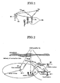
- a base station M1 is located at an observational point A whose coordinates are already known as a reference point.
- a rover station M2 is located at an observational point B whose coordinates to be sought are not yet known.
- the RTK positioning system moves the rover station M2 as required to another observational point whose coordinates to be sought next are not yet known.
- the base station M1 and the rover station M2 receive positioning satellite signals (radio waves) from an artificial satellite Sa.
- the rover station M2 performs analysis and processing in real-time simultaneously with the reception of the above signals.
- the RTK positioning system sequentially seeks the positional coordinates of the observational point B, which are not yet known.
- an area in which the rover station M2 can refer to a specific base station M1 (hereunder, referred to as the base station reference area) is about an radius 10 km, with the base station M1 placed at the center thereof. This is because an excessive distance between the base station M1 and the rover station M2 will make it impossible to ignore the influences of differences in the ionosphere and atmospheric layer at the observational point, which will lead to a deterioration of measurement accuracy.
- the rover station M2 in order to make it possible that the rover station M2 refers to correction data of the base station M1, it is necessary to transmit the correction data to the rover station M2 from the base station M1.
- This transmission requires a device that transmits the data from the base station M1 by a radio transmission of a specified frequency. Because of this, the base station M1 is provided with a transmission device (a transmitter Se having the output power of about 10 mW and the frequency of 400 MHz, for example), to always transmit the correction data.
- a radio receiver Sc capable of receiving the radio waves from the transmitter Se is installed on the side of the rover station M2, so that the rover station M2 can refer to the correction data transmitted.
- a satellite positioning data server Dsb as data transmission/reception media.
- rover station M2 Connected to the satellite positioning system, by way of the GPS positioning data server Dsb, are at least one rover station M2, a plurality of base stations M1 and M1', and communication devices Sx and Sy that establish communications between the rover station M2 and the base stations M1 and M1'.
- the base stations M1 and M1' are fixedly located at positions whose coordinates are already known.
- the base stations M1 and M1' receive radio waves from the artificial satellite Sa continuously or periodically, and acquire the correction data of the positions in which they are located.
- the measured correction data are transmitted continuously or periodically to the GPS positioning data server Dsb by the communication device Sx.
- the communication device Sx as the communication interface transmits the correction data at a high speed, and includes the base stations M1 and M2' that are located fixedly at already known positions. Accordingly, the communication device Sx as the communication interface is used in continuous connection with an exclusive network such as the WAN.
- the radio frequencies used for transmitting the correction data are generally set to be different at each of the base stations M1 and M1'.
- the reason is that when the radio coverage borders are adjacent, the base stations are difficult to be identified, which causes a measurement error.
- the radio coverage area has an overlap, there occur radio interferences in the overlapped area. In this case, a description is made of two base stations M1 and M1'. However, the same description holds good for over three base stations.
- the radio transmitters M1 thereof are set to individually different frequencies. Therefore, it becomes necessary to adjust the reception frequency of the rover station M2 in accordance with the base station used.
- a desirable base station is generally selected among the base stations M1, M1',..., and the frequency of the desirable base station is checked and adjusted before the task. Accordingly, when the rover station M2 moves over a referable area of a base station (M1, for example) into a referable area of another base station (M1', for example), the rover station M2 is bound to refer to the base stations M1, M1',..., which are different.
- the task should be always performed recognizing the relationship between the current position of the rover station M2 and the position of the base station (M1 or M1', etc.), which is inconvenient.
- a base station should be selected that is usable based on the number of satellites common to the base stations and rover stations and is in good condition for receiving the artificial satellite Sa. Then, the reception frequency should be appropriately set in accordance with the selected base station. This is also inconvenient.
- the communication is confined to one direction from the base stations M1, M1', .., to the rover station M2. Therefore, it is impossible to receive or transmit bi-directional data such as data for checking the condition of the rover station M2 from the base station M1. This is also inconvenient.
- IP address In case of a communication through a network, fixed addresses are needed to choose a communication partner.
- the fixed use of the IP address is finite, and obtaining it is limited and expensive.
- the IP address is dynamic and is modified at each access; therefore, the IP address cannot be used as a fixed address in selecting to connect a partner, which is inconvenient.
- the present system only needs an inherent ID in the IP-VPN, and it is possible to use an inherent number for a machine ID as an address and to designate a connection destination.
- the indirect observation method based on the public survey task manual (Geographical Survey Institute of Japan, technical data A1-No.228, June 2000, http//psgsv.gsi.go.jp/koukyou/rtk_manual/htm/mokuji.htm) requires delivering the correction data from one base station to two rover stations. Therefore, the task cannot be performed through a cellular phone network, which is inconvenient. For the foregoing reasons, there is a need for a survey system that can overcome the inconveniences.
- the present invention is directed to an RTK-GPS survey system that satisfies this need, and provides an RTK-GPS survey system capable of selecting a base station with less interference.
- a first aspect of the RTK-GPS survey system for performing an RTK-GPS survey comprises a server in an IP-VPN communication network for establishing communications between a plurality of satellite positioning devices as base station and a plurality of satellite positioning devices as rover stations, the base station transmitting correction data, the rover station receiving the correction data.
- the satellite positioning devices each includes at least a satellite positioning unit for receiving radio waves from artificial satellites, a communication unit for performing communications between the satellite positioning devices, and a control unit for controlling the satellite positioning unit and the communication unit; and the control unit of the rover station is capable of receiving interference information registered in the control unit of each satellite positioning device of the base stations, and selecting a base station for transmitting most appropriate correction data among the plurality of base stations.
- a second aspect of the RTK-GPS survey system for performing an RTK-GPS survey comprises a server in an IP-VPN communication network for establishing communications between a plurality of satellite positioning devices as base station and a plurality of satellite positioning devices as rover stations, the base station transmitting correction data, the rover station receiving the correction data.
- the satellite positioning devices each includes at least a satellite positioning unit for receiving radio waves from artificial satellites, a communication unit for performing communications between the satellite positioning devices, and a control unit for controlling the satellite positioning unit and the communication unit; and the control unit of the base station includes an estimate device for estimating an area in a sky map in which an S/N ratio of a received signal is lower than a reference value, and the control unit of the rover station removes correction data based on the radio waves from artificial satellites existing in the area in the sky map to perform an RTK-GPS processing.
- Fig. 3 is a whole configuration map illustrating an outline of the RTK-GPS survey system of the embodiment 1 relating to the present invention.
- the satellite positioning system includes a plurality of observational stations 15, 16 and 17 as a satellite positioning device capable of performing the RTK-GPS survey and one server 9 in a communication network 10.
- At least one of the observational stations is used as a base station that transmits correction data for the analysis and processing of measured locations, and at least one of the rest of the observational stations is used as a rover station that receives the correction data.
- each observational station includes a satellite positioning unit 11 that seeks the positional coordinates of its own by receiving the radio waves from the artificial satellite Sa, a communication unit 12 that performs communications between the observational stations, and a control unit 13 that controls the satellite positioning unit 11 and the communication unit 12.
- a reference numeral symbol 14 denotes a OPS antenna that receives the radio waves from the artificial satellite Sa.
- the control unit 13 includes a communication button 13A, a switch button 13B, a designation button 13C, and a display 13D.
- the firmware function incorporated into the control unit 13 may display a switch function button on the display 13D to thereby perform switching.
- the control unit 13 includes a hand-held PC.
- the control unit 13 has the function of setting and controlling the GPS receiver of the satellite positioning unit 11, and the function of setting and controlling the communication unit 12.
- the satellite positioning unit 11 generally uses four or more artificial satellites Sa to perform the position analysis, but is not restricted to this.
- the communication unit 12 has the function of transmitting, by the packet communication, the correction data wherein reception data from the artificial satellite Sa and already-known positional coordinates are combined (data of the so-called CMR or RTCM format, for example).
- the satellite positioning unit 11, communication unit 12, and control unit 13 are compactly integrated into one body.
- Fig. 3 illustrates three observational stations 15, 16 and 17. It is assumed that one of the three is used as a rover station 15, and that the remaining two are used as base stations 16, and 17.
- the satellite positioning unit 11 performs the function of seeking the positional coordinates of its own by receiving the radio waves from the artificial satellite Sa.
- the communication unit 12 performs the function of communicating between the observational stations through the server 9.
- An ID inherent to each of the observational stations is assigned to each communication unit 12, and the ID inherent to each communication unit 12 is registered in the server 9 to correspond with each observational station.
- the server 9 has the function of registering IDs and authentication.
- the communication network 10 is an IP-VPN in this embodiment, and each communication unit is a mobile cellular phone network as a radio transmitter-receiver.
- the inherent ID is a mobile cellular phone number, but may be a machine number inherent to each observational station.
- each communication unit 12 is connected to the communication network 10 through an IP communication network.
- each communication unit 12 is connected to the IP-VPN (internet protocol-virtual private network) by using a communication card for the mobile phone network.
- IP-VPN Internet protocol-virtual private network
- the IP-VPN is a service by which the public circuit can be used like a dedicated line, which is a well-known technique. That is, the IP-VPN is a VPN built up through a wide area IP network that a communication common carrier holds.
- a remote network can be operated in the same manner as it is connected to a LAN. Using the Internet will build up a virtually dedicated line, which is protected by using the authentication technique and password technique.
- the server 9 herein has the function of setting up a communication between one rover station 15 and the other two base stations 16 and 17.
- the server 9 carries out the functions of delivering packet data as the correction data, transmitting control commands, recording data, authenticating log-in IDs, and monitoring the communication network 10.
- the server 9 authenticates the ID inherent to the rover station 15 that is the communication originator and permits the rover station 15 to log-in. At the same time, the server 9 searches the IDs inherent to the base stations 16 and 17 that are the communication partners, and establishes the communication between the base station 16 or the base station 17 and the rover station 15.
- one rover station 15 can select either of the two base stations 16 and 17.
- the RTK-GPS survey system can enhance the communication speed as well as the security.
- the communication network 10 there is one rover station located in the communication network 10.
- the ID inherent to each of the plural rover stations is registered in the server 9, and a selection device capable of selecting the base stations is provided to the control unit 13 of the observational station used as the rover station, a specified base station can be selected among the plural base stations, even when a plurality of rover stations are present.
- an observational station is located at a reference point to perform setting operation of the base station.
- the server 9 existing in the communication network 10 performs the authentication by using the ID inherent to the communication unit, and determines whether or not the access is permitted.
- a rover station is located at a point whose positional coordinates are not yet known. Then, the initialization of the rover station is performed.
- the rover station Based on the measurement plan, the rover station is located at the observational point. While receiving the radio waves from the artificial satellite Sa, the rover station performs positioning by itself. In general, the information on the positional coordinates acquired by this positioning by itself basically includes errors of 20 - 100 m.
- the correction data of the base station selected by the rover station are delivered to the rover station through the server 9 and the communication network 10.
- the rover station receives the correction data of the base station that are requested through the server 9.
- the analysis and processing device of the control unit 13 analyzes the correction data together with the data received by the rover station to thereby correct the errors. This produces precise positional information.
- This correction will achieve the positioning accuracy of about 10 mm.
- the achieved result is recorded in the data memory of the control unit 13 provided with the rover station. After completing the operation, the processing of a map creation is performed in other places.
- a centralized analysis and processing unit (centralized terminal unit) 19A is provided to the communication network 10, which analyzes on-line the positioning data acquired by the satellite positioning device used as the rover station.
- An ID inherent to the centralized analysis and processing unit 19A is assigned, and is registered in the server 9 to establish the communication between the centralized analysis and processing unit 19A connected to the communication network 10 and the rover station through the server 9.
- the positioning data acquired by the static observation using the rover station are transmitted to the centralized analysis and processing unit 19A through the server 9, and are analyzed by the centralized analysis and processing unit 19A. This enables the base line analysis and processing.
- the base line analysis and processing unit 19A With the communication network 10, the base line analysis and processing becomes possible, without bringing back from a survey site to the office the observation materials of the satellite positioning unit 11, communication unit 12, and control unit 13 that make up the rover station, and without downloading the positioning data to the PC (personal computer).
- a centralized terminal unit 19B is provided with the communication network 10, which updates a firmware to perform the function of the control unit 13.
- An ID inherent to the terminal unit 19B is assigned, and is registered in the server 9 to establish the communication between the terminal unit 19B connected to the communication network 10 and each observational station through the server 9.
- the version up of the firmware of the control unit 13 becomes possible.
- Such configuration may be the one that enables the version up of the firmware of the satellite positioning unit 11, or that enables the version up of the firmware of the communication unit 12.
- the control unit 13 of each satellite positioning device incorporates an electromagnetic interference creation program.
- the electromagnetic interference information by the electromagnetic interference creation program may be attained by manually inputting the current conditions, or may be automatically created on the basis of reception information and satellite orbit information.
- the electromagnetic interference information registered in each control unit 13 of the base stations 16 and 17 is transmitted to the communication unit 12 of the rover station 15 from each communication unit 12 of the base stations 16 and 17.
- the control unit 13 of the rover station 15 creates a sky map on the basis of the electromagnetic interference information transmitted from the base stations 16 and 17, and displays the sky map on the display 13D.
- Fig. 6A, Fig. 6B, and Fig. 6C illustrate sky maps displayed on the display 13D of the rover station 15.
- Fig. 6A illustrates a sky map 20 created by the rover station 15 itself;
- Fig. 6B illustrates a sky map 21 of the base station 16, displayed on the display 13D of the rover station 15;
- Fig. 6C illustrates a sky map 22 of the base station 17, displayed on the display 13D of the rover station 15.
- the symbol Z0 denotes the zenith at each observational point
- the symbol Z1 denotes the altitude to the horizontal plane
- the symbol Z2 denotes the ring-like mask that conceals an area below a predetermined altitude
- the symbol Z3 denotes the area where exist electromagnetic interferences
- the ring-like mask Z2 is used to prohibit the reception of radio waves from the artificial satellites existing in the so-called low altitude, because the radio waves coming from the artificial satellites existing in the low altitude contain much noises.
- the sky map 20 created by the rover station 15 exist the artificial satellites Zs1 through Zs5; in the sky map 21 created by the base station exist the artificial satellites Zs2, Zs3, Zs4, Zs5, and Zs6; and in the sky map 22 created by the base station exist the artificial satellites Zs1 through Zs7.
- the operator compares the sky maps 20, 21, and 22 displayed on the display 13D of the rover station 15, and judges which one of the base stations 16 and 17 should be used.
- the operator selects the base station 17 that has the largest number of the common artificial satellites Zsi.
- the number of the artificial satellites of the rover station 15 is five, and the number of the common artificial satellites of the base station 17 is also five.
- control unit 13 of the rover station 15 receives the interference information registered in the control unit 13 of each satellite positioning device of the base stations 16 and 17, and selects a base station with less electromagnetic interferences out of the plural base stations 16 and 17. This is performed by pressing the designation button 13C, for example.
- the selection is made on the ground that which one of the base stations 16 and 17 has more artificial satellites of higher reception strength, and that which one of the base stations 16 and 17 is nearer to the rover station 15.
- the RTK survey should be carried out during a time zone when the number of the artificial satellites appearing in the sky becomes the largest, because the time zone can be obtained from the relation between the appearance estimate of the artificial satellites and the electromagnetic interference information.
- Fig. 7 through Fig. 11 illustrate sky maps for describing the embodiment 2, in which the electromagnetic interference information is created by using a program for automatically creating the electromagnetic interference information.
- each satellite positioning unit 11 receives the radio waves from the artificial satellites.
- the artificial satellite used for the survey orbits once for about 12 hours, in case of a GPS satellite.
- the orbit of the artificial satellite can be found, by receiving the radio waves transmitted from the artificial satellite passing the sky at the same observational point over 12 hours.
- Fig. 7 draws an orbit SR of the artificial satellite Sa in the sky map 23, which is created by the program for automatically creating the electromagnetic interference information incorporated in the control unit 13 of the base station 16 (or the base station 17) located at a certain observational point (in this case, the observational point A, for example).
- the multiple striae are drawn as the orbit SR in this drawing, because there are multiple artificial satellites Sa passing the sky.
- the orbit can be attained by the arithmetic operation of the orbit of each artificial satellite, based on the calendar information of each artificial satellite Sa and the positional information of the base station 16 (or the base station 17) placed at the observational point. It is assumed that the orbit in the sky map 23' of each artificial satellite attained by using the program for automatically creating the electromagnetic interference information is one illustrated in Fig. 8.
- Fig. 8 shows an original orbit SR drawn in the sky map 23 in case any electromagnetic interference does not exist, when the base station 16 or the base station 17 is located at the observational point A.
- Fig. 7 shows the sky map 23 of the actual observation result, which does not draw the right upper part of the striae of the orbit SR.
- the already mentioned ring-like mask Z2 is applied to the sky map 23.
- the sky map 23 as shown in Fig. 7 exists an area where the radio waves from the satellite Sa cannot be received, that is, the electromagnetic interference area Z3. This can be understood by contrasting the sky map 23 shown in Fig. 7 with the sky map 23' shown in Fig. 8.
- the program for automatically creating the electromagnetic interference information is attained the actual orbit of each artificial satellite Sa passing in the sky over the base station located at a certain observational point as well as the estimated orbit of each artificial satellite Sa at the observational point of each artificial satellite.
- the size and shape of the electromagnetic interference area Z3 in the sky map 23 acquired by the actual measurement at the certain observational point can be estimated, as shown in Fig. 10, by the difference between the actual orbit and the estimated orbit.
- the program for automatically creating the electromagnetic interference information makes the control unit 13 of the base station store the electromagnetic interference area Z3 thus attained. In response to a request from the rover station 15, the control unit 13 of the base station transmits the electromagnetic interference information.
- the sky map 23 automatically attained at the base station is displayed on the display 13D of the rover station 15. According to this, the rover station 15 can determine whether or not the base station should be used, by contrasting the sky map 20 created by itself with the sky map 23 transmitted to the base station.
- the actual orbit of each artificial satellite Sa is displayed on the display 13D of the control unit 13 of the base station.
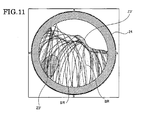
- Fig. 11 shows a sky map 24 which displays a noise interference area (hereunder, referred to as a high noise interference area), in which noise over a predetermined S/N ratio is superposed on the received radio waves.
- a noise interference area hereunder, referred to as a high noise interference area
- the base station is bound to receive the radio waves from the artificial satellite Sa, on which high noise is superposed.
- the system of this embodiment 3 incorporates a noise analysis program (noise interference area estimate program) into the control unit 13 of the base station, and makes the control unit 13 analyze the noise contained in the radio waves actually coming from the artificial satellite Sa to obtain a S/N ratio at each position on each orbit SR in the sky map 20.
- the system specifies a noise interference area Z3' whose S/N ratio is lower than a reference value, as shown in Fig. 11.
- the reference value may be set to an appropriate value for each satellite reception altitude. Alternatively, the system may also obtain the reference value based on the S/N ratio of all the satellites from which it actually receives the radio waves.
- the base station (base station 16, for example) transmits the S/N ratio area information on the noise interference area Z3' to the rover station (rover station 15, for example).
- An operation program which calculates the satellite number passing the noise interference area Z3' and the time zone thereof from the coming information (history information) of the artificial satellite Sa, is incorporated in the control unit 13 of the rover station.
- the radio waves from the artificial satellite passing the noise interference area Z3' are set not to be used in the RTK survey.
- the rover station will not perform the RTK survey using the radio waves from the artificial satellite passing the noise interference area Z3', even if the correction information transmitted from a selected base station contains the radio waves from an artificial satellite passing the noise interference area Z3'.
- the correction information transmitted from the selected base station contains the radio waves from the artificial satellite passing the noise interference area Z3', it is possible to estimate in advance the correction information containing high noises due to buildings and trees. As a result, a precise RTK survey can be realized by using only good quality correction information.
- the base station alone can automatically create the information on the electromagnetic interference area Z3 and the information on the noise interference area Z3'.
- a base station used for a long-term observation like a permanent base station, can in real-time update the information on the electromagnetic interference area Z3 and the information on the noise interference area Z3', even if there are environmental changes around the base station on the basis of the environmental changes, such as enlargement or relocation of buildings, growth of trees due to seasonal changes.
- the control unit of the rover station is capable of receiving interference information registered in the control unit of each satellite positioning device of the base stations to select a base station with less interference among the plurality of base stations, a most appropriate base station can be selected so that the number of satellites common to the base stations and rover stations is the maximum.
- the RTK survey task can be performed with interference noises removed.
Landscapes
- Engineering & Computer Science (AREA)
- Radar, Positioning & Navigation (AREA)
- Remote Sensing (AREA)
- Computer Networks & Wireless Communication (AREA)
- Physics & Mathematics (AREA)
- General Physics & Mathematics (AREA)
- Position Fixing By Use Of Radio Waves (AREA)
- Mobile Radio Communication Systems (AREA)
- Radio Relay Systems (AREA)
Applications Claiming Priority (1)
| Application Number | Priority Date | Filing Date | Title |
|---|---|---|---|
| JP2006136277A JP4912739B2 (ja) | 2006-05-16 | 2006-05-16 | Rtk−gps測量システム |
Publications (3)
| Publication Number | Publication Date |
|---|---|
| EP1857830A2 true EP1857830A2 (fr) | 2007-11-21 |
| EP1857830A3 EP1857830A3 (fr) | 2009-11-11 |
| EP1857830B1 EP1857830B1 (fr) | 2013-07-03 |
Family
ID=38441526
Family Applications (1)
| Application Number | Title | Priority Date | Filing Date |
|---|---|---|---|
| EP07009709.2A Not-in-force EP1857830B1 (fr) | 2006-05-16 | 2007-05-15 | Système d'inspection RTK-GPS |
Country Status (4)
| Country | Link |
|---|---|
| US (1) | US7482974B2 (fr) |
| EP (1) | EP1857830B1 (fr) |
| JP (1) | JP4912739B2 (fr) |
| CA (1) | CA2588619C (fr) |
Cited By (8)
| Publication number | Priority date | Publication date | Assignee | Title |
|---|---|---|---|---|
| CN104833994A (zh) * | 2015-04-15 | 2015-08-12 | 华东师范大学 | 一种基于自组网方式的rtk北斗定位系统及其方法 |
| EP2558879A4 (fr) * | 2010-04-12 | 2015-10-21 | Nokia Technologies Oy | Gestion de flux de données d'assistance périodique |
| CN106802426A (zh) * | 2017-01-19 | 2017-06-06 | 湖南北云科技有限公司 | 一种协作rtk定位方法及系统 |
| CN106840124A (zh) * | 2017-03-30 | 2017-06-13 | 中铁四局集团建筑工程有限公司 | 一种用于高层建筑快速测量放样的方法 |
| CN107071893A (zh) * | 2017-01-19 | 2017-08-18 | 湖南北云科技有限公司 | 一种蜂窝网络rtk定位方法及系统 |
| CN108474856A (zh) * | 2016-01-15 | 2018-08-31 | 松下知识产权经营株式会社 | Gnss校正数据分发装置、gnss校正数据分发系统以及gnss校正数据分发方法 |
| CN111836357A (zh) * | 2019-04-17 | 2020-10-27 | 华为技术有限公司 | 通信方法及装置 |
| WO2024194850A1 (fr) * | 2023-03-23 | 2024-09-26 | Ground Transportation Systems Canada Inc. | Systèmes et procédés de détermination de position de véhicule |
Families Citing this family (21)
| Publication number | Priority date | Publication date | Assignee | Title |
|---|---|---|---|---|
| CA2585141C (fr) * | 2004-10-29 | 2012-09-11 | Hitachi Zosen Corporation | Procede et systeme de positionnement relatif utilisant un satellite |
| JPWO2006046305A1 (ja) * | 2004-10-29 | 2008-05-22 | 日立造船株式会社 | 衛星を用いた相対計測方法および相対計測システム |
| US8078192B2 (en) * | 2008-04-22 | 2011-12-13 | Nokia Corporation | Supporting the use of a virtual reference station |
| JP5354717B2 (ja) * | 2008-11-06 | 2013-11-27 | 学校法人東京理科大学 | 変位計測システム、衛星信号受信装置および衛星測位方法 |
| US9322918B2 (en) | 2009-02-22 | 2016-04-26 | Trimble Navigation Limited | GNSS surveying methods and apparatus |
| JP5458617B2 (ja) * | 2009-03-19 | 2014-04-02 | カシオ計算機株式会社 | Gps受信装置、及びgps信号受信方法とプログラム |
| JP2010261867A (ja) * | 2009-05-08 | 2010-11-18 | Furuno Electric Co Ltd | レールふく進計測用gnss電波観測装置及びレールふく進計測システム |
| CN102235858A (zh) * | 2011-03-24 | 2011-11-09 | 广东省电力设计研究院 | 有编码rtk-gps输电线路平断面测量方法及系统 |
| US9821999B2 (en) * | 2012-12-28 | 2017-11-21 | Trimble Inc. | External GNSS receiver module with motion sensor suite for contextual inference of user activity |
| JP6302630B2 (ja) | 2013-06-14 | 2018-03-28 | 株式会社トプコン | Rtk測量作業に用いる準備システム |
| US9945955B2 (en) * | 2014-09-03 | 2018-04-17 | Glacial Ridge Technologies, LLC | Device for inputting RTK correction data to a GPS |
| JP6829800B2 (ja) * | 2017-02-02 | 2021-02-17 | 国際航業株式会社 | 受信機の適地判定方法、及び受信機の適地判定システム |
| CN108345010A (zh) * | 2018-02-12 | 2018-07-31 | 中设设计集团股份有限公司 | 基于北斗卫星信号及安卓应用的测量放样系统及放样方法 |
| CN108507452B (zh) * | 2018-03-21 | 2020-09-08 | 中铁建电气化局集团南方工程有限公司 | 一种客运专线接触网支柱侧面限界的测定方法 |
| JP2021056012A (ja) * | 2019-09-27 | 2021-04-08 | 株式会社トプコン | Gnss装置 |
| CN111132006A (zh) * | 2019-12-12 | 2020-05-08 | 南京苏美达智能技术有限公司 | 自行走设备的定位方法、系统及服务器 |
| CN112325846B (zh) * | 2020-10-21 | 2021-07-02 | 北京航空航天大学 | 一种rtk倾斜测量精度提升方法 |
| WO2022107941A1 (fr) * | 2020-11-22 | 2022-05-27 | 이상주 | Procédé de positionnement rtk de groupe à l'aide d'un dispositif terminal de référence temporaire |
| US11802971B2 (en) * | 2021-03-02 | 2023-10-31 | Qualcomm Incorporated | Real-time kinematic (RTK) and differential global navigation satellite system (DGNSS) corrections using multiple reference stations |
| CN117980779A (zh) * | 2021-09-29 | 2024-05-03 | 高通股份有限公司 | 差分全球导航卫星系统(dgnss)增强 |
| US20240168488A1 (en) * | 2022-11-17 | 2024-05-23 | Techtronic Cordless Gp | Determining a location to place a base station device used by a robotic garden tool |
Citations (3)
| Publication number | Priority date | Publication date | Assignee | Title |
|---|---|---|---|---|
| EP0779755A2 (fr) | 1995-12-13 | 1997-06-18 | Ntt Mobile Communications Network Inc. | Sélection de station de base d'un système cellulaire CDMA utilisant un canal sémaphore et le rapport signal/interférence reçu |
| US6185427B1 (en) | 1996-09-06 | 2001-02-06 | Snaptrack, Inc. | Distributed satellite position system processing and application network |
| US6329945B1 (en) | 2000-04-20 | 2001-12-11 | Novatel, Inc. | System for improved GPS accuracy using a sky map |
Family Cites Families (13)
| Publication number | Priority date | Publication date | Assignee | Title |
|---|---|---|---|---|
| JP3208202B2 (ja) * | 1992-12-03 | 2001-09-10 | 株式会社ソキア | キネマティック測量用制御装置 |
| JPH08122066A (ja) * | 1994-10-26 | 1996-05-17 | Sokkia Co Ltd | Gps受信装置 |
| JP3587912B2 (ja) * | 1995-09-22 | 2004-11-10 | 株式会社ソキア | Gps受信装置 |
| JP2001305213A (ja) * | 2000-04-27 | 2001-10-31 | Toa Harbor Works Co Ltd | リアルタイムキネマティックgps/glonass測位システムおよびリアルタイムキネマティックgps測位システムの初期化方法 |
| JP2001337151A (ja) * | 2000-05-29 | 2001-12-07 | Jekku:Kk | 観測支援システム及び記録媒体 |
| JP2002006026A (ja) * | 2000-06-27 | 2002-01-09 | Jekku:Kk | 目標位置誘導システム及び記録媒体 |
| JP2002311124A (ja) * | 2001-04-11 | 2002-10-23 | Mitsui & Co Ltd | 衛星測位システム |
| JP2002311123A (ja) * | 2001-04-11 | 2002-10-23 | Mitsui & Co Ltd | 衛星測位システム |
| US6985104B2 (en) * | 2002-07-29 | 2006-01-10 | Trimble Navigation Limited | Method and system for variable data rate transmission in RTK GPS survey system |
| JP2004239797A (ja) * | 2003-02-07 | 2004-08-26 | Topcon Corp | 衛星測位システム |
| US6879283B1 (en) * | 2003-02-21 | 2005-04-12 | Trimble Navigation Limited | Method and system for transmission of real-time kinematic satellite positioning system data |
| US7280534B2 (en) * | 2003-11-19 | 2007-10-09 | Lucent Technologies Inc. | Managed IP routing services for L2 overlay IP virtual private network (VPN) services |
| US7020555B1 (en) * | 2003-12-23 | 2006-03-28 | Trimble Navigation Limited | Subscription GPS information service system |
-
2006
- 2006-05-16 JP JP2006136277A patent/JP4912739B2/ja not_active Expired - Fee Related
-
2007
- 2007-05-14 CA CA2588619A patent/CA2588619C/fr not_active Expired - Fee Related
- 2007-05-15 EP EP07009709.2A patent/EP1857830B1/fr not_active Not-in-force
- 2007-05-15 US US11/803,504 patent/US7482974B2/en not_active Expired - Fee Related
Patent Citations (3)
| Publication number | Priority date | Publication date | Assignee | Title |
|---|---|---|---|---|
| EP0779755A2 (fr) | 1995-12-13 | 1997-06-18 | Ntt Mobile Communications Network Inc. | Sélection de station de base d'un système cellulaire CDMA utilisant un canal sémaphore et le rapport signal/interférence reçu |
| US6185427B1 (en) | 1996-09-06 | 2001-02-06 | Snaptrack, Inc. | Distributed satellite position system processing and application network |
| US6329945B1 (en) | 2000-04-20 | 2001-12-11 | Novatel, Inc. | System for improved GPS accuracy using a sky map |
Cited By (15)
| Publication number | Priority date | Publication date | Assignee | Title |
|---|---|---|---|---|
| EP2558879A4 (fr) * | 2010-04-12 | 2015-10-21 | Nokia Technologies Oy | Gestion de flux de données d'assistance périodique |
| US9519042B2 (en) | 2010-04-12 | 2016-12-13 | Nokia Technologies Oy | Periodic assistance data flow control |
| CN104833994B (zh) * | 2015-04-15 | 2017-06-16 | 华东师范大学 | 一种基于自组网方式的rtk北斗定位系统及其方法 |
| CN104833994A (zh) * | 2015-04-15 | 2015-08-12 | 华东师范大学 | 一种基于自组网方式的rtk北斗定位系统及其方法 |
| CN108474856A (zh) * | 2016-01-15 | 2018-08-31 | 松下知识产权经营株式会社 | Gnss校正数据分发装置、gnss校正数据分发系统以及gnss校正数据分发方法 |
| US11143762B2 (en) | 2016-01-15 | 2021-10-12 | Panasonic Intellectual Property Management Co., Ltd. | GNSS correction data distribution device, GNSS correction data distribution system, and GNSS correction data distribution method |
| EP3404445A4 (fr) * | 2016-01-15 | 2019-01-02 | Panasonic Intellectual Property Management Co., Ltd. | Dispositif de distribution de données de correction de système mondial de navigation par satellite (gnss), système de distribution de données de correction gnss, et procédé de distribution de données de correction gnss |
| CN107071893A (zh) * | 2017-01-19 | 2017-08-18 | 湖南北云科技有限公司 | 一种蜂窝网络rtk定位方法及系统 |
| CN106802426B (zh) * | 2017-01-19 | 2019-08-09 | 湖南北云科技有限公司 | 一种协作rtk定位方法及系统 |
| CN107071893B (zh) * | 2017-01-19 | 2020-04-28 | 湖南北云科技有限公司 | 一种蜂窝网络rtk定位方法及系统 |
| CN106802426A (zh) * | 2017-01-19 | 2017-06-06 | 湖南北云科技有限公司 | 一种协作rtk定位方法及系统 |
| CN106840124A (zh) * | 2017-03-30 | 2017-06-13 | 中铁四局集团建筑工程有限公司 | 一种用于高层建筑快速测量放样的方法 |
| CN106840124B (zh) * | 2017-03-30 | 2019-07-05 | 中铁四局集团建筑工程有限公司 | 一种用于高层建筑快速测量放样的方法 |
| CN111836357A (zh) * | 2019-04-17 | 2020-10-27 | 华为技术有限公司 | 通信方法及装置 |
| WO2024194850A1 (fr) * | 2023-03-23 | 2024-09-26 | Ground Transportation Systems Canada Inc. | Systèmes et procédés de détermination de position de véhicule |
Also Published As
| Publication number | Publication date |
|---|---|
| US20070268179A1 (en) | 2007-11-22 |
| US7482974B2 (en) | 2009-01-27 |
| EP1857830B1 (fr) | 2013-07-03 |
| EP1857830A3 (fr) | 2009-11-11 |
| CA2588619A1 (fr) | 2007-11-16 |
| CA2588619C (fr) | 2011-11-08 |
| JP2007309667A (ja) | 2007-11-29 |
| JP4912739B2 (ja) | 2012-04-11 |
Similar Documents
| Publication | Publication Date | Title |
|---|---|---|
| EP1857830B1 (fr) | Système d'inspection RTK-GPS | |
| US7460065B2 (en) | RTK-GPS surveying system | |
| CN100374874C (zh) | 用于确定发射机与移动通信设备位置的方法和设备 | |
| US9554247B2 (en) | Techniques for computing location of a mobile device based on observed Wi-Fi access points | |
| US9609617B2 (en) | Locating electromagnetic signal sources | |
| US6289279B1 (en) | Positioning system, method, and device for obtaining information about a current position | |
| US20130172005A1 (en) | Calculating wi-fi access point locations using wave of discovery | |
| EP2894896A1 (fr) | Procédé et système d'acquisition d'informations d'ingénierie de station de base | |
| CN107809797A (zh) | 一种对终端进行定位的方法及装置 | |
| KR20120064151A (ko) | 실내외 연속 측위를 통한 단말의 위치 표시 방법 | |
| KR20090036026A (ko) | pCell 데이터베이스를 업데이트하는 서버, 방법 및시스템 | |
| Lyle et al. | Texas Department of Transportation, Dallas District Differential Global Positioning System Real-Time Spatial Reference Frame Network | |
| MXPA00007092A (en) | Positioning system, positioning method and positioning device |
Legal Events
| Date | Code | Title | Description |
|---|---|---|---|
| PUAI | Public reference made under article 153(3) epc to a published international application that has entered the european phase |
Free format text: ORIGINAL CODE: 0009012 |
|
| AK | Designated contracting states |
Kind code of ref document: A2 Designated state(s): AT BE BG CH CY CZ DE DK EE ES FI FR GB GR HU IE IS IT LI LT LU LV MC MT NL PL PT RO SE SI SK TR |
|
| AX | Request for extension of the european patent |
Extension state: AL BA HR MK YU |
|
| PUAL | Search report despatched |
Free format text: ORIGINAL CODE: 0009013 |
|
| AK | Designated contracting states |
Kind code of ref document: A3 Designated state(s): AT BE BG CH CY CZ DE DK EE ES FI FR GB GR HU IE IS IT LI LT LU LV MC MT NL PL PT RO SE SI SK TR |
|
| AX | Request for extension of the european patent |
Extension state: AL BA HR MK RS |
|
| 17P | Request for examination filed |
Effective date: 20100414 |
|
| 17Q | First examination report despatched |
Effective date: 20100525 |
|
| AKX | Designation fees paid |
Designated state(s): AT BE BG CH CY CZ DE DK EE ES FI FR GB GR HU IE IS IT LI LT LU LV MC MT NL PL PT RO SE SI SK TR |
|
| REG | Reference to a national code |
Ref country code: DE Ref legal event code: R079 Ref document number: 602007031344 Country of ref document: DE Free format text: PREVIOUS MAIN CLASS: G01S0001000000 Ipc: G01S0019040000 |
|
| GRAP | Despatch of communication of intention to grant a patent |
Free format text: ORIGINAL CODE: EPIDOSNIGR1 |
|
| RIC1 | Information provided on ipc code assigned before grant |
Ipc: G01S 19/04 20100101AFI20121206BHEP Ipc: G01S 19/07 20100101ALI20121206BHEP |
|
| GRAS | Grant fee paid |
Free format text: ORIGINAL CODE: EPIDOSNIGR3 |
|
| GRAA | (expected) grant |
Free format text: ORIGINAL CODE: 0009210 |
|
| AK | Designated contracting states |
Kind code of ref document: B1 Designated state(s): AT BE BG CH CY CZ DE DK EE ES FI FR GB GR HU IE IS IT LI LT LU LV MC MT NL PL PT RO SE SI SK TR |
|
| REG | Reference to a national code |
Ref country code: GB Ref legal event code: FG4D |
|
| REG | Reference to a national code |
Ref country code: AT Ref legal event code: REF Ref document number: 620075 Country of ref document: AT Kind code of ref document: T Effective date: 20130715 Ref country code: CH Ref legal event code: EP |
|
| REG | Reference to a national code |
Ref country code: IE Ref legal event code: FG4D |
|
| REG | Reference to a national code |
Ref country code: DE Ref legal event code: R096 Ref document number: 602007031344 Country of ref document: DE Effective date: 20130829 |
|
| REG | Reference to a national code |
Ref country code: CH Ref legal event code: NV Representative=s name: BRAUNPAT BRAUN EDER AG, CH |
|
| PG25 | Lapsed in a contracting state [announced via postgrant information from national office to epo] |
Ref country code: SI Free format text: LAPSE BECAUSE OF FAILURE TO SUBMIT A TRANSLATION OF THE DESCRIPTION OR TO PAY THE FEE WITHIN THE PRESCRIBED TIME-LIMIT Effective date: 20130703 |
|
| REG | Reference to a national code |
Ref country code: AT Ref legal event code: MK05 Ref document number: 620075 Country of ref document: AT Kind code of ref document: T Effective date: 20130703 |
|
| REG | Reference to a national code |
Ref country code: NL Ref legal event code: VDEP Effective date: 20130703 |
|
| REG | Reference to a national code |
Ref country code: LT Ref legal event code: MG4D |
|
| PG25 | Lapsed in a contracting state [announced via postgrant information from national office to epo] |
Ref country code: PT Free format text: LAPSE BECAUSE OF FAILURE TO SUBMIT A TRANSLATION OF THE DESCRIPTION OR TO PAY THE FEE WITHIN THE PRESCRIBED TIME-LIMIT Effective date: 20131104 Ref country code: IS Free format text: LAPSE BECAUSE OF FAILURE TO SUBMIT A TRANSLATION OF THE DESCRIPTION OR TO PAY THE FEE WITHIN THE PRESCRIBED TIME-LIMIT Effective date: 20131103 Ref country code: CY Free format text: LAPSE BECAUSE OF FAILURE TO SUBMIT A TRANSLATION OF THE DESCRIPTION OR TO PAY THE FEE WITHIN THE PRESCRIBED TIME-LIMIT Effective date: 20130703 Ref country code: LT Free format text: LAPSE BECAUSE OF FAILURE TO SUBMIT A TRANSLATION OF THE DESCRIPTION OR TO PAY THE FEE WITHIN THE PRESCRIBED TIME-LIMIT Effective date: 20130703 Ref country code: AT Free format text: LAPSE BECAUSE OF FAILURE TO SUBMIT A TRANSLATION OF THE DESCRIPTION OR TO PAY THE FEE WITHIN THE PRESCRIBED TIME-LIMIT Effective date: 20130703 Ref country code: BE Free format text: LAPSE BECAUSE OF FAILURE TO SUBMIT A TRANSLATION OF THE DESCRIPTION OR TO PAY THE FEE WITHIN THE PRESCRIBED TIME-LIMIT Effective date: 20130703 Ref country code: SE Free format text: LAPSE BECAUSE OF FAILURE TO SUBMIT A TRANSLATION OF THE DESCRIPTION OR TO PAY THE FEE WITHIN THE PRESCRIBED TIME-LIMIT Effective date: 20130703 |
|
| PG25 | Lapsed in a contracting state [announced via postgrant information from national office to epo] |
Ref country code: ES Free format text: LAPSE BECAUSE OF FAILURE TO SUBMIT A TRANSLATION OF THE DESCRIPTION OR TO PAY THE FEE WITHIN THE PRESCRIBED TIME-LIMIT Effective date: 20131014 Ref country code: LV Free format text: LAPSE BECAUSE OF FAILURE TO SUBMIT A TRANSLATION OF THE DESCRIPTION OR TO PAY THE FEE WITHIN THE PRESCRIBED TIME-LIMIT Effective date: 20130703 Ref country code: GR Free format text: LAPSE BECAUSE OF FAILURE TO SUBMIT A TRANSLATION OF THE DESCRIPTION OR TO PAY THE FEE WITHIN THE PRESCRIBED TIME-LIMIT Effective date: 20131004 Ref country code: FI Free format text: LAPSE BECAUSE OF FAILURE TO SUBMIT A TRANSLATION OF THE DESCRIPTION OR TO PAY THE FEE WITHIN THE PRESCRIBED TIME-LIMIT Effective date: 20130703 Ref country code: PL Free format text: LAPSE BECAUSE OF FAILURE TO SUBMIT A TRANSLATION OF THE DESCRIPTION OR TO PAY THE FEE WITHIN THE PRESCRIBED TIME-LIMIT Effective date: 20130703 Ref country code: NL Free format text: LAPSE BECAUSE OF FAILURE TO SUBMIT A TRANSLATION OF THE DESCRIPTION OR TO PAY THE FEE WITHIN THE PRESCRIBED TIME-LIMIT Effective date: 20130703 |
|
| PG25 | Lapsed in a contracting state [announced via postgrant information from national office to epo] |
Ref country code: CZ Free format text: LAPSE BECAUSE OF FAILURE TO SUBMIT A TRANSLATION OF THE DESCRIPTION OR TO PAY THE FEE WITHIN THE PRESCRIBED TIME-LIMIT Effective date: 20130703 Ref country code: RO Free format text: LAPSE BECAUSE OF FAILURE TO SUBMIT A TRANSLATION OF THE DESCRIPTION OR TO PAY THE FEE WITHIN THE PRESCRIBED TIME-LIMIT Effective date: 20130703 Ref country code: SK Free format text: LAPSE BECAUSE OF FAILURE TO SUBMIT A TRANSLATION OF THE DESCRIPTION OR TO PAY THE FEE WITHIN THE PRESCRIBED TIME-LIMIT Effective date: 20130703 Ref country code: DK Free format text: LAPSE BECAUSE OF FAILURE TO SUBMIT A TRANSLATION OF THE DESCRIPTION OR TO PAY THE FEE WITHIN THE PRESCRIBED TIME-LIMIT Effective date: 20130703 Ref country code: EE Free format text: LAPSE BECAUSE OF FAILURE TO SUBMIT A TRANSLATION OF THE DESCRIPTION OR TO PAY THE FEE WITHIN THE PRESCRIBED TIME-LIMIT Effective date: 20130703 |
|
| PLBE | No opposition filed within time limit |
Free format text: ORIGINAL CODE: 0009261 |
|
| STAA | Information on the status of an ep patent application or granted ep patent |
Free format text: STATUS: NO OPPOSITION FILED WITHIN TIME LIMIT |
|
| PG25 | Lapsed in a contracting state [announced via postgrant information from national office to epo] |
Ref country code: IT Free format text: LAPSE BECAUSE OF FAILURE TO SUBMIT A TRANSLATION OF THE DESCRIPTION OR TO PAY THE FEE WITHIN THE PRESCRIBED TIME-LIMIT Effective date: 20130703 |
|
| 26N | No opposition filed |
Effective date: 20140404 |
|
| REG | Reference to a national code |
Ref country code: DE Ref legal event code: R097 Ref document number: 602007031344 Country of ref document: DE Effective date: 20140404 |
|
| PG25 | Lapsed in a contracting state [announced via postgrant information from national office to epo] |
Ref country code: LU Free format text: LAPSE BECAUSE OF FAILURE TO SUBMIT A TRANSLATION OF THE DESCRIPTION OR TO PAY THE FEE WITHIN THE PRESCRIBED TIME-LIMIT Effective date: 20140515 |
|
| GBPC | Gb: european patent ceased through non-payment of renewal fee |
Effective date: 20140515 |
|
| PG25 | Lapsed in a contracting state [announced via postgrant information from national office to epo] |
Ref country code: MC Free format text: LAPSE BECAUSE OF FAILURE TO SUBMIT A TRANSLATION OF THE DESCRIPTION OR TO PAY THE FEE WITHIN THE PRESCRIBED TIME-LIMIT Effective date: 20130703 |
|
| REG | Reference to a national code |
Ref country code: IE Ref legal event code: MM4A |
|
| REG | Reference to a national code |
Ref country code: FR Ref legal event code: ST Effective date: 20150130 |
|
| PG25 | Lapsed in a contracting state [announced via postgrant information from national office to epo] |
Ref country code: IE Free format text: LAPSE BECAUSE OF NON-PAYMENT OF DUE FEES Effective date: 20140515 |
|
| PG25 | Lapsed in a contracting state [announced via postgrant information from national office to epo] |
Ref country code: GB Free format text: LAPSE BECAUSE OF NON-PAYMENT OF DUE FEES Effective date: 20140515 Ref country code: FR Free format text: LAPSE BECAUSE OF NON-PAYMENT OF DUE FEES Effective date: 20140602 |
|
| PGFP | Annual fee paid to national office [announced via postgrant information from national office to epo] |
Ref country code: DE Payment date: 20150512 Year of fee payment: 9 Ref country code: CH Payment date: 20150512 Year of fee payment: 9 |
|
| PG25 | Lapsed in a contracting state [announced via postgrant information from national office to epo] |
Ref country code: MT Free format text: LAPSE BECAUSE OF FAILURE TO SUBMIT A TRANSLATION OF THE DESCRIPTION OR TO PAY THE FEE WITHIN THE PRESCRIBED TIME-LIMIT Effective date: 20130703 |
|
| PG25 | Lapsed in a contracting state [announced via postgrant information from national office to epo] |
Ref country code: BG Free format text: LAPSE BECAUSE OF FAILURE TO SUBMIT A TRANSLATION OF THE DESCRIPTION OR TO PAY THE FEE WITHIN THE PRESCRIBED TIME-LIMIT Effective date: 20130703 |
|
| PG25 | Lapsed in a contracting state [announced via postgrant information from national office to epo] |
Ref country code: HU Free format text: LAPSE BECAUSE OF FAILURE TO SUBMIT A TRANSLATION OF THE DESCRIPTION OR TO PAY THE FEE WITHIN THE PRESCRIBED TIME-LIMIT; INVALID AB INITIO Effective date: 20070515 Ref country code: TR Free format text: LAPSE BECAUSE OF FAILURE TO SUBMIT A TRANSLATION OF THE DESCRIPTION OR TO PAY THE FEE WITHIN THE PRESCRIBED TIME-LIMIT Effective date: 20130703 |
|
| REG | Reference to a national code |
Ref country code: DE Ref legal event code: R119 Ref document number: 602007031344 Country of ref document: DE |
|
| REG | Reference to a national code |
Ref country code: CH Ref legal event code: PL |
|
| PG25 | Lapsed in a contracting state [announced via postgrant information from national office to epo] |
Ref country code: LI Free format text: LAPSE BECAUSE OF NON-PAYMENT OF DUE FEES Effective date: 20160531 Ref country code: CH Free format text: LAPSE BECAUSE OF NON-PAYMENT OF DUE FEES Effective date: 20160531 |
|
| PG25 | Lapsed in a contracting state [announced via postgrant information from national office to epo] |
Ref country code: DE Free format text: LAPSE BECAUSE OF NON-PAYMENT OF DUE FEES Effective date: 20161201 |