EP1858111A1 - Fahrzeugkomponente und Verfahren zur Montage von einer Fahrzeugkomponente - Google Patents
Fahrzeugkomponente und Verfahren zur Montage von einer Fahrzeugkomponente Download PDFInfo
- Publication number
- EP1858111A1 EP1858111A1 EP07108104A EP07108104A EP1858111A1 EP 1858111 A1 EP1858111 A1 EP 1858111A1 EP 07108104 A EP07108104 A EP 07108104A EP 07108104 A EP07108104 A EP 07108104A EP 1858111 A1 EP1858111 A1 EP 1858111A1
- Authority
- EP
- European Patent Office
- Prior art keywords
- panel
- component
- gripping element
- fastening means
- hole
- Prior art date
- Legal status (The legal status is an assumption and is not a legal conclusion. Google has not performed a legal analysis and makes no representation as to the accuracy of the status listed.)
- Ceased
Links
Images
Classifications
-
- H—ELECTRICITY
- H01—ELECTRIC ELEMENTS
- H01Q—ANTENNAS, i.e. RADIO AERIALS
- H01Q1/00—Details of, or arrangements associated with, antennas
- H01Q1/12—Supports; Mounting means
- H01Q1/1207—Supports; Mounting means for fastening a rigid aerial element
- H01Q1/1214—Supports; Mounting means for fastening a rigid aerial element through a wall
-
- B—PERFORMING OPERATIONS; TRANSPORTING
- B60—VEHICLES IN GENERAL
- B60R—VEHICLES, VEHICLE FITTINGS, OR VEHICLE PARTS, NOT OTHERWISE PROVIDED FOR
- B60R11/00—Arrangements for holding or mounting articles, not otherwise provided for
- B60R11/02—Arrangements for holding or mounting articles, not otherwise provided for for radio sets, television sets, telephones, or the like; Arrangement of controls thereof
- B60R11/0264—Arrangements for holding or mounting articles, not otherwise provided for for radio sets, television sets, telephones, or the like; Arrangement of controls thereof for control means
-
- H—ELECTRICITY
- H01—ELECTRIC ELEMENTS
- H01Q—ANTENNAS, i.e. RADIO AERIALS
- H01Q1/00—Details of, or arrangements associated with, antennas
- H01Q1/27—Adaptation for use in or on movable bodies
- H01Q1/32—Adaptation for use in or on road or rail vehicles
- H01Q1/325—Adaptation for use in or on road or rail vehicles characterised by the location of the antenna on the vehicle
- H01Q1/3275—Adaptation for use in or on road or rail vehicles characterised by the location of the antenna on the vehicle mounted on a horizontal surface of the vehicle, e.g. on roof, hood, trunk
-
- B—PERFORMING OPERATIONS; TRANSPORTING
- B60—VEHICLES IN GENERAL
- B60R—VEHICLES, VEHICLE FITTINGS, OR VEHICLE PARTS, NOT OTHERWISE PROVIDED FOR
- B60R11/00—Arrangements for holding or mounting articles, not otherwise provided for
- B60R2011/0001—Arrangements for holding or mounting articles, not otherwise provided for characterised by position
- B60R2011/0003—Arrangements for holding or mounting articles, not otherwise provided for characterised by position inside the vehicle
- B60R2011/0007—Mid-console
Definitions
- the present invention generally relates to automotive components and methods for mounting of such components.
- rooftop antennas which are common in the industry, require a hole in the roof.
- the antennas have fly leads which need to be fed through this hole in the roof. From the inside the antenna is fixed with a nut which has to cut out to allow the fly leads to bend backwards.
- a problem is that the assembler has great difficulty to reach the hole on the roof. It is impossible to feed through the fly leads and from the inside is not possible to fix the not without somebody from the outside holding down the antenna.
- US 6,879,301 B2 describes a waterproof automotive antenna mounting assembly gasket comprising a base having a plurality of apertures and a mounting hole disposed therein, a generally sloped outer casing extending upward from the base, an inner casing connected along the bottom portion of the outer casing and positioned interior to the outer casing, the gap positioned between the bottom portion of the inner casing and the base, a plurality of compressible tabs extending inwardly from the inner casing and aligned with the apertures in the base, the channel disposed in between the inner and outer casings, a plurality gripping members disposed on the base plate, a sealing interface disposed on the base and an anti-rotation hole disposed on the base.
- the anti-rotation hole aligns with the corresponding hole attached to a secondary surface.
- Assembly of this antenna mounting assembly requires it downward push of the antenna unit and the attachment assembly through an opening in the panel.
- the attachment assembly is inserted through the opening in the panel while resilient fingers of a snap ring compress radially inward.
- the tips of the fingers extend within arcuate between the tabs of the base plate. Once the snap ring passes fully through the opening the fingers spread radially outward.
- the tips of the fingers which are preferably bent inwardly, abut against the interior surface of the panel, thereby locking the attachment assembly in place. Further adjustments can be made by rotating a jam nut.
- This mounting assembly requires several parts and it is also necessary to make final adjustments by use of the jam nut. If the antenna is to be mounted in a centered manner on a rooftop, it is impossible for the assembler push the antenna mounting assembly downward through the opening in the rooftop and at the same time adjust the attachment with the jam nut.
- an object of the present invention to provide an automotive component and method for mounting of an automotive component, which allow an easy assembly by a single person, especially on the panel which cannot be easily accessed by single person from both sides, for example a rooftop or trunk lid of an automobile.
- the component should also comprise as few parts as possible to reduce costs.
- the component allows the component to be put on one side of the panel, for example the rooftop, and then using the fastening means from the other side of the panel while pulling the component into place via the gripping element. Therefore it is not necessary for a second person to push the component downward on the panel. Also the component does not need the relative complex arrangement known from the US 6,879,301 described above, which also has several parts.
- the automotive component the gripping element extends through a hole in the panel to the other side of the panel.
- the gripping element is formed to allow for non-positive gripping by an assembler and/or with a tool. Further the gripping element preferably has an enlarged head.
- the gripping element has an undercut, which can be formed by a mushroom type shape of the head of the gripping element.
- the gripping element is formed by part of a keying means including a locator pin which extends through a second hole in the panel, which is displaced from the first hole, so that rotation of the component is prevented, or even by the locator pin itself. Therefore no additional parts are necessary.
- the automotive component of the invention is preferably an antenna, especially a roof top or trunk lid antenna, e.g. an AM/FM, GPS or GSM antenna .
- a roof top or trunk lid antenna e.g. an AM/FM, GPS or GSM antenna .
- the component is not limited to an antenna, as the invention can be applied to almost every component that is intended to be fixed to the outside of a vehicle by fastening means on the inside.
- the invention also relates to a method for mounting of an automotive component to one side of a panel by fastening means on the other side of the panel comprising the following steps:
- the gripping element is pulled by use of a tool.
- the gripping element is pulled in a non-positive manner, which may be allowed, when the gripping element is formed with an enlarged head, an undercut or a head with a mushroom type shape for non-positive engagement.
- the gripping element is formed by the locator pin.
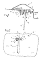
- an antenna 1 which consists of a hollow antenna casing 2 with a streamlined form, which is to be mounted on the rooftop of an automobile and covers the antenna parts.
- the antenna 1 is a GPS/GSM antenna. It will be appreciated that the method of attachment of the present embodiment may be used with any type of antenna and associated cover or base unit or with any other device or object that is intended to be affixed to a panel.
- the antenna casing 2 has a flat base plate 3, which is to be placed on the roof panel 10. From the flat base plate 3 threaded fastening means in form of a threaded bolt 4 extend outwards, so as to extend through a corresponding hole in the roof panel 10.
- connection means 5, 6 for connecting the antenna with the corresponding electrical parts within the vehicle.
- the separate electrical connection means 5, 6 allow for a convenient electrical connection as the fly leads must not be passed through the threaded bolt 4, as is usually the case.
- locator pin 7 Also extending outwards from the flat base plate 3 there are a keying means and form of the locator pin 7, which is somewhat displaced from the threaded bolt 4, which also extends through a corresponding hole in the roof panel 10 in and therefore prevents rotation of the antenna 1 and also allows for its correct positioning.
- the locator pin 7 has a head 8 with the form of a mushroom and is connected to the locator pin 7 via an undercut 9, which extends radially outward from the axis of the locator pin 7, i.e. has a cylindrical form.
- the antenna 1 is placed on the roof panel 10 with its appropriate orientation, which is predefined by the holes in the roof panel 10 and the location of the threaded bolt 4 and the locator pin 7.
- Both the threaded bolt 4 and the locator pin 7 extend through their corresponding holes in the roof panel 10, as can be seen in figure 2, in which the inside 10 of the roof panel 10 is shown.
- the threaded bolt 4 is engaged with the second fastening means in form of a threaded nut 11, with a washer 12 fitted in between the inside of the roof panel 10 and the nut 11.
- the tool 13 has a tool head 15, which is bent by ca. 90° to a handle 14 and has a recess 16 corresponding to the undercut 9, so that the head 8 of the locator pin may be gripped with tool 13.
Landscapes
- Engineering & Computer Science (AREA)
- Mechanical Engineering (AREA)
- Remote Sensing (AREA)
- Support Of Aerials (AREA)
- Fittings On The Vehicle Exterior For Carrying Loads, And Devices For Holding Or Mounting Articles (AREA)
Priority Applications (1)
| Application Number | Priority Date | Filing Date | Title |
|---|---|---|---|
| EP07108104A EP1858111A1 (de) | 2006-05-16 | 2007-05-14 | Fahrzeugkomponente und Verfahren zur Montage von einer Fahrzeugkomponente |
Applications Claiming Priority (2)
| Application Number | Priority Date | Filing Date | Title |
|---|---|---|---|
| EP06113989 | 2006-05-16 | ||
| EP07108104A EP1858111A1 (de) | 2006-05-16 | 2007-05-14 | Fahrzeugkomponente und Verfahren zur Montage von einer Fahrzeugkomponente |
Publications (1)
| Publication Number | Publication Date |
|---|---|
| EP1858111A1 true EP1858111A1 (de) | 2007-11-21 |
Family
ID=38175584
Family Applications (1)
| Application Number | Title | Priority Date | Filing Date |
|---|---|---|---|
| EP07108104A Ceased EP1858111A1 (de) | 2006-05-16 | 2007-05-14 | Fahrzeugkomponente und Verfahren zur Montage von einer Fahrzeugkomponente |
Country Status (1)
| Country | Link |
|---|---|
| EP (1) | EP1858111A1 (de) |
Cited By (2)
| Publication number | Priority date | Publication date | Assignee | Title |
|---|---|---|---|---|
| WO2017182969A1 (en) * | 2016-04-19 | 2017-10-26 | Magna Exteriors Inc. | Locator guide extension |
| CN113547990A (zh) * | 2021-09-06 | 2021-10-26 | 深圳市锐思华创技术有限公司 | 一种适用于光学显示的塑料镜片转动装置 |
Citations (3)
| Publication number | Priority date | Publication date | Assignee | Title |
|---|---|---|---|---|
| DE19732288A1 (de) * | 1997-07-26 | 1999-02-11 | Bayerische Motoren Werke Ag | Verfahren zum Herstellen eines Dachgepäckträgers, insbesondere einer Reling |
| EP1528624A1 (de) * | 2003-11-03 | 2005-05-04 | Delphi Technologies, Inc. | Antennenanordnung |
| JP2006111200A (ja) * | 2004-10-18 | 2006-04-27 | Yokowo Co Ltd | アンテナベース取付構造 |
-
2007
- 2007-05-14 EP EP07108104A patent/EP1858111A1/de not_active Ceased
Patent Citations (4)
| Publication number | Priority date | Publication date | Assignee | Title |
|---|---|---|---|---|
| DE19732288A1 (de) * | 1997-07-26 | 1999-02-11 | Bayerische Motoren Werke Ag | Verfahren zum Herstellen eines Dachgepäckträgers, insbesondere einer Reling |
| EP1528624A1 (de) * | 2003-11-03 | 2005-05-04 | Delphi Technologies, Inc. | Antennenanordnung |
| JP2006111200A (ja) * | 2004-10-18 | 2006-04-27 | Yokowo Co Ltd | アンテナベース取付構造 |
| US20060109186A1 (en) * | 2004-10-18 | 2006-05-25 | Yokowo Co., Ltd. | Structure for mounting antenna base on vehicle body |
Cited By (3)
| Publication number | Priority date | Publication date | Assignee | Title |
|---|---|---|---|---|
| WO2017182969A1 (en) * | 2016-04-19 | 2017-10-26 | Magna Exteriors Inc. | Locator guide extension |
| US11143228B2 (en) | 2016-04-19 | 2021-10-12 | Magna Exteriors Inc. | Locator guide extension |
| CN113547990A (zh) * | 2021-09-06 | 2021-10-26 | 深圳市锐思华创技术有限公司 | 一种适用于光学显示的塑料镜片转动装置 |
Similar Documents
| Publication | Publication Date | Title |
|---|---|---|
| US7212168B2 (en) | Quick-attach automotive antenna mounting assembly | |
| US6007136A (en) | Modular visor attachment fastener | |
| EP1858110B1 (de) | An einer Platte angebrachte Befestigungs-und Verbindungsvorrichtung für ein Fahrzeugantennenmodul | |
| US6762727B2 (en) | Quick-attach, single-sided automotive antenna attachment assembly | |
| EP1552579B1 (de) | Antennenanbringvorrichtungen | |
| US7002523B2 (en) | Antenna device | |
| US20050135896A1 (en) | Push-on screw-off attachment device | |
| EP0754603A1 (de) | Luftsack-Aufblasmodul zur Schnappbefestigung an einem Lenkrad | |
| US6735824B2 (en) | Accessory mounting mechanism | |
| EP2120284A1 (de) | Haltevorrichtung für eine Antenne und verfahren mit Befestigungskrallen und/oder Bajonettverriegelung | |
| US20190017531A1 (en) | Connecting Device to Antenna Housings | |
| HK1223742A1 (zh) | 车顶天线在车身顶棚上的固定结构 | |
| US6540251B1 (en) | Side airbag retention system and fastener | |
| EP0743461A1 (de) | Montagevorrichtung | |
| EP1608879B1 (de) | Befestigungsmittel | |
| EP1858111A1 (de) | Fahrzeugkomponente und Verfahren zur Montage von einer Fahrzeugkomponente | |
| US7967360B2 (en) | Removable visor | |
| US7387518B2 (en) | Grounding attachment assembly | |
| US20060094294A1 (en) | Connector for joining cable conductors with an antenna | |
| US20190263233A1 (en) | Isolated fixing system for actuators | |
| US20040115030A1 (en) | Detachable connection arrangement | |
| US12095137B2 (en) | Fastening system for a modular antenna | |
| US3919458A (en) | Electrical box mounting arrangement | |
| JP2005229761A (ja) | 自動車用電気接続箱 | |
| US20040237281A1 (en) | Reusable retainer and assembly |
Legal Events
| Date | Code | Title | Description |
|---|---|---|---|
| PUAI | Public reference made under article 153(3) epc to a published international application that has entered the european phase |
Free format text: ORIGINAL CODE: 0009012 |
|
| AK | Designated contracting states |
Kind code of ref document: A1 Designated state(s): AT BE BG CH CY CZ DE DK EE ES FI FR GB GR HU IE IS IT LI LT LU LV MC MT NL PL PT RO SE SI SK TR |
|
| AX | Request for extension of the european patent |
Extension state: AL BA HR MK YU |
|
| 17P | Request for examination filed |
Effective date: 20080521 |
|
| AKX | Designation fees paid |
Designated state(s): AT BE BG CH CY CZ DE DK EE ES FI FR GB GR HU IE IS IT LI LT LU LV MC MT NL PL PT RO SE SI SK TR |
|
| 17Q | First examination report despatched |
Effective date: 20081029 |
|
| STAA | Information on the status of an ep patent application or granted ep patent |
Free format text: STATUS: THE APPLICATION HAS BEEN REFUSED |
|
| 18R | Application refused |
Effective date: 20091030 |