EP1858112B1 - Boîtier métallique à antenne à fente pour dispositif de communication radio - Google Patents
Boîtier métallique à antenne à fente pour dispositif de communication radio Download PDFInfo
- Publication number
- EP1858112B1 EP1858112B1 EP06445026A EP06445026A EP1858112B1 EP 1858112 B1 EP1858112 B1 EP 1858112B1 EP 06445026 A EP06445026 A EP 06445026A EP 06445026 A EP06445026 A EP 06445026A EP 1858112 B1 EP1858112 B1 EP 1858112B1
- Authority
- EP
- European Patent Office
- Prior art keywords
- metal cover
- slot
- radio communication
- communication device
- feed
- Prior art date
- Legal status (The legal status is an assumption and is not a legal conclusion. Google has not performed a legal analysis and makes no representation as to the accuracy of the status listed.)
- Not-in-force
Links
- 239000002184 metal Substances 0.000 title claims description 48
- 238000004891 communication Methods 0.000 title claims description 22
- 230000035611 feeding Effects 0.000 description 8
- 238000000034 method Methods 0.000 description 2
- 239000004020 conductor Substances 0.000 description 1
- 230000008878 coupling Effects 0.000 description 1
- 238000010168 coupling process Methods 0.000 description 1
- 238000005859 coupling reaction Methods 0.000 description 1
- 230000009977 dual effect Effects 0.000 description 1
- 230000000694 effects Effects 0.000 description 1
- 239000012811 non-conductive material Substances 0.000 description 1
- 239000002356 single layer Substances 0.000 description 1
Images

Classifications
-
- H—ELECTRICITY
- H01—ELECTRIC ELEMENTS
- H01Q—ANTENNAS, i.e. RADIO AERIALS
- H01Q1/00—Details of, or arrangements associated with, antennas
- H01Q1/12—Supports; Mounting means
- H01Q1/22—Supports; Mounting means by structural association with other equipment or articles
- H01Q1/24—Supports; Mounting means by structural association with other equipment or articles with receiving set
- H01Q1/241—Supports; Mounting means by structural association with other equipment or articles with receiving set used in mobile communications, e.g. GSM
- H01Q1/242—Supports; Mounting means by structural association with other equipment or articles with receiving set used in mobile communications, e.g. GSM specially adapted for hand-held use
- H01Q1/243—Supports; Mounting means by structural association with other equipment or articles with receiving set used in mobile communications, e.g. GSM specially adapted for hand-held use with built-in antennas
-
- H—ELECTRICITY
- H01—ELECTRIC ELEMENTS
- H01Q—ANTENNAS, i.e. RADIO AERIALS
- H01Q1/00—Details of, or arrangements associated with, antennas
- H01Q1/44—Details of, or arrangements associated with, antennas using equipment having another main function to serve additionally as an antenna, e.g. means for giving an antenna an aesthetic aspect
-
- H—ELECTRICITY
- H01—ELECTRIC ELEMENTS
- H01Q—ANTENNAS, i.e. RADIO AERIALS
- H01Q13/00—Waveguide horns or mouths; Slot antennas; Leaky-waveguide antennas; Equivalent structures causing radiation along the transmission path of a guided wave
- H01Q13/10—Resonant slot antennas
-
- H—ELECTRICITY
- H01—ELECTRIC ELEMENTS
- H01Q—ANTENNAS, i.e. RADIO AERIALS
- H01Q13/00—Waveguide horns or mouths; Slot antennas; Leaky-waveguide antennas; Equivalent structures causing radiation along the transmission path of a guided wave
- H01Q13/10—Resonant slot antennas
- H01Q13/18—Resonant slot antennas the slot being backed by, or formed in boundary wall of, a resonant cavity ; Open cavity antennas
Definitions
- the present invention relates generally to covers for radio communication devices, and particularly to metal covers for radio communication devices.
- a current trend for portable radio communication devices is to provide the device with a metal cover.
- a metal cover for a portable radio communication device makes it difficult to provide the device with a non-protruding antenna, as the metal cover shields the inner of the device for radio frequencies. It is possible to only partly provide the cover as a metal cover, to allow the use of a built in antenna, but it would be desirable to provide a full metal cover.
- Document US 44,723,305 discloses a dual band antenna made of a notch antenna made a conductive cut along the length in the bottom part in the conductive housing of the portable radio transceiver.
- Another trend for portable radio communication devices is to provide the device with a very broadband coverage, covering e.g. GSM850,
- GSM900, GSM1800, GSM1900, UMTS 2100 MHz, and WLAN 2.4 GHz This puts further restrictions on the design of an antenna for a portable radio communication device.
- An object of the present invention is to provide a metal cover for a radio communication device.
- Another object of the present invention is to provide a radio communication device having a metal cover.
- a radio communication device such as a mobile phone, can be provided with a full metal cover having a non-protruding antenna.
- the present invention is particularly useful for portable radio communication devices, it is also applicable to fixed radio communication devices such as base stations.
- a portable radio communication device such as a mobile phone, has a metal cover 1, a display 2 mounted in the metal cover 1, and a key pad 3 also mounted in the metal cover 1.
- Components for operation of the portable radio communication device is as usually provided within its housing, i.e. in this case within the metal cover 1.
- the metal cover 1 is further provided with a through non-conductive hole in the shape of a slot 4.
- the slot 4 is in turn provided with a radio frequency feed arranged across the slot 4 to feed the slot 4 as a slot antenna for the portable radio communication device.
- the portable radio communication device should not be provided with a ground plane in the slot 4, which presence significantly would deteriorate the antenna functionality of the slot antenna.
- the metal cover is preferably made up by or metallized by a good conductive material.
- a frequency band of about 0.8-2.6 GHz For a common size of about 100mm x 40mm of the metal cover 1 it is possible to provide a frequency band of about 0.8-2.6 GHz. This can be achieved e.g. by providing a box-shaped metal cover 100mm x 40mm having a thickness of 10mm with an open ended slot 34mm wide and 5.7mm high positioned substantially in the middle of the metal cover, and providing feeding 12mm from the open end of the slot.
- the depth of the metal cover 1 does not affect the antenna functionality noticeable, and a mobile phone can thus be made very slim, down to a single layer, considering the antenna properties.
- the radio frequency feed can be provided in a plurality of ways.
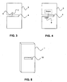
- a coaxial feed can e.g. be used for feeding the slot antenna, which is illustrated in Fig. 3 , wherein grounding 7 of the coaxial feed is provided on one side of the slot 4 and feed 6 is provided on another side of the slot 4 essentially opposite the grounding 7.
- a micro strip feed 8 can also be used for feeding the slot antenna, which is illustrated in Fig. 4 , wherein the micro strip feed further has a stub matching for tuning of the radio frequencies.
- Other possible feedings are e.g. planar feeding and feeding with lumped components.
- the walls of the slot 4 are preferably provided as metal walls connected to the metal cover 1, but could also be provided as open walls, however open wall has the effect that coupling to box cavity modes of the metal cover will be very difficult to control.
- a second embodiment of the present invention will next be described with reference to Fig. 5 .
- This second embodiment of the present invention is similar to the first embodiment described above apart from that the slot 10 is not open ended.
- a drawback with a closed slot 10 compared to an open ended slot according to the first embodiment described above is that it is more difficult to provide lower frequencies for the closed slot antenna 10.
- An advantage is that wiring in the portable radio communication device is easier to provide with the closed slot antenna 10.
- a through non-conductive hole is meant a hole completely through the metal cover, possibly filled with non-conductive materials but no conductive parts leading into or past the slot-shaped hole, apart from feeding.
Landscapes
- Engineering & Computer Science (AREA)
- Computer Networks & Wireless Communication (AREA)
- Support Of Aerials (AREA)
- Waveguide Aerials (AREA)
- Telephone Set Structure (AREA)
- Details Of Aerials (AREA)
Claims (10)
- Couvercle métallique (1) pour un dispositif de communication radio, ledit couvercle métallique (1) comprenant un trou traversant non conducteur formant une fente (4 ; 10) à travers ledit couvercle métallique (1), et une alimentation de fréquences radio (6, 7 ; 8, 9), dans lequel ladite alimentation de fréquences radio (6, 7 ; 8, 9) est placée à travers ladite fente (4 ; 10) pour alimenter ladite fente (4 ; 10) en tant qu'antenne à fente pour ledit dispositif de communication radio, et dans lequel ledit couvercle métallique présente une longueur allongée et caractérisé en ce que ladite fente est orientée latéralement à la longueur du couvercle métallique et essentiellement au milieu de la longueur allongée du couvercle métallique.
- Couvercle métallique selon la revendication 1, dans lequel ladite fente (4) est une fente à extrémité ouverte.
- Couvercle métallique selon la revendication 1 ou 2, dans lequel ladite fente (4) est placée au milieu dudit couvercle métallique (1).
- Couvercle métallique selon la revendication 1 ou 2, dans lequel ladite fente (4) est placée décalée par rapport au milieu dudit couvercle métallique (1).
- Couvercle métallique selon l'une quelconque des revendications 1 à 4, dans lequel ladite alimentation de fréquences radio (6, 7 ; 8, 9) est fournie comme l'une des suivantes : alimentation coaxiale, alimentation microbande, alimentation planaire, et alimentation à composants localisés.
- Couvercle métallique selon l'une quelconque des revendications 1 à 5, dans lequel ladite fente (4 ; 10) présente des parois métalliques.
- Couvercle métallique selon l'une quelconque des revendications 1 à 6, dans lequel ledit couvercle métallique a la forme d'une boîte.
- Couvercle métallique selon l'une quelconque des revendications 1 à 7, dans lequel ladite antenne à fente est conçue pour couvrir les réseaux GSM850, GSM900, GSM1800, GSM1900, UMTS 2100 MHz et WLAN 2,4 GHz.
- Couvercle métallique selon l'une quelconque des revendications 1 à 8, dans lequel ledit dispositif de communication radio est portable.
- Dispositif de communication radio comprenant le couvercle métallique (1) selon la revendication 1.
Priority Applications (6)
| Application Number | Priority Date | Filing Date | Title |
|---|---|---|---|
| DE602006015290T DE602006015290D1 (de) | 2006-05-19 | 2006-05-19 | Metallgehäuse mit schlitzantennen für Funk-Kommunikationsgerät |
| EP06445026A EP1858112B1 (fr) | 2006-05-19 | 2006-05-19 | Boîtier métallique à antenne à fente pour dispositif de communication radio |
| CN2007800018361A CN101366147B (zh) | 2006-05-19 | 2007-05-16 | 用于无线电通信设备的金属壳 |
| PCT/SE2007/000479 WO2007136321A1 (fr) | 2006-05-19 | 2007-05-16 | Couvercle métallique destiné à un dispositif de radiocommunication |
| US12/159,346 US20090153416A1 (en) | 2006-05-19 | 2007-05-16 | Metal cover for a radio communication device |
| KR1020087015354A KR20090013159A (ko) | 2006-05-19 | 2007-05-16 | 무선통신 장치용 금속커버 |
Applications Claiming Priority (1)
| Application Number | Priority Date | Filing Date | Title |
|---|---|---|---|
| EP06445026A EP1858112B1 (fr) | 2006-05-19 | 2006-05-19 | Boîtier métallique à antenne à fente pour dispositif de communication radio |
Publications (2)
| Publication Number | Publication Date |
|---|---|
| EP1858112A1 EP1858112A1 (fr) | 2007-11-21 |
| EP1858112B1 true EP1858112B1 (fr) | 2010-07-07 |
Family
ID=37103255
Family Applications (1)
| Application Number | Title | Priority Date | Filing Date |
|---|---|---|---|
| EP06445026A Not-in-force EP1858112B1 (fr) | 2006-05-19 | 2006-05-19 | Boîtier métallique à antenne à fente pour dispositif de communication radio |
Country Status (6)
| Country | Link |
|---|---|
| US (1) | US20090153416A1 (fr) |
| EP (1) | EP1858112B1 (fr) |
| KR (1) | KR20090013159A (fr) |
| CN (1) | CN101366147B (fr) |
| DE (1) | DE602006015290D1 (fr) |
| WO (1) | WO2007136321A1 (fr) |
Cited By (2)
| Publication number | Priority date | Publication date | Assignee | Title |
|---|---|---|---|---|
| WO2012107835A2 (fr) | 2011-02-11 | 2012-08-16 | Pulse Finland Oy | Dispositif d'antenne à excitation par le châssis et procédés associés |
| EP2562870A1 (fr) | 2011-07-25 | 2013-02-27 | Pulse Finland Oy | Appareil d'antenne en boucle à fente multibande et procédés |
Families Citing this family (28)
| Publication number | Priority date | Publication date | Assignee | Title |
|---|---|---|---|---|
| KR101283070B1 (ko) * | 2007-04-10 | 2013-07-05 | 노키아 코포레이션 | 안테나 배치구성물 및 안테나 하우징 |
| KR101156881B1 (ko) * | 2007-11-28 | 2012-06-20 | 후지쯔 가부시끼가이샤 | 무선 태그에 의해 관리되는 금속 파이프 및 그 무선 태그 |
| US8299971B2 (en) | 2009-03-25 | 2012-10-30 | GM Global Technology Operations LLC | Control module chassis-integrated slot antenna |
| US9774072B2 (en) | 2009-10-09 | 2017-09-26 | Htc Corporation | Housing, handheld device, and manufacturing method of housing |
| CN102576928A (zh) * | 2009-10-29 | 2012-07-11 | 莱尔德技术股份有限公司 | 用于无线电通信装置的金属盖 |
| US8711044B2 (en) | 2009-11-12 | 2014-04-29 | Nokia Corporation | Antenna arrangement and antenna housing |
| EP2355242A1 (fr) * | 2010-02-02 | 2011-08-10 | Laird Technologies AB | Dispositif d'antenne pour dispositif de communication radio |
| EP2355241A1 (fr) * | 2010-02-02 | 2011-08-10 | Laird Technologies AB | Dispositif d'antenne pour dispositif de communication radio |
| EP2387100B1 (fr) * | 2010-04-29 | 2012-12-05 | Laird Technologies AB | Couvercle métallique pour dispositif de communication radio |
| EP2469645B1 (fr) * | 2010-12-22 | 2013-05-15 | Laird Technologies AB | Arrangement d'antenne pour dispositif de communication radio portable doté d'un boîtier métallique |
| US8638265B2 (en) * | 2011-03-11 | 2014-01-28 | Microsoft Corporation | Slot antenna |
| CN103531905A (zh) * | 2012-07-06 | 2014-01-22 | 宏碁股份有限公司 | 电子装置 |
| US8884835B2 (en) * | 2012-08-09 | 2014-11-11 | Intel Mobile Communications GmbH | Antenna system, method and mobile communication device |
| US9716307B2 (en) | 2012-11-08 | 2017-07-25 | Htc Corporation | Mobile device and antenna structure |
| US9655261B2 (en) | 2013-03-21 | 2017-05-16 | Htc Corporation | Casing of electronic device and method of manufacturing the same |
| KR102117518B1 (ko) * | 2013-07-09 | 2020-06-01 | 엘지전자 주식회사 | 이동 단말기 |
| EP2854214A1 (fr) | 2013-09-27 | 2015-04-01 | Thomson Licensing | Ensemble d'antenne pour dispositif électronique |
| US9608310B2 (en) | 2014-05-23 | 2017-03-28 | Nokia Technologies Oy | Apparatus having a conductive housing and an antenna with tunable resonance |
| CN105522280B (zh) * | 2014-12-26 | 2017-06-06 | 比亚迪股份有限公司 | 一种通讯设备金属外壳的制备方法 |
| CN105098330B (zh) * | 2015-08-04 | 2018-08-21 | 青岛海信移动通信技术股份有限公司 | 移动终端天线和移动终端 |
| WO2017052159A1 (fr) * | 2015-09-22 | 2017-03-30 | 주식회사 맵스 | Boîtier métallique capable de transmission d'énergie sans fil pour dispositif électronique |
| US9917347B2 (en) | 2015-10-27 | 2018-03-13 | Dell Products L.P. | Hinge barrel antenna system |
| CN105573111A (zh) * | 2016-02-17 | 2016-05-11 | 广东小天才科技有限公司 | 智能穿戴设备 |
| TWI619305B (zh) * | 2016-02-19 | 2018-03-21 | 群邁通訊股份有限公司 | 天線結構及具有該天線結構之無線通訊裝置 |
| CN106299662A (zh) * | 2016-09-20 | 2017-01-04 | 惠州硕贝德无线科技股份有限公司 | 新型缝隙天线 |
| CN107872936B (zh) * | 2016-09-28 | 2020-10-23 | 华为机器有限公司 | 一种移动设备的金属壳及其制备方法、移动设备 |
| CN111430921B (zh) * | 2020-03-31 | 2024-03-01 | 北京小米移动软件有限公司 | 超宽带天线及通信终端 |
| US11264724B2 (en) * | 2020-07-20 | 2022-03-01 | TE Connectivity Services Gmbh | Omnidirectional antenna assembly |
Family Cites Families (11)
| Publication number | Priority date | Publication date | Assignee | Title |
|---|---|---|---|---|
| US4410890A (en) * | 1981-05-06 | 1983-10-18 | The United States Of America As Represented By The Field Operations Bureau Of The Fcc | VHF Directional receiver |
| JPS6234404A (ja) * | 1985-08-07 | 1987-02-14 | Fujitsu Ltd | 無線機用アンテナ |
| US4723305A (en) * | 1986-01-03 | 1988-02-02 | Motorola, Inc. | Dual band notch antenna for portable radiotelephones |
| KR920002439B1 (ko) * | 1988-08-31 | 1992-03-24 | 삼성전자 주식회사 | 휴대용 무선전화기의 슬로트 안테나 장치 |
| EP0851530A3 (fr) * | 1996-12-28 | 2000-07-26 | Lucent Technologies Inc. | Antenne dans terminaux sans fils |
| US6282433B1 (en) * | 1999-04-14 | 2001-08-28 | Ericsson Inc. | Personal communication terminal with a slot antenna |
| US6424300B1 (en) * | 2000-10-27 | 2002-07-23 | Telefonaktiebolaget L.M. Ericsson | Notch antennas and wireless communicators incorporating same |
| US6618020B2 (en) * | 2001-12-18 | 2003-09-09 | Nokia Corporation | Monopole slot antenna |
| US6879293B2 (en) * | 2002-02-25 | 2005-04-12 | Tdk Corporation | Antenna device and electric appliance using the same |
| US20040257283A1 (en) * | 2003-06-19 | 2004-12-23 | International Business Machines Corporation | Antennas integrated with metallic display covers of computing devices |
| JP2005086531A (ja) * | 2003-09-09 | 2005-03-31 | Sony Corp | 無線通信装置 |
-
2006
- 2006-05-19 EP EP06445026A patent/EP1858112B1/fr not_active Not-in-force
- 2006-05-19 DE DE602006015290T patent/DE602006015290D1/de active Active
-
2007
- 2007-05-16 KR KR1020087015354A patent/KR20090013159A/ko not_active Withdrawn
- 2007-05-16 CN CN2007800018361A patent/CN101366147B/zh not_active Expired - Fee Related
- 2007-05-16 WO PCT/SE2007/000479 patent/WO2007136321A1/fr not_active Ceased
- 2007-05-16 US US12/159,346 patent/US20090153416A1/en not_active Abandoned
Cited By (2)
| Publication number | Priority date | Publication date | Assignee | Title |
|---|---|---|---|---|
| WO2012107835A2 (fr) | 2011-02-11 | 2012-08-16 | Pulse Finland Oy | Dispositif d'antenne à excitation par le châssis et procédés associés |
| EP2562870A1 (fr) | 2011-07-25 | 2013-02-27 | Pulse Finland Oy | Appareil d'antenne en boucle à fente multibande et procédés |
Also Published As
| Publication number | Publication date |
|---|---|
| KR20090013159A (ko) | 2009-02-04 |
| EP1858112A1 (fr) | 2007-11-21 |
| CN101366147B (zh) | 2012-10-03 |
| US20090153416A1 (en) | 2009-06-18 |
| WO2007136321A1 (fr) | 2007-11-29 |
| DE602006015290D1 (de) | 2010-08-19 |
| CN101366147A (zh) | 2009-02-11 |
Similar Documents
| Publication | Publication Date | Title |
|---|---|---|
| EP1858112B1 (fr) | Boîtier métallique à antenne à fente pour dispositif de communication radio | |
| US10833398B2 (en) | Mobile device and antenna structure | |
| EP2704252B1 (fr) | Structure d'antenne et dispositif mobile | |
| TWI514666B (zh) | 行動裝置 | |
| TWI523312B (zh) | 行動裝置 | |
| EP3010081B1 (fr) | Dispositif mobile | |
| TWI599095B (zh) | 天線結構及應用該天線結構的無線通訊裝置 | |
| CN103682583B (zh) | 移动装置 | |
| JP2013005431A (ja) | 携帯端末機のアンテナ装置 | |
| GB2523367A (en) | An apparatus for wireless communication | |
| CN110854509B (zh) | 用于无线通信的装置 | |
| EP2387100B1 (fr) | Couvercle métallique pour dispositif de communication radio | |
| WO2006073180A1 (fr) | Peripherique radio portable | |
| WO2011050845A1 (fr) | Couvercle métallique de dispositif de radiocommunication | |
| EP2725767B1 (fr) | Dispositif électronique sans fil avec un périmètre métallique comportant un composant plan d'entrée utilisateur | |
| US20120162027A1 (en) | Antenna Arrangement For A Portable Radio Communication Device | |
| US20120293378A1 (en) | Antenna arrangement for a portable radio communication device having a metal casing | |
| Lee et al. | Frequency reconfigurable antenna using a PIN diode for mobile handset application | |
| CN103682581B (zh) | 移动装置 | |
| Huang et al. | A small size three-band multi-functional antenna for LTE/GSM/UMTS/WIMAX handsets | |
| KR20050110491A (ko) | 안테나를 결합한 외장형 메모리 장치 |
Legal Events
| Date | Code | Title | Description |
|---|---|---|---|
| PUAI | Public reference made under article 153(3) epc to a published international application that has entered the european phase |
Free format text: ORIGINAL CODE: 0009012 |
|
| AK | Designated contracting states |
Kind code of ref document: A1 Designated state(s): AT BE BG CH CY CZ DE DK EE ES FI FR GB GR HU IE IS IT LI LT LU LV MC NL PL PT RO SE SI SK TR |
|
| AX | Request for extension of the european patent |
Extension state: AL BA HR MK YU |
|
| 17P | Request for examination filed |
Effective date: 20080519 |
|
| 17Q | First examination report despatched |
Effective date: 20080623 |
|
| AKX | Designation fees paid |
Designated state(s): DE FI FR |
|
| GRAP | Despatch of communication of intention to grant a patent |
Free format text: ORIGINAL CODE: EPIDOSNIGR1 |
|
| RIN1 | Information on inventor provided before grant (corrected) |
Inventor name: KAIKKONEN, ANDREI Inventor name: PASALIC, ERMIN Inventor name: LINDBERG, PETER Inventor name: VON ARBIN, AXEL |
|
| GRAS | Grant fee paid |
Free format text: ORIGINAL CODE: EPIDOSNIGR3 |
|
| GRAA | (expected) grant |
Free format text: ORIGINAL CODE: 0009210 |
|
| AK | Designated contracting states |
Kind code of ref document: B1 Designated state(s): DE FI FR |
|
| REF | Corresponds to: |
Ref document number: 602006015290 Country of ref document: DE Date of ref document: 20100819 Kind code of ref document: P |
|
| PG25 | Lapsed in a contracting state [announced via postgrant information from national office to epo] |
Ref country code: FI Free format text: LAPSE BECAUSE OF FAILURE TO SUBMIT A TRANSLATION OF THE DESCRIPTION OR TO PAY THE FEE WITHIN THE PRESCRIBED TIME-LIMIT Effective date: 20100707 |
|
| PLBE | No opposition filed within time limit |
Free format text: ORIGINAL CODE: 0009261 |
|
| STAA | Information on the status of an ep patent application or granted ep patent |
Free format text: STATUS: NO OPPOSITION FILED WITHIN TIME LIMIT |
|
| 26N | No opposition filed |
Effective date: 20110408 |
|
| REG | Reference to a national code |
Ref country code: DE Ref legal event code: R097 Ref document number: 602006015290 Country of ref document: DE Effective date: 20110408 |
|
| REG | Reference to a national code |
Ref country code: FR Ref legal event code: ST Effective date: 20120131 |
|
| PG25 | Lapsed in a contracting state [announced via postgrant information from national office to epo] |
Ref country code: FR Free format text: LAPSE BECAUSE OF NON-PAYMENT OF DUE FEES Effective date: 20110531 |
|
| PGFP | Annual fee paid to national office [announced via postgrant information from national office to epo] |
Ref country code: DE Payment date: 20130527 Year of fee payment: 8 |
|
| REG | Reference to a national code |
Ref country code: DE Ref legal event code: R119 Ref document number: 602006015290 Country of ref document: DE |
|
| REG | Reference to a national code |
Ref country code: DE Ref legal event code: R119 Ref document number: 602006015290 Country of ref document: DE Effective date: 20141202 |
|
| PG25 | Lapsed in a contracting state [announced via postgrant information from national office to epo] |
Ref country code: DE Free format text: LAPSE BECAUSE OF NON-PAYMENT OF DUE FEES Effective date: 20141202 |