EP1858130A2 - Collier de montage - Google Patents
Collier de montage Download PDFInfo
- Publication number
- EP1858130A2 EP1858130A2 EP07108495A EP07108495A EP1858130A2 EP 1858130 A2 EP1858130 A2 EP 1858130A2 EP 07108495 A EP07108495 A EP 07108495A EP 07108495 A EP07108495 A EP 07108495A EP 1858130 A2 EP1858130 A2 EP 1858130A2
- Authority
- EP
- European Patent Office
- Prior art keywords
- mounting hole
- engaging
- column
- lateral wall
- clamp
- Prior art date
- Legal status (The legal status is an assumption and is not a legal conclusion. Google has not performed a legal analysis and makes no representation as to the accuracy of the status listed.)
- Withdrawn
Links
Images







Classifications
-
- H—ELECTRICITY
- H02—GENERATION; CONVERSION OR DISTRIBUTION OF ELECTRIC POWER
- H02G—INSTALLATION OF ELECTRIC CABLES OR LINES, OR OF COMBINED OPTICAL AND ELECTRIC CABLES OR LINES
- H02G3/00—Installations of electric cables or lines or protective tubing therefor in or on buildings, equivalent structures or vehicles
- H02G3/30—Installations of cables or lines on walls, floors or ceilings
- H02G3/32—Installations of cables or lines on walls, floors or ceilings using mounting clamps
-
- B—PERFORMING OPERATIONS; TRANSPORTING
- B60—VEHICLES IN GENERAL
- B60R—VEHICLES, VEHICLE FITTINGS, OR VEHICLE PARTS, NOT OTHERWISE PROVIDED FOR
- B60R16/00—Electric or fluid circuits specially adapted for vehicles and not otherwise provided for; Arrangement of elements of electric or fluid circuits specially adapted for vehicles and not otherwise provided for
- B60R16/02—Electric or fluid circuits specially adapted for vehicles and not otherwise provided for; Arrangement of elements of electric or fluid circuits specially adapted for vehicles and not otherwise provided for electric constitutive elements
- B60R16/0207—Wire harnesses
- B60R16/0215—Protecting, fastening and routing means therefor
-
- F—MECHANICAL ENGINEERING; LIGHTING; HEATING; WEAPONS; BLASTING
- F16—ENGINEERING ELEMENTS AND UNITS; GENERAL MEASURES FOR PRODUCING AND MAINTAINING EFFECTIVE FUNCTIONING OF MACHINES OR INSTALLATIONS; THERMAL INSULATION IN GENERAL
- F16B—DEVICES FOR FASTENING OR SECURING CONSTRUCTIONAL ELEMENTS OR MACHINE PARTS TOGETHER, e.g. NAILS, BOLTS, CIRCLIPS, CLAMPS, CLIPS OR WEDGES; JOINTS OR JOINTING
- F16B21/00—Means for preventing relative axial movement of a pin, spigot, shaft or the like and a member surrounding it; Stud-and-socket releasable fastenings
- F16B21/06—Releasable fastening devices with snap-action
- F16B21/08—Releasable fastening devices with snap-action in which the stud, pin, or spigot has a resilient part
- F16B21/086—Releasable fastening devices with snap-action in which the stud, pin, or spigot has a resilient part the shank of the stud, pin or spigot having elevations, ribs, fins or prongs intended for deformation or tilting predominantly in a direction perpendicular to the direction of insertion
-
- F—MECHANICAL ENGINEERING; LIGHTING; HEATING; WEAPONS; BLASTING
- F16—ENGINEERING ELEMENTS AND UNITS; GENERAL MEASURES FOR PRODUCING AND MAINTAINING EFFECTIVE FUNCTIONING OF MACHINES OR INSTALLATIONS; THERMAL INSULATION IN GENERAL
- F16L—PIPES; JOINTS OR FITTINGS FOR PIPES; SUPPORTS FOR PIPES, CABLES OR PROTECTIVE TUBING; MEANS FOR THERMAL INSULATION IN GENERAL
- F16L3/00—Supports for pipes, cables or protective tubing, e.g. hangers, holders, clamps, cleats, clips, brackets
- F16L3/22—Supports for pipes, cables or protective tubing, e.g. hangers, holders, clamps, cleats, clips, brackets specially adapted for supporting a number of parallel pipes at intervals
- F16L3/23—Supports for pipes, cables or protective tubing, e.g. hangers, holders, clamps, cleats, clips, brackets specially adapted for supporting a number of parallel pipes at intervals for a bundle of pipes or a plurality of pipes placed side by side in contact with each other
- F16L3/233—Supports for pipes, cables or protective tubing, e.g. hangers, holders, clamps, cleats, clips, brackets specially adapted for supporting a number of parallel pipes at intervals for a bundle of pipes or a plurality of pipes placed side by side in contact with each other by means of a flexible band
- F16L3/2336—Supports for pipes, cables or protective tubing, e.g. hangers, holders, clamps, cleats, clips, brackets specially adapted for supporting a number of parallel pipes at intervals for a bundle of pipes or a plurality of pipes placed side by side in contact with each other by means of a flexible band having two or more locking barbs
Definitions
- the present invention relates to a part mounting clamp used for attaching a wire harness or a part such as a band for tying wire harness to an attaching subject such as a metal panel of an automobile body.
- a part mounting clamp includes a support portion which covers a peripheral portion of a mounting hole formed in an attaching subject in a state where the support portion has a part mounting portion, a column which projects from the support portion and is inserted into the mounting hole, and a pair of engaging pieces which extend toward the support portion in a state where the engaging pieces are supported respectively by both sides of a lower end of the column in a cantilever manner, and also, on outer sides of an upper end of which engaging steps are formed, wherein the engaging steps can engage with a peripheral portion of the mounting hole.
- the pair of engaging pieces When the column is inserted into themountinghole, the pair of engaging pieces are resiliently rocked and deformed inward by slide contact with an inner periphery of the mounting hole, and the engaging step is engaged with the peripheral portion of the mounting hole of the attaching subject, thereby obtaining an attached state wherein the pair of engaging pieces and the support portion sandwich the attaching subject.
- a part mounting portion of a support portion is a holding portion (reference number 3) of cables.
- the part mounting clamp includes a support portion (reference number 11) having a pair of left and right resiliently supporting pieces (reference number 67), and a pair of engaging pieces (reference number 63) which are supported respectively by left and right sides of a lower end of a column (reference number 61) in a cantilever manner.
- a peripheral portion of a mounting hole is engaged with an engaging step (reference number 65) by inserting operation into the mounting hole of an attaching subject such as a metal plate (not shown).
- apartmountingportion of a support portion is a band (reference number 1) for tying wire harness.
- the part mounting clamp includes a support portion (reference number 3) having a pair of left and right pressing pieces (reference number 7), and a pair of engaging pieces (reference number 6b) supported respectively on left and right sides of a lower end of a column (reference number 6) in a cantilever manner. As shown in Fig.
- a peripheral portion (reference number 4a) of a mounting hole (reference number 4) is engaged with an engaging step (reference number 6d) by inserting operation of an attaching subject (no reference number) such as a metal plate into the mounting hole.
- the pair of engaging pieces are resiliently deformed inward as the column is inserted into the mounting hole, the engaging pieces pass through the mounting hole, and the engaging step is automatically engaged with the peripheral portion of the mounting hole by the outward resilience of the engaging piece.
- the engaging step of the part mounting clamp includes a vertical wall extending along an inner peripheral surface of the mounting hole, and a lateral wall extending along an outer surface of a peripheral portion of the mounting hole. In a mounting state on the mounting hole, a contained angle between the vertical wall and the lateral wall is set to 90° so that it comes in contact with both an inner peripheral surface of the mounting hole and an outer surface of the peripheral portion so as to be stably clamped.
- a flaggy portion is generated on an edge of the mounting hole on the press punch entering side
- a burr is generated on the opposite side in many cases. That is, as shown in Fig. 11, a flaggy portion d is a phenomenon in which an edge of a mounting hole 3 is plastically deformed in an angle round form, and a burr b is a phenomenon in which a fine metal piece (metal wall) projects.
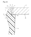
- a burr b is formed on a lower edge of the mounting hole 3, even when the tip end of the lateral wall 9y assumes a position where the tip end can slide in (position where the tip end of the lateral wall 9y is located on a phantom line which is a set plate thickness in Fig. 11), it is hindered by the burr b and it can not smoothly rock and move such as to spread laterally in a direction of arrow A by the resilience of the engaging piece 8. Therefore, there is inconvenience that it collides with the burr b and can not be engaged, or as shown in Fig. 12, since the tip end of the burr b is sharply pointed, the lateral wall 9y is caught in a tip end of the burr b and engaged improperly, and engaged length is short to be easily disengaged.
- the support portion when the material is synthetic resin or the like, the support portion can be resiliently deformed in the vertical direction to some extent, thereby it is possible to forcibly engage the engaging step 9 with the mounting hole 3 by strongly inserting the engaging step 9 and wrapping the lateral wall 9y below the burr b.
- this operation is slightly deviated from a normal inserting operation of intentionally pushing strongly (operation that requires an unpredictable strong force.
- the above-described engagement failure often occurs due to insufficient inserting force or the like.
- the present invention provides a part mounting clamp comprising a column 7 inserted into a mounting hole 3 formed in an attaching subject 2, a support portion 6 which is spread sideway from an outer peripheral portion of an upper end of the column 7 and which covers a peripheral portion 2a of the mounting hole 3, a part mounting portion 5 mounted on the support portion 6 or the column 7, a pair of engaging pieces 8 and 8 which are extend toward the support portion 6 in a state of being supported respectively on both sides of a tip end of the column 7 in a cantilever manner, and which include tip ends capable of engaging with the peripheral portion 2a of the mounting hole 3, and engaging steps 9 establishing an attached state in which the pair of engaging pieces 8 and 8 come into slide contact with an inner periphery of the mounting hole 3 by inserting the column 7 into the mounting hole 3, thereby resiliently rocking and deforming the engaging pieces 8 and 8 inward and the attaching subject 2 is sandwiched between the pair of engaging pieces 8 and 8 and the support portion 6, each of the engaging steps 9 including a vertical wall 9t abutting against an inner
- an improved partmounting clamp in which even when an angle edge of the mounting hole on the side where the engaging step is engaged is formed with a burr by the press forming or the like, the engaging step is engaged with the mounting hole and is moved in the predetermined manner by the resilience of the pair of engaging pieces which are forcibly resiliently deformed inwardly so as to pass through the mounting hole together with the inserting operation of the column into the mounting hole, a reliable engaged state can be obtained, it is possible to sufficiently withstand a force in the pulling out direction, it can be held stably.
- the engaging step can be engaged easily and it is difficult for the engaging step to be pulled out from the mounting hole with excellent balance, in case that there is a burr on the edge of the mounting hole. This shows a high effect that it is easy to mount the engaging step, and a stable attached state can be realized.
- an angle formed between the inner peripheral surface 3n and the outer surface 2A is 90° or about 90°, and the vertical wall 9t and the lateral wall 9y are set such that an angle therebetween is equal to the angle made by adding 90° or about 90° and the contained angle of 5°.
- the angle formed between the inner peripheral surface of the mounting hole and the outer surface of the attaching subject is 90° or about 90°
- the angle formed between the vertical wall and the lateral wall of the engaging step may be set to 90° or about 90° plus 5°.
- the part mounting portion 5 is an insertion hole formed in the column 7, through which a tying band B for tying wire harness W is inserted.
- the part mounting clamp can effectively be used as a harness retaining clamp which ties a wire harness and supports the same on the attaching subject.
- Fig. 1 is a perspective view as a tying fixing tool in which wire harnesses are tied to the part mounting clamp using a tying band.
- Fig. 2 is a sectional view of the tying fixing tool in a direction along a longitudinal direction of the wire harness.
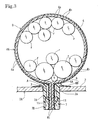
- Fig. 3 is a sectional view of the tying fixing tool in a direction perpendicular to the longitudinal direction of the wire harness.
- Fig. 4 is an enlarged view of an essential portion showing an engaged state between the part mounting clamp and an attaching subject.
- Fig. 5 is a sectional side view of a discrete part mounting clamp. Figs.
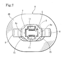
- FIG. 6 and 7 are front, side and bottom views of the part mounting clamp.
- Fig. 8 is an enlarged sectional view showing the engagement starting state of the engaging step with respect to the mounting hole.
- Fig. 9 is an enlarged sectional view showing an attached state of the engaging piece to the mounting hole having a burr.
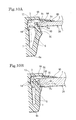
- Fig. 10 is a sectional view of an essential portion showing an engaged state of the engaging piece with respect to a thin panel plate and a thick panel plate.
- Figs. 11 and 12 are sectional views of an essential portion showing conventional engagement functions.
- a part mounting clamp according to a first embodiment is constituted as a tying head A having a clamp in a tying fixing tool 1 for tying a wire harness W and clamping the same on an attaching subject 2 in corporation with a tying band B as shown in Fig. 1. That is; a tying fixing tool 1 comprises the tying head A having the clamp and the tying band B. The tying fixing tool 1 ties the wire harness W to a panel plate 2 constituting an automobile body part that is one example of the attaching subject so that the wire harness W can be retained thereto.
- Figs. 2 and 3 show a state where the wire harness W is tied and retained to the panel plate 2 using the tying fixing tool 1.
- the tying fixing tool 1 comprises two parts, i.e., the tying head A having the clamp retained and fixed to the mounting hole 3 of the panel plate, and the tying band B retained and fixed to the tying head A having the clamp in a state where the wire harness W is surrounded. That is, the wire harness W comprising a large number of electric wires r are surrounded by the tying band B and in this state, the wire harness W is retained and fixed to the tying head A having the clamp, and the tying fixing tool 1 having the wire harness W is retained and fixed to the panel plate 2 by the tying head A having the clamp.
- the tying band B has a band member 4 made of synthetic resin having flexibility such as nylon and polypropylene, and one of front and rear surface of the band member 4 is formed with valleys 4a and mountains 4b. The valleys 4a and the mountains 4b are alternately formed in the recessed manner. Retaining portions 4K are continuously formed.
- a band reel wound around a rotation reel is reeled off and supplied, and the supplied reel is cut into appropriate length and is used as the tying band.
- the tying head A having the clamp includes a support portion 6, a column 7 and a pair of engaging pieces 8 and 8 .
- the support portion 6 covers a peripheral portion of a long circular mounting hole 3 formed in a panel plate 2 (one example of the attaching subject) in a state where the support portion 6 has an insertion hole 5 (one example of the part mounting portion) through which the tying band B is to be inserted.
- the column 7 projects from the support portion 6 and is inserted into the mounting hole 3.
- the engaging pieces 8 and 8 extend toward the support portion 6 in a state of being supported respectively on both sides of a lower tip end of the column 7 in a cantilever manner, and the engaging piece 8 is formed at its outer side of its upper end with an engaging step 9 which can be engaged with a peripheral portion 2a of the mounting hole 3.
- the tying head A having the clamp is made of synthetic resin having flexibility such as nylon and polypropylene. If the column 7 is inserted into the mounting hole 3, the pair of engaging pieces 8 and 8 are resiliently rocked and deformed toward the inside by the sliding motion with respect to the inner peripheral surface 3n (or angle edge) of the mounting hole 3 (see Fig. 4), the engaging step 9 is engaged with the mounting hole peripheral portion 2a of the panel plate 2, and the panel plate 2 is sandwiched between the pair of engaging pieces 8 and 8 and the support portion 6, thereby achieving the attached state.
- the support portion 6 is formed into a long and circular reversed cup-like shape as viewed from above, and this shape corresponds to that of the mounting hole 3.
- the support portion 6 comprises a thick central region 6A which is continuous with the upper end of the column 7, and a skirt portion 6B formed around the column 7.
- the support portion 6 is formed such that it can be resiliently deformed in the vertical direction (inserting direction into the insertion hole 3) so as to urge and sandwich the peripheral portion 2a of the mounting hole 3 between the pair of left and right engaging pieces (one example of the clamp portion) 8 and 8.
- the central region 6A of the support portion 6 is formed thicker than a peripheral portion of the support portion 6.
- the column 7 is a cylindrical portion through which the insertion hole 5 is formed vertically.
- the insertion hole 5 has a substantially rectangular shape as viewed from above (as viewed from below). Both ends 4t and 4t of the band member 4 are inserted into the insertion hole 5 in an opposed state.
- a pair of second engaging pieces 11 and 11 projects downward and inward in the insertion hole 5.
- the second engaging pieces 11 and 11 are engaged with valleys 4a of the ends 4t and 4t.
- the second engaging pieces 11 and 11 are supported in the cantilever manner in a state where they are opposed to each other in the longitudinal direction.
- the second engaging piece 11 is integrally formed such that it is continuous with the thick column portion 7A at a boundary between the upper thick column portion 7A and the lower thin column portion 7B.
- the second engaging piece 11 is formed at its inner side with two engaging mountains 11a and engaging valleys 11b.
- the pair of engaging pieces 8 and 8 are supported in the cantilever manner such that they project diagonally upward from left and right portions of the lower end of the column 7.
- the engaging piece 8 can laterally be rocked and deformed around a root 8a of the lower end, and the outer side of the upper end of the engaging piece 8 is formed with an engaging step 9 comprising first to third steps 9A to 9C.
- Each of the steps 9A to 9C comprises a corner angle portion having vertical wall 9t and a lateral wall 9y.
- the vertical wall 9t is formed into an arc curved surface as viewed from above and this shape corresponds to that of the mounting hole 3.
- a contained angle ⁇ between the vertical wall 9t and the lateral wall 9y is set to 95°.
- each of the steps 9A to 9C includes the vertical wall 9t extending along an inner peripheral surface 3n of the mounting hole 3 of the panel plate 2 and the lateral wall 9y extending along the outer surface (lower surface) of the peripheral portion 2a of the mounting hole 3 of the panel plate 2.
- the engaging step 9 is formed such that a slight gap contained angle ⁇ exists between the lateral wall 9y and the outer surface 2A.
- the contained angle ⁇ is set to 5°.
- the contained angle ⁇ formed between the vertical wall 9t and the lateral wall 9y is set to 95°.
- the angle formed between the inner peripheral surface 3n of the mounting hole 3 and the lower outer surface 2A of the panel plate 2 is right-angled (90° or substantially 90°) .
- a contained angle (angle) formed between the vertical wall 9t and the lateral wall 9y is set to a value (95°) obtained by adding the gap contained angle ⁇ to a right angle (90° or substantially 90°).
- the first to third steps 9A to 9C are properly used depending upon the thickness of the panel plate 2.
- the mounting hole 3 is engaged with the first step 9A
- the panel plate 2 is thick, as shown in Fig. 10 (b)
- the mounting hole 3 is engaged with the third step 9C.
- the panel plate 2 has standard thickness (intermediate thickness), as shown in Figs. 4 and 9, the mounting hole 3 is engaged with the second step 9B. With any thickness, the size of the mounting hole 3 is the same, and selection of the first to third steps 9A to 9C is adjusted depending upon the magnitude of the rocking deformation of the engaging piece 8 .
- the engaging piece 8 and the engaging step 9 are formed such that the gap contained angle ⁇ becomes 5° irrespective of the thickness.
- the mounting hole 3 of the panel plate 2 made of sheet metal is usually integrally formed by press forming.
- a peripheral edge of the mounting hole 3 on the press punch entering side is formed with "flaggy portion” which is subjected to angle R processing in many cases, and the peripheral edge of the mounting hole 3 on the press punch discharging side with "burr".
- a flaggy portion d is formed on an upper angle portion which is the inserting side of the tying head A having the clamp, and a burr b is formed on a lower angle portion which is a catching side of the engaging piece 8. This case will be explained below.
- the lateral wall 9y of the second step 9B and the lower outer surface 2A of the panel plate 2 are substantially in parallel to each other or form a slight opening angle (such an angle that the lateral wall 9y inclined downward and rightward with respect to the outer surface 2A in Fig. 8) in a state where the angle portion k comes to a lower end of the burr b. Therefore, the burr b and the lateral wall 9y easily slide and move with respect to each other by the resilience of the engaging piece 8, and such behavior that the second step 9B is engaged with the mounting hole 3 relatively smoothly is provided (see Fig. 9).
- the lateral wall 9y and the vertical wall 9t of the second step 9B are set to a right angle (90°). Therefore, if the moving state of the engaging piece 8 is the same as that of the present invention, it can be understood that the vertical height of the burr b can not still move laterally.
- the engaging piece 8 is designed such that in a normal engaging state, the inner peripheral surface 3n of the mounting hole 3 and the vertical wall 9t are in parallel to each other and can be excellently abutted against each other, and for this end, in a state immediately before engagement (shown in Fig. 8), the lateral wall 9y and the lower outer surface 2A form a contained angle (such an angle that the lateral wall 9y inclined upward and rightward with respect to the outer surface 2A in Fig. 8).
- the vertical wall 9t and the inner peripheral surface 3n of the mounting hole 3 are abutted against each other in a surface-surface contact manner as shown in Fig. 9, and they are engaged with each other in a state where the burr b is located on the side of a root of the lateral wall 9y (on the side of the vertical wall 9t). That is, a case in which the burr b is caught in the lateral wall 9y and stopped halfway and the burr is not completely engaged can be avoided, and it is possible to obtain excellent engagement state where the vertical wall 9t abuts against the inner peripheral surface 3n of the mounting hole 3.
- the engaging step 9 is formed such that the mounting hole 3 is engaged with the first step 9A and the gap contained angle ⁇ between the lower outer surface 2A of the panel plate 2 and the lateral wall 9y of the first step 9A becomes 5 to 6°.
- the engaging step 9 is formed such that the mounting hole 3 is engaged with the third step 9C and the gap contained angle ⁇ between the lower outer surface 2A of the panel plate 2 and the lateral wall 9y of the third step 9C becomes 5 to 6°.
- a value of the contained angle (contained angle ⁇ between two sides) will be considered. It is preferable that the gap contained angle ⁇ is large to some extent in view of easiness of engagement movement of the engaging step 9 to the mounting hole peripheral portion 2a caused when the column 7 is inserted into the mounting hole 3. However, if the gap contained angle ⁇ becomes large, component of force for rocking the engaging piece 8 inward by the gap contained angle ⁇ is generated when the tensile force in a direction pulling out the wire harness W or the tying head A having the clamp is applied, and there is a problem that the engaging piece 8 is prone to be pulled out from the mounting hole 3. Thus, it is not preferable to increase the gap contained angle ⁇ so much. Therefore, it can be said that it is preferable that the gap contained angle ⁇ is as small as possible for stably holding as a clamp in a range where the engaging step 9 can be engaged with the mounting hole 3 even if the burr b is generated.
- the height (projecting amount) of the burr b when a mounting hole 3 having general size (about 10mm) was formed on the panel plate 2 having standard thickness (about 1mm) by the press forming was checked, and it was found that the height was about 0.2 to 0.3mm (average value) .
- the gap contained angle ⁇ calculated from various conditions such as the height of the burr b and the length of the lateral wall 9y is set to within a range of 4 to 10°, it is possible to satisfy the two elements, i.e., the "easiness of engagement” and "sufficient pulling out proof stress” to some degrees. If the range of the gap contained angle ⁇ is set to 5°, the easiness of engagement between the engaging step 9 and the mounting hole peripheral portion 2a and the pulling out difficulty from the mounting hole 3 can be balanced excellently (easy to engage but difficult to pull out). That is, the optimal value of ⁇ is 5°.
- recessed portions 13 for facilitating the inward resilient deformation of the engaging piece 8 are formed in upper portions of the left and right side walls 12 and 12 of the column 7. That is, as the column 7 is inserted into the insertion hole 3, the left and right engaging pieces 8 and 8 come slid contact with the inner peripheral surface 3n and resiliently deform inward, but in a state where the engaging pieces 8 and 8 are deformed most inward to pass through the insertion hole 3 (shown with phantom line in Fig. 4), the tip end inner portion 14 enters the recessed portion 13.
- the tip end inner portion 14 temporarily enters inward more than the outlines of the left and right side walls 12 of the column 7 so that the movable range of rocking movement of the engaging piece 8 is increased inward.
- this function is likewise exhibited even when the panel plate 2 is thin (see Fig. 10(a)) and when the panel plate 2 is thick (Fig. 10 (b)) .
- Fig. 10 (a) the panel plate 2 is thin
- Fig. 10 (b) Fig. 10 (b)
- reinforcing walls 15 which project laterally in a form of a triangle are integrally formed on a front or rear portions of the recessed portions 13 in the upper portions of left and right side walls 12 of the column 7, and the column 7 and the support portion 6 are integrally formed with sufficient strength.
- the part mounting clamp A it is possible to use not only the tying head having the clamp, but also various members such as a tying band having a clamp in which a base portion of the tying band is integrally formed on the tying head having the clamp, and a support metal tool mounting clamp having a nut for bolting a holding metal tool of a high pressure electric wire. It is possible to variably change the attaching subject to a plate forming a body of a vehicle, agricultural machinery, constructionmachinery and the like, and a frame of the industrial machinery.
Landscapes
- Engineering & Computer Science (AREA)
- General Engineering & Computer Science (AREA)
- Mechanical Engineering (AREA)
- Architecture (AREA)
- Civil Engineering (AREA)
- Structural Engineering (AREA)
- Insertion Pins And Rivets (AREA)
- Connection Of Plates (AREA)
Applications Claiming Priority (1)
| Application Number | Priority Date | Filing Date | Title |
|---|---|---|---|
| US11/435,884 US20070272807A1 (en) | 2006-05-18 | 2006-05-18 | Part mounting clamp |
Publications (2)
| Publication Number | Publication Date |
|---|---|
| EP1858130A2 true EP1858130A2 (fr) | 2007-11-21 |
| EP1858130A3 EP1858130A3 (fr) | 2013-04-17 |
Family
ID=38323759
Family Applications (1)
| Application Number | Title | Priority Date | Filing Date |
|---|---|---|---|
| EP07108495.8A Withdrawn EP1858130A3 (fr) | 2006-05-18 | 2007-05-18 | Collier de montage |
Country Status (2)
| Country | Link |
|---|---|
| US (1) | US20070272807A1 (fr) |
| EP (1) | EP1858130A3 (fr) |
Cited By (4)
| Publication number | Priority date | Publication date | Assignee | Title |
|---|---|---|---|---|
| FR3016937A1 (fr) * | 2014-01-24 | 2015-07-31 | Trw Automotive Electron & Comp | Clip de montage |
| CN105322473A (zh) * | 2014-05-30 | 2016-02-10 | 住友电装株式会社 | 线束夹 |
| CN110143176A (zh) * | 2019-07-01 | 2019-08-20 | 安徽江淮汽车集团股份有限公司 | 一种汽车多功能线夹 |
| WO2020041132A1 (fr) * | 2018-08-18 | 2020-02-27 | Illinois Tool Works Inc. | Éléments de fixation |
Families Citing this family (24)
| Publication number | Priority date | Publication date | Assignee | Title |
|---|---|---|---|---|
| JP2012095434A (ja) * | 2010-10-26 | 2012-05-17 | Sumitomo Wiring Syst Ltd | バンドクリップ |
| US8991774B2 (en) | 2011-12-22 | 2015-03-31 | Panduit Corp. | Cable tie mount |
| US9309719B2 (en) * | 2013-02-27 | 2016-04-12 | Panduit Corp. | Ladder rung bracket assembly |
| US10780797B2 (en) * | 2015-04-20 | 2020-09-22 | Piolax, Inc. | Part fixture |
| US10903632B2 (en) | 2016-02-05 | 2021-01-26 | Hellermanntyton Corporation | Adjustable P-clamp with multiple mounting options |
| US10953824B2 (en) * | 2017-03-16 | 2021-03-23 | Sumitomo Wiring Systems, Ltd. | Wire routing structure |
| JP6587657B2 (ja) * | 2017-07-26 | 2019-10-09 | 矢崎総業株式会社 | プロテクタ |
| JP6966263B2 (ja) * | 2017-08-31 | 2021-11-10 | 矢崎総業株式会社 | プロテクタ |
| US10900514B2 (en) | 2017-11-07 | 2021-01-26 | Hellermanntyton Corporation | Wire-tray-assembly with stud-mount inserts |
| JP6848907B2 (ja) * | 2018-03-12 | 2021-03-24 | 京セラドキュメントソリューションズ株式会社 | 固定用結束バンド |
| CN108204395B (zh) * | 2018-03-13 | 2024-11-05 | 郑州森源新能源科技有限公司 | 卡扣及使用该卡扣的盒体 |
| US11002383B2 (en) * | 2018-08-06 | 2021-05-11 | Hubbell Incorporated | Combination securing clips |
| US11519446B2 (en) * | 2018-11-05 | 2022-12-06 | Illinois Tool Works Inc. | Fastener feedback feature |
| US12062894B2 (en) | 2019-01-09 | 2024-08-13 | Hubbell Incorporated | Cable clips for wire management |
| DE102021123552A1 (de) | 2020-10-30 | 2022-05-05 | Illinois Tool Works Inc. | Befestigungsvorrichtung |
| US11451025B2 (en) * | 2020-12-22 | 2022-09-20 | Hellermann Tyton Corporation | Wire tray and mounting insert assemblies |
| CN115234554A (zh) * | 2021-04-23 | 2022-10-25 | 伊利诺斯工具制品有限公司 | 紧固件 |
| USD982429S1 (en) * | 2021-06-04 | 2023-04-04 | Hellermanntyton Corporation | Cable tie |
| CN113483157B (zh) | 2021-08-06 | 2024-10-01 | 海尔曼太通(无锡)电器配件有限公司 | 一种快速拆装管夹 |
| EP4131687A1 (fr) | 2021-08-06 | 2023-02-08 | HellermannTyton GmbH | Pince de bord |
| US12326210B2 (en) | 2022-03-24 | 2025-06-10 | Hellermanntyton Corporation | Quick attach clamp |
| US12338848B2 (en) | 2022-06-30 | 2025-06-24 | Hellermanntyton Corporation | Anti-wobble fir tree mount |
| JP2024057767A (ja) * | 2022-10-13 | 2024-04-25 | 大和化成工業株式会社 | 固定部材及び固定構造 |
| US20240360922A1 (en) | 2023-04-28 | 2024-10-31 | Hellermanntyton Corporation | Cable Tie Cradle Mount Fixings |
Family Cites Families (11)
| Publication number | Priority date | Publication date | Assignee | Title |
|---|---|---|---|---|
| US2969216A (en) * | 1958-04-25 | 1961-01-24 | Western Electric Co | Clamps for securing and supporting articles |
| US3550219A (en) * | 1968-09-20 | 1970-12-29 | United Carr Inc | Wiring fastener |
| JPS5836190Y2 (ja) * | 1980-11-28 | 1983-08-15 | 日産自動車株式会社 | ハ−ネスクリツプ |
| JPS59219508A (ja) * | 1983-05-27 | 1984-12-10 | 日産自動車株式会社 | ハ−ネスクリツプ |
| DE3525351C2 (de) * | 1985-07-16 | 1994-09-15 | Raymond A Gmbh & Co Kg | Kabelbinder |
| DE3535210A1 (de) * | 1985-10-02 | 1987-04-16 | United Carr Gmbh Trw | Halteduebel |
| US4919373A (en) * | 1987-09-18 | 1990-04-24 | Panduit Corp. | Push mount tie |
| ES2164836T3 (es) * | 1995-09-19 | 2002-03-01 | Daiwa Kasei Kogyo Kk | Patas de retencion de un componente. |
| DE19704674A1 (de) * | 1997-02-07 | 1998-08-13 | United Carr Gmbh Trw | Vorrichtung zum Haltern von Rohren |
| US6809257B2 (en) * | 2001-06-22 | 2004-10-26 | Newfrey Llc | Capped clip for pipe, electric cable or the like |
| JP4155731B2 (ja) * | 2001-10-16 | 2008-09-24 | 矢崎総業株式会社 | ワイヤハーネス用固定具 |
-
2006
- 2006-05-18 US US11/435,884 patent/US20070272807A1/en not_active Abandoned
-
2007
- 2007-05-18 EP EP07108495.8A patent/EP1858130A3/fr not_active Withdrawn
Cited By (5)
| Publication number | Priority date | Publication date | Assignee | Title |
|---|---|---|---|---|
| FR3016937A1 (fr) * | 2014-01-24 | 2015-07-31 | Trw Automotive Electron & Comp | Clip de montage |
| CN105322473A (zh) * | 2014-05-30 | 2016-02-10 | 住友电装株式会社 | 线束夹 |
| WO2020041132A1 (fr) * | 2018-08-18 | 2020-02-27 | Illinois Tool Works Inc. | Éléments de fixation |
| CN110143176A (zh) * | 2019-07-01 | 2019-08-20 | 安徽江淮汽车集团股份有限公司 | 一种汽车多功能线夹 |
| CN110143176B (zh) * | 2019-07-01 | 2021-09-28 | 安徽江淮汽车集团股份有限公司 | 一种汽车多功能线夹 |
Also Published As
| Publication number | Publication date |
|---|---|
| EP1858130A3 (fr) | 2013-04-17 |
| US20070272807A1 (en) | 2007-11-29 |
Similar Documents
| Publication | Publication Date | Title |
|---|---|---|
| EP1858130A2 (fr) | Collier de montage | |
| JP5789165B2 (ja) | 物品と部品との取付構造及びそれを備えた電気接続箱 | |
| US8210856B2 (en) | Board terminal | |
| EP0695010A1 (fr) | Attache de sangle | |
| EP1022503A1 (fr) | Clip de fixation pour faisceau de câblage | |
| JP2006174613A (ja) | 長尺部材用クランプ | |
| JP2002276633A (ja) | 樹脂クリップ | |
| EP3275736B1 (fr) | Composant de véhicule de type assemblage | |
| WO2011021335A1 (fr) | Structure pour fixation d'un dispositif électrique à un rail | |
| EP0977318A1 (fr) | Connecteur dote d'un mecanisme de verrouillage de borne | |
| JPH07217604A (ja) | リザーブタンクの取付構造 | |
| US9893450B2 (en) | Electrical connecting member and electrical connector having the same | |
| US20140051307A1 (en) | Terminal fitting | |
| JPH0795714A (ja) | プロテクタへのバンドクランプの係止構造 | |
| EP0670612A1 (fr) | Borne électrique | |
| US8181947B2 (en) | Spring assembly | |
| JP2008190705A (ja) | クランプ | |
| JP2019072938A (ja) | 部品取付治具 | |
| JPH0723516A (ja) | ワイヤハーネス用成形プロテクタへのクランプ取り付け構造 | |
| JP4776521B2 (ja) | コルゲートチューブを保持する保持具 | |
| JPH10147361A (ja) | バンドクランプ | |
| JP3506654B2 (ja) | クランプ | |
| JP2720949B2 (ja) | 接続端子装置 | |
| US20150353147A1 (en) | Assembly for tensioning a cable and method of using the same | |
| JP3693188B2 (ja) | フラットケーブル用クランプ |
Legal Events
| Date | Code | Title | Description |
|---|---|---|---|
| PUAI | Public reference made under article 153(3) epc to a published international application that has entered the european phase |
Free format text: ORIGINAL CODE: 0009012 |
|
| AK | Designated contracting states |
Kind code of ref document: A2 Designated state(s): AT BE BG CH CY CZ DE DK EE ES FI FR GB GR HU IE IS IT LI LT LU LV MC MT NL PL PT RO SE SI SK TR |
|
| AX | Request for extension of the european patent |
Extension state: AL BA HR MK YU |
|
| PUAL | Search report despatched |
Free format text: ORIGINAL CODE: 0009013 |
|
| AK | Designated contracting states |
Kind code of ref document: A3 Designated state(s): AT BE BG CH CY CZ DE DK EE ES FI FR GB GR HU IE IS IT LI LT LU LV MC MT NL PL PT RO SE SI SK TR |
|
| AX | Request for extension of the european patent |
Extension state: AL BA HR MK RS |
|
| RIC1 | Information provided on ipc code assigned before grant |
Ipc: H02G 3/32 20060101AFI20130311BHEP |
|
| AKY | No designation fees paid | ||
| REG | Reference to a national code |
Ref country code: DE Ref legal event code: R108 Effective date: 20140102 |
|
| STAA | Information on the status of an ep patent application or granted ep patent |
Free format text: STATUS: THE APPLICATION IS DEEMED TO BE WITHDRAWN |
|
| 18D | Application deemed to be withdrawn |
Effective date: 20131018 |