EP1858286A2 - System und Verfahren zur Rufzulassungssteuerung - Google Patents
System und Verfahren zur Rufzulassungssteuerung Download PDFInfo
- Publication number
- EP1858286A2 EP1858286A2 EP07115881A EP07115881A EP1858286A2 EP 1858286 A2 EP1858286 A2 EP 1858286A2 EP 07115881 A EP07115881 A EP 07115881A EP 07115881 A EP07115881 A EP 07115881A EP 1858286 A2 EP1858286 A2 EP 1858286A2
- Authority
- EP
- European Patent Office
- Prior art keywords
- load
- sir
- time slot
- target cell
- neighboring cells
- Prior art date
- Legal status (The legal status is an assumption and is not a legal conclusion. Google has not performed a legal analysis and makes no representation as to the accuracy of the status listed.)
- Withdrawn
Links
Images


Classifications
-
- H—ELECTRICITY
- H04—ELECTRIC COMMUNICATION TECHNIQUE
- H04W—WIRELESS COMMUNICATION NETWORKS
- H04W28/00—Network traffic management; Network resource management
- H04W28/16—Central resource management; Negotiation of resources or communication parameters, e.g. negotiating bandwidth or QoS [Quality of Service]
Definitions
- the present invention is directed to strategies and algorithms by which CDMA networks perform call admission control (CAC) in three different situations: 1) when only common-measurements are available; 2) when no measurements are available; and 3) based on outage probability requirements.
- CAC call admission control
- UMTS - TDD Universal Mobile Telephone System - Time Division Duplex
- CAC Call admission control
- RAN radio access network
- CAC is a function responsible for deciding whether to accept or reject a request to setup or reconfigure a radio access bearer in the radio access network (RAN).
- RAN radio access network
- CAC is performed at the Controlling Remote Network Controller (CRNC).
- CRNC Controlling Remote Network Controller
- UE dedicated measurements are not available, common measurements such as uplink timeslot ISCP and downlink carrier power are available. Thus, the CRNC must have the ability to perform CAC properly with only common measurements.
- the CRNC must have the ability to perform CAC properly in absence of measurements.
- CAC should be designed to provide the required outage probability to the system.
- the present invention is able to perform CAC under a variety of conditions.
- CAC will accept or reject a request based on: 1) common measurements of the target cell and neighboring cells; 2) estimated common measurements after admission; and the measure of the loading of the target cell and neighboring cells, (which are also estimated from common measurements).
- the CAC assigns codes of the CCTrCH to different time slots, it will try to optimize the load or carrier power of the target cell and neighboring cells; whereby average or weighted average load / carrier power of the target cell and neighboring cells can be used.
- CAC accepts or rejects a request based on estimated load of the target cell and neighboring cells.
- the load may be estimated using the following information: 1) required signal to noise ratio (SIR) of the radio link setup/reconfiguration request, (this represents the load of the request); and 2) required SIR of existing call code-composite transport channels (CCTrCHs) in the target cell and neighboring cells, (this represents the current load of the target cell and neighboring cells).
- SIR signal to noise ratio
- CCTrCHs call code-composite transport channels
- an alternative embodiment of the present invention can accept or reject a request based on the estimated outage probability of the target cell and neighboring cells.
- the estimated outage probability is based on assumption of the time-variant SIR.
- One alternative for estimating the outage probability is to use: 1) required signal to noise ratio (SIR) and SIR range of the radio link setup/reconfiguration request, (this represents the range of load of the request); 2) required SIR and SIR range of existing CCTrCHs in the target cell and neighboring cells, (this represents the current range of load of the target cell and neighboring cells); and 3) the outage probability, which is defined as the probability that the instantaneous load in a time slot exceeds a maximum allowed value.
- SIR signal to noise ratio
- SIR range of the radio link setup/reconfiguration request this represents the range of load of the request
- SIR and SIR range of existing CCTrCHs in the target cell and neighboring cells this represents the current range of load of the target cell and neighboring cells
- the outage probability
- Figure 1 is a flow diagram of a slot selection procedure for the uplink and downlink for a first embodiment in accordance with the present invention.
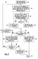
- Figure 2 is a flow diagram of a slot selection procedure for the uplink and downlink for a second embodiment in accordance with the present invention.
- Figure 3 is a flow diagram of a slot selection procedure for the uplink and downlink for a third embodiment in accordance with the present invention.
- a first embodiment of the present invention is directed to CAC with only common measurements available.
- the basic assignment procedure 10 for CAC in the uplink is shown.
- the procedure 10 commences with the first code in the code set (step 12).
- the load of an uplink time slot in cell i is defined as the load generated by the codes assigned in the same time slot in this cell and in first tier cells and second tier cells, since the load generated from cells beyond second tier is negligible.
- the load from neighboring cells is measured using the uplink time slot ISCP.
- Uplink time slot Interference Signal Code Power (ISCP) contains inter-cell interference only.
- the load after admission can be calculated as follows:
- the load from its own cell is called the intra-cell load Load UL_Intra ( i ) and is given by:
- Load UL_Intra i ⁇ UL ⁇ ⁇ h ⁇ ⁇ i SIR h where ⁇ ( i ) is the set of codes assigned in this time slot in the cell i .
- I intra N 0 1 - Load UL_Intra i
- the load after admission can be calculated as follows: The load of a time slot in cell j before admission is calculated using Equations 1-5, and denoted by Load UL_Before ( j ).
- Tier One ( i ) is the set of codes assigned in this time slot in tier-one neighboring cells of the cell i
- Tier Two(i) is the set of codes assigned in this time slot in tier-two neighboring cells of the cell i .
- CAC For CAC, a code will be admitted into a time slot in cell i only if, after admission, the following conditions can be satisfied in this time slot: Load UL i ⁇ CAC_Target_Load_Thres_UL and Load UL j ⁇ CAC_Neighbor_Load_Thres_UL , ⁇ j ⁇ Tier One i ⁇ Tier Two i
- CAC_Target_Load_Thres_UL is the admission threshold of load in the target cell
- CAC_Neighbor_Load_Thres_UL is the admission threshold of load in the neighboring cells.
- the new CCTrCH seeking admission has M codes in its code set to be assigned. These M codes are arranged in the order of increasing spreading factor, (decreasing required SIR target).
- the slot selection follows the procedures below:
- CaPwr ( i ) denote the carrier power of a downlink time slot in the cell i .
- SIR t denote the required SIR target of the code to be assigned in this time slot in the target cell i.
- X ⁇ j ⁇ TierOne i CaPwr j ⁇ PL i / PL j , for UE at different locations, (which implies different pathloss to BS), X is a random variable.
- ⁇ DL arg min ⁇ DL : Pr X ⁇ ⁇ DL ⁇ ⁇ j ⁇ TierOne i CaPwr j > ⁇
- 6 is a predefined percentage, for example, 90%.
- Y ⁇ j ⁇ TierTwo j CaPwr j ⁇ PL i / PL j , for UE at different locations, (which implies different pathloss to BS), Y is a random variable.
- a code will be admitted into a time slot in cell i only if after admission the following conditions can be satisfied in this time slot: CaPwr i ⁇ ⁇ ⁇ CaPwr maximum and CaPwr j ⁇ ⁇ ⁇ CaPwr maximum ⁇ j ⁇ Tier - One i ⁇ Tier - Two i
- CaPwr maximum is the maximum allowed carrier power at Node-B.
- the flowchart of the slot selection procedure in the downlink is the same as in the uplink (shown in Figure 1), except that call admission control in the downlink tries to minimize the average carrier power instead of average load.
- the new CCTrCH seeking admission has M codes in its code set to be assigned. Since the direction is downlink, the M codes have the same spreading factors 16 or 1. Therefore, the order of assignment for codes does not matter in the downlink.
- the slot selection follows the procedures below:
- the second embodiment of the present invention is directed to call admission control in the absence of measurements.
- a code will be admitted into a time slot in cell i only if after admission the following conditions can be satisfied in this time slot: Load UL i ⁇ CAC_Target_Load_Thres_UL and Load UL j ⁇ CAC_Neighbor_Load_Thres_UL , ⁇ j ⁇ Tier One i ⁇ Tier Two i
- CAC_Target_Load_Thres_UL is the admission threshold of load in the target cell
- CAC_Neighbor_Load_Thres_UL is the admission threshold of load in the neighboring cells.
- the flowchart of the slot selection procedure in the uplink is shown in Figure 2.
- the new CCTrCH seeking admission has M codes in its code set to be assigned. These M codes are arranged in the order of increasing spreading factor (decreasing required SIR target).
- the slot selection follows the procedures below:
- the load of a downlink time slot in cell i is defined as the load generated by the codes assigned in the same time slot in this cell and in first tier cells and second tier cells (load generated from cells beyond second tier is negligible). Therefore, the load in the downlink is similar to the load in the uplink. However, there is a difference between them. In the uplink, there is only one receiver, the BS. In the downlink, there are several receivers, UEs, scattered in the cell. To compensate for this difference, a scale factor is added into the load calculation.
- ⁇ DL is the average MUD residual factor in the downlink
- ⁇ DL is the weight factor for codes in the tier-one cells in the downlink
- ⁇ DL is the weight factor for codes in the tier-two cells in the downlink
- ⁇ ( k ) is the set of codes assigned in this time slot in the cell k
- Tier One ( k ) is the set of codes assigned in this time slot in tier-one neighboring cells of the cell k
- Tier Two(k) is the set of codes assigned in this time slot in tier-two neighboring cells of the cell k .
- a code will be admitted into a time slot in cell i only if after admission the following conditions can be satisfied in this time slot: Load DL i ⁇ CAC_Target_Load_Thres_DL and Load DL j ⁇ CAC_Neighbor_Load_Thres_DL , ⁇ j ⁇ Tier - One i ⁇ Tier - Two i
- CAC_Target_Load_Thres_DL is the admission threshold of load in the target cell
- CAC_Neighbor_Load_Thres_DL is the admission threshold of load in the neighboring cells.
- the flowchart of slot selection procedure is the same as in Figure 2.
- the new CCTrCH seeking admission has M codes in its code set to be assigned. Since the direction is downlink, the M codes have the same spreading factors 16 or 1. Therefore, the order of assignment for codes does not matter in the downlink.
- the slot selection follows the procedures below:
- the load of an uplink time slot in a cell is defined as the load generated by the users assigned in the same time slot in this cell and in first tier cells and second tier cells (load generated from cells beyond second tier is negligible).
- the load from neighboring cells is assumed to be a fixed ratio of the load from its own cell based on the assumption of homogeneous system. However, in a heterogeneous system, the load cannot be modeled in such a way. We compute the load from neighboring cells based its actual traffic.
- ⁇ UL is the average MUD residual factor in the uplink
- ⁇ UL is the weight factor for users in the tier-one cells in the uplink
- ⁇ UL is the weight factor for users in the tier-two cells in the uplink
- ⁇ ( k ) is the set of users assigned in this time slot in the cell k
- Tier One ( k ) is the set of users assigned in this time slot in tier-one neighboring cells of the cell k
- Tier Two ( k ) is the set of users assigned in this time slot in tier-two neighboring cells of the cell k .
- Equation 38 can written as: Load UL k ⁇ 1 - 1 N ⁇ R max or ⁇ UL ⁇ ⁇ h ⁇ ⁇ k SIR h + ⁇ UL ⁇ ⁇ h ⁇ Tier One k SIR h + ⁇ UL ⁇ ⁇ h ⁇ Tier Two k SIR h ⁇ 1 - 1 N ⁇ R max
- the call admission control function will try to minimize the total outage probability of the CCTrCH while making sure that the outage probability of assigned timeslots in neighboring cells also meets the requirements.
- the flowchart of the call admission control algorithm is shown in Figure 3.
- the new CCTrCH seeking admission in the target cell k has M codes in its code set to be assigned. These M codes are arranged in the order of increasing spreading factor (decreasing required SIR target).
- the slot selection follows the procedures below:
- the call admission control function in the downlink is similar to uplink. However, there are some differences in load definition and its physical meaning.
- the uplink there is only one receiver, the BS.
- the downlink there are several receivers, UEs, scattered in the cell.
- a scale factor is added into the load calculation. Then, the load is given by:
- outage probability computation and slot selection in the downlink are the same as in the uplink as shown in Figure 3.
Landscapes
- Engineering & Computer Science (AREA)
- Quality & Reliability (AREA)
- Computer Networks & Wireless Communication (AREA)
- Signal Processing (AREA)
- Mobile Radio Communication Systems (AREA)
Applications Claiming Priority (3)
| Application Number | Priority Date | Filing Date | Title |
|---|---|---|---|
| US38327302P | 2002-05-24 | 2002-05-24 | |
| US10/331,442 US6778812B1 (en) | 2002-05-24 | 2002-12-30 | System and method for call admission control |
| EP03729067A EP1510081B1 (de) | 2002-05-24 | 2003-05-22 | System und verfahren zur verbindungszulassungssteuerung |
Related Parent Applications (1)
| Application Number | Title | Priority Date | Filing Date |
|---|---|---|---|
| EP03729067A Division EP1510081B1 (de) | 2002-05-24 | 2003-05-22 | System und verfahren zur verbindungszulassungssteuerung |
Publications (2)
| Publication Number | Publication Date |
|---|---|
| EP1858286A2 true EP1858286A2 (de) | 2007-11-21 |
| EP1858286A3 EP1858286A3 (de) | 2008-01-23 |
Family
ID=38616238
Family Applications (1)
| Application Number | Title | Priority Date | Filing Date |
|---|---|---|---|
| EP07115881A Withdrawn EP1858286A3 (de) | 2002-05-24 | 2003-05-22 | System und Verfahren zur Rufzulassungssteuerung |
Country Status (1)
| Country | Link |
|---|---|
| EP (1) | EP1858286A3 (de) |
Family Cites Families (4)
| Publication number | Priority date | Publication date | Assignee | Title |
|---|---|---|---|---|
| US5734646A (en) * | 1995-10-05 | 1998-03-31 | Lucent Technologies Inc. | Code division multiple access system providing load and interference based demand assignment service to users |
| US6895245B2 (en) * | 1998-03-06 | 2005-05-17 | Telefonaktiebolaget Lm Ericssion(Publ) | Telecommunications interexchange measurement transfer |
| SE9801172D0 (sv) * | 1998-04-01 | 1998-04-01 | Ericsson Telefon Ab L M | Cell selection in a system with different cell capabilities |
| WO2000001189A1 (en) * | 1998-06-26 | 2000-01-06 | Telefonaktiebolaget Lm Ericsson (Publ) | Call admission control in wireless communication networks |
-
2003
- 2003-05-22 EP EP07115881A patent/EP1858286A3/de not_active Withdrawn
Also Published As
| Publication number | Publication date |
|---|---|
| EP1858286A3 (de) | 2008-01-23 |
Similar Documents
| Publication | Publication Date | Title |
|---|---|---|
| EP1510081B1 (de) | System und verfahren zur verbindungszulassungssteuerung | |
| EP1530304B1 (de) | Basisstation und Sendeleistungsregelungsverfahren in einem mobilen Kommunikationssystem | |
| US6985700B1 (en) | Power estimation method | |
| US9232523B2 (en) | Allocating resources for shared and non-shared downlink wireless resources | |
| EP2223451B1 (de) | Verwürflungskodezuteilung in einem cellularen kommunikationsnetz | |
| EP1602186B1 (de) | System und verfahren mit adaptiven antennen zur selektiven wiederverwendung von zeitschlitzen des gemeinsamen physischen kanals für fest zugeordnete kanäle | |
| KR100801517B1 (ko) | 하이브리드 tdma/cdma 통신 시스템에서의 채널할당 방법 및 시스템 | |
| US6782263B1 (en) | Dynamic channel allocation method in cellular radio network and system for channel allocation | |
| EP1687904B1 (de) | Drahtloses kommunikationsverfahren und vorrichtung zum implementieren einer verbindungszulassungsregelung auf der basis gemeinsamer messungen | |
| CN1307850C (zh) | 一种无线通信系统接纳控制方法 | |
| KR100552129B1 (ko) | 활성 세트에 대한 후보 셀 결정 방법 | |
| EP1772035B1 (de) | Verfahren und system zur regelung der zulassung in mobilkommunikationsnetzen, diesbezügliches netz und computerprogrammprodukt dafür | |
| EP1858286A2 (de) | System und Verfahren zur Rufzulassungssteuerung | |
| EP1931166A1 (de) | Rufzulassungssteuerung | |
| JP2006517762A (ja) | 専用チャネルのためにcpchタイムスロットの選択的再使用するためのアダプティブアンテナを用いたシステムおよび方法 | |
| EP1835645A1 (de) | System und Verfahren mit adaptiven Antennen zur selektiven Wiederverwendung von Zeitschlitzen des gemeinsamen physischen Kanals für fest zugeordnete Kanäle |
Legal Events
| Date | Code | Title | Description |
|---|---|---|---|
| PUAI | Public reference made under article 153(3) epc to a published international application that has entered the european phase |
Free format text: ORIGINAL CODE: 0009012 |
|
| 17P | Request for examination filed |
Effective date: 20070907 |
|
| AC | Divisional application: reference to earlier application |
Ref document number: 1510081 Country of ref document: EP Kind code of ref document: P |
|
| AK | Designated contracting states |
Kind code of ref document: A2 Designated state(s): AT BE BG CH CY CZ DE DK EE ES FI FR GB GR HU IE IT LI LU MC NL PT RO SE SI SK TR |
|
| AX | Request for extension of the european patent |
Extension state: AL BA HR MK YU |
|
| PUAL | Search report despatched |
Free format text: ORIGINAL CODE: 0009013 |
|
| AK | Designated contracting states |
Kind code of ref document: A3 Designated state(s): AT BE BG CH CY CZ DE DK EE ES FI FR GB GR HU IE IT LI LU MC NL PT RO SE SI SK TR |
|
| AX | Request for extension of the european patent |
Extension state: AL BA HR MK YU |
|
| RIC1 | Information provided on ipc code assigned before grant |
Ipc: H04B 17/00 20060101ALI20071217BHEP Ipc: H04Q 7/20 20060101ALI20071217BHEP Ipc: H04Q 7/00 20060101AFI20071217BHEP |
|
| STAA | Information on the status of an ep patent application or granted ep patent |
Free format text: STATUS: THE APPLICATION HAS BEEN WITHDRAWN |
|
| 18W | Application withdrawn |
Effective date: 20080722 |