EP1859193B1 - Collecteur pour fluides - Google Patents
Collecteur pour fluides Download PDFInfo
- Publication number
- EP1859193B1 EP1859193B1 EP06711092A EP06711092A EP1859193B1 EP 1859193 B1 EP1859193 B1 EP 1859193B1 EP 06711092 A EP06711092 A EP 06711092A EP 06711092 A EP06711092 A EP 06711092A EP 1859193 B1 EP1859193 B1 EP 1859193B1
- Authority
- EP
- European Patent Office
- Prior art keywords
- manifold
- coupling
- female
- male
- offtake
- Prior art date
- Legal status (The legal status is an assumption and is not a legal conclusion. Google has not performed a legal analysis and makes no representation as to the accuracy of the status listed.)
- Expired - Lifetime
Links
Images

Classifications
-
- F—MECHANICAL ENGINEERING; LIGHTING; HEATING; WEAPONS; BLASTING
- F16—ENGINEERING ELEMENTS AND UNITS; GENERAL MEASURES FOR PRODUCING AND MAINTAINING EFFECTIVE FUNCTIONING OF MACHINES OR INSTALLATIONS; THERMAL INSULATION IN GENERAL
- F16L—PIPES; JOINTS OR FITTINGS FOR PIPES; SUPPORTS FOR PIPES, CABLES OR PROTECTIVE TUBING; MEANS FOR THERMAL INSULATION IN GENERAL
- F16L41/00—Branching pipes; Joining pipes to walls
- F16L41/02—Branch units, e.g. made in one piece, welded, riveted
- F16L41/03—Branch units, e.g. made in one piece, welded, riveted comprising junction pieces for four or more pipe members
-
- F—MECHANICAL ENGINEERING; LIGHTING; HEATING; WEAPONS; BLASTING
- F16—ENGINEERING ELEMENTS AND UNITS; GENERAL MEASURES FOR PRODUCING AND MAINTAINING EFFECTIVE FUNCTIONING OF MACHINES OR INSTALLATIONS; THERMAL INSULATION IN GENERAL
- F16L—PIPES; JOINTS OR FITTINGS FOR PIPES; SUPPORTS FOR PIPES, CABLES OR PROTECTIVE TUBING; MEANS FOR THERMAL INSULATION IN GENERAL
- F16L41/00—Branching pipes; Joining pipes to walls
- F16L41/02—Branch units, e.g. made in one piece, welded, riveted
- F16L41/021—T- or cross-pieces
-
- F—MECHANICAL ENGINEERING; LIGHTING; HEATING; WEAPONS; BLASTING
- F24—HEATING; RANGES; VENTILATING
- F24D—DOMESTIC- OR SPACE-HEATING SYSTEMS, e.g. CENTRAL HEATING SYSTEMS; DOMESTIC HOT-WATER SUPPLY SYSTEMS; ELEMENTS OR COMPONENTS THEREFOR
- F24D3/00—Hot-water central heating systems
- F24D3/10—Feed-line arrangements, e.g. providing for heat-accumulator tanks, expansion tanks ; Hydraulic components of a central heating system
- F24D3/1058—Feed-line arrangements, e.g. providing for heat-accumulator tanks, expansion tanks ; Hydraulic components of a central heating system disposition of pipes and pipe connections
- F24D3/1066—Distributors for heating liquids
-
- F—MECHANICAL ENGINEERING; LIGHTING; HEATING; WEAPONS; BLASTING
- F24—HEATING; RANGES; VENTILATING
- F24D—DOMESTIC- OR SPACE-HEATING SYSTEMS, e.g. CENTRAL HEATING SYSTEMS; DOMESTIC HOT-WATER SUPPLY SYSTEMS; ELEMENTS OR COMPONENTS THEREFOR
- F24D3/00—Hot-water central heating systems
- F24D3/10—Feed-line arrangements, e.g. providing for heat-accumulator tanks, expansion tanks ; Hydraulic components of a central heating system
- F24D3/1058—Feed-line arrangements, e.g. providing for heat-accumulator tanks, expansion tanks ; Hydraulic components of a central heating system disposition of pipes and pipe connections
- F24D3/1066—Distributors for heating liquids
- F24D3/1075—Built up from modules
Definitions
- the present invention relates to a manifold for fluids comprising at least a quick action coupling suitable for being connected to other manifolds, pipe fittings, pipings and hydraulic devices in general for supplying fluids.
- the present invention relates to manifolds comprising interlocking quick couplings suitable for allowing various fluids to be supplied such as water, oil, compressed air or the like, in houses or industrial structures.
- manifold is used as referring to devices for supplying fluids comprising a main inlet and a main outlet (inlet gate and outlet gate), of course reversible one with the other, and one or more side outlets (offtakes), generally having smaller dimensions, for allowing either the flow the fluid or controlling parameters of the fluid (temperature, capacity, etc).
- Such kinds of manifolds are generally used for supplying fluids in residential environments.
- such manifolds are used for receiving a warm water piping at their main inlet coming from the boiler and for supplying the water to a plurality of heating bodies (radiating panels or heaters, pipes, etc) through the offtakes of the building.
- manifolds are connected one to another at their outlet so as to allow water to be supplied at a plurality of offtakes.
- manifolds can also be used, as an example, for supplying sanitary water or compressed air and/or various fluids.
- an example of manifold is known from the patent document published with the number WO01/71236 provided with a quick action coupling of interlocking kind in which a male element (male) and a corresponding female element (female) are provided, at the main inlet and at the main outlet (outlet), suitable for being connected or coupled by interlocking with other manifolds or hydraulic devices, by means of a quick coupling.
- the male and the female are provided with respective protrusions or projections consisting of two annular segments suitable for being coupled with interlocking by inserting the male in the female and by rotating thereafter one of the elements relative to the other by approximately 90°.
- the protrusions are at sight (visible) in order to allowing an operator to easily recognise the correct mutual connection easy, as an example, of many manifolds.
- a problem of the cited background art is that the protrusions, protruding from the outline of the coupling, can be hit and damaged before and during the assembly.
- the protrusions in particular the protrusion of the female, always since they protrude from the outline of the coupling, as an example can be broken or damaged due to accidental hits and also be uncoupled of disconnected from the coupling.
- the coupling particularly complex, comprises a male and a female suitable for being coupled each with the other by interlocking.
- the male and the female -the latter being protected by a guard- comprise respective helic-shaped fins.
- the rotation of one of the fins relative to the other is controlled with a mechanical stop arranged inside the fin of the female.
- a first problem of this kind of couplings is that the relative rotation of the male relative to the female is controlled by means of the mechanical stop in the female, the female being protected by the guard, and therefore the possible dirt on the mechanical stop can prevent the coupling from being completely closed.
- EP 1045209 discloses a distributor for fluids having several interconnected housings for containing valves, flow-meter, thermal sensors especially.
- the housings have an axially continuous main duct and at least one transverse duct connected to the main duct.
- a male extension to the main duct is inserted to a female part of the main duct of the adjoining housing.
- the male extension has at least one radially projecting lug which is part of a bayonet fastening and which cooperates with corresponding cavities in the inner wall of the female part having sections running in an axial and peripheral direction.
- EP 1 045 209 discloses the following features cited in the appended claim 1, namely a manifold for fluids comprising a main inlet and a main outlet for a fluid, and at least one offtake for supplying said fluid or checking features of said fluid, comprising at least one quick coupling female element associated to said main outlet and suitable for being coupled during use with a corresponding quick coupling male element so as to provide a quick action coupling; said manifold comprising a quick coupling male element associated to said main inlet, and suitable for being coupled during use with a corresponding quick coupling female element so as to provide a quick action coupling; said at least a quick coupling female element comprising a protecting shell having a depth equal or greater than the length of said quick coupling male element and substantially an annular shape, and being arranged so as to protect during use said corresponding quick coupling male element; said manifold comprising at least a coupling reference visible from the outside and suitable for allowing the carrying out of said quick action coupling to be visually checked; the
- CH 694438 discloses a pipe coupling locking device comprising a locking piece in the form of a tubular segment, which fits into one of the intermediate spaces defined by inner and outer cams of the interfitting pipe sections of the assembled pipe coupling.
- WO 9901701 Another type of manifold which is made of plastic parts and can be joined to a similar manifold without rotation is disclosed in WO 9901701 . According to this arrangement a notch is provided in an internal rib in the male connector end sized to engage a locking tab carried by the female connector end so that two similar manifold segments could be inserted together and thereby joined without rotation.
- An object of the present invention is solving the problems of the background art previously set forth.
- At least a of the manifold offtakes is positioned so as to indicate the perfect closing of the coupling.
- the manifold can be made of metallic material and manufactured by casting and turning.
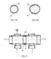
- a manifold for fluids (manifold) 10 according to the invention comprises as an example:
- the manifold 10 comprises a first offtake 11 for supplying fluids and, in alternative embodiments, as an example, a second offtake 12 like shown in Figures 2 and 4 or further offtakes.
- first and second offtake, 11 and 12 are provided with threads of known kind so as to allow themselves to be connected, in a known way, with corresponding threads as an example of pipes or pipe fittings.
- offtakes can also being provided with quick action coupling elements according to the present invention.
- the male element 15 comprises a seal seat 21 ( Figures 1 to 4 ), as an example having rectangular shape, and arranged so as to house a toroidal gasket (gasket) 17.
- gasket as described in further detail hereinafter, is suitable for providing, in known way, a fluid-tight coupling.
- the male element 15 further comprises a pair of annular male segments (fins of the male) 26 and a ring-like male recess (male recess) 27, as an example having rectangular cross-section, suitable for cooperating in known way with a corresponding pair of annular female segments (fins of the female) 36 and a corresponding ring-like female recess (female recess) 37 so as to realize the coupling according to the invention.
- couples of fins, male 26 and female 36 respectively as an example extend as a circle or radially and extend over a circular sector of about 90°; the couples of fins 26 and 36 respectively are suitable for being coupled together, as it will be describer hereinafter in further detail, through a rotation as an example of the male 15 relative to the female 16 by about 90°.
- the recesses 27 and 37 respectively are suitable for housing, in a known way, the pairs of annular segments 36 and 26 respectively and, in the preferred embodiment, extend as an example, over the whole circumference and are not provided with any mechanical stop element.
- pairs of annular segments or fins male 26 and female 36 respectively, are arranged so as to have a symmetry axis aligned with the first offtake 11.
- the pairs of fins can be arranged symmetrically relative to the vertical axis.
- pairs of annular segments or fins are made so as to be positioned in relative identical positions relative to the first 11 or to the second offtake 12 respectively, or to at least one of the offtakes.
- This kind of configuration is such to allow the male 15 and the female 16 to be completely coupled using the first 11 or the second offtake 12 of the manifold 10 as coupling reference, with no need of mechanical stop elements inside the manifold or of shaping the elements of the coupling as protrusions.
- the coupling reference can be associated to suitable indications provided on the manifold or on the element to be connected to the manifold, and however arranged so as to keep a predetermined relation with the pair of fins, male 26 and female 36 respectively, instead of being associated to one of the offtakes.
- the female element 16 comprises a protection shell (shell) 33 substantially shaped as an outer circular ring and suitable for protecting the male element 15 during use.
- shell protection shell
- the shell 33 has a depth equal to or greater than the length of the male 15 and inside is shaped so as to comprise, starting from the inner part, the female recess 37, the pair of female fins 36 and a substantially flat surface (inner surface of the shell) extending towards the outside of the main outlet 30.
- the shell 33 is externally shaped with a substantially hexagonal cross-section, but any other alternative shape, compatible with the function of protecting external shell, can also be used.
- connection procedure After having aligned the two manifolds 10 comprising, as an example, one or two offtakes, so that the first offtake 11 of a first manifold 10 is oriented at an angle of 90° relative to the first offtake 11 of a second manifold 10, the connection procedure provides for a substantially axial force along the outlet axis 20, 30 to be applied, such force being suitable for allowing the male 15 of the first manifold 10 to be fitted in the female 16 of the second manifold.
- the gasket 17 is suitable for applying a substantially radial pressure relative to the longitudinal axis of the manifolds on the inner surface of the shell 33.
- one of the two manifolds is rotated in a whichever direction, so as to align the first offtake 11 of the first manifold with the first offtake 11 of the second manifold.
- connection of the two manifolds is terminated so that the pairs of annular segments, the male 26 and the female 36 respectively, are suitable for ensuring a fluid-tight axial sealing and the gasket 17 is suitable for ensuring the radial fluid-tight sealing of the coupling so obtained.
- the alignment in the fitting- and coupling phase can be carried out using suitable indications provided on the manifold and on the hydraulic device to be coupled, instead of the offtakes.
- the coupling so obtained provides the advantage that is fully protected by the guard 33 so that no body can hit the coupling elements and cause damages or the coupling itself to be accidentally disassembled. Moreover the pipes or hydraulic devices connected to the offtakes will keep the position stable.
- the coupling does not require any mechanical stop element associated to the coupling elements, since the completion of the connection can be checked visually from the outside and therefore the coupling is not subject to assembly errors.
- the described manifold has a very simple manufacture. In fact such manifold requires, as a technician skilled in the technical field can easily understand, simple mechanical workings, such as making recesses (grooves) on the male element and on the female element.
- the manifold can therefore be made of metallic material, such as brass, aluminum and, for diameters greater as an example than 50 millimeters, also of steel, through forming or forging or casting and finish by turning thereafter.
- manifold can also be made of plastic material by molding.
Landscapes
- Engineering & Computer Science (AREA)
- General Engineering & Computer Science (AREA)
- Mechanical Engineering (AREA)
- Physics & Mathematics (AREA)
- Thermal Sciences (AREA)
- Chemical & Material Sciences (AREA)
- Combustion & Propulsion (AREA)
- Quick-Acting Or Multi-Walled Pipe Joints (AREA)
- Laminated Bodies (AREA)
- Acyclic And Carbocyclic Compounds In Medicinal Compositions (AREA)
Claims (6)
- Collecteur pour fluides comprenant un orifice d'entrée principal (20) et un orifice de sortie principal (30) destinés à un fluide, et au moins un soutirage (11) pour fournir dudit fluide ou pour vérifier des caractéristiques dudit fluide, comportant un élément femelle de couplage rapide (16) associé audit orifice de sortie principal (30) et approprié pour être couplé lors de l'utilisation avec un élément mâle de couplage rapide correspondant (15) de façon à fournir un couplage à action rapide ;
ledit collecteur comprenant un élément mâle de couplage rapide (15) associé au dit orifice d'entrée principal (20), et approprié pour être couplé lors de l'utilisation avec un élément femelle de couplage rapide correspondant (16) de façon à fournir un couplage à action rapide ;
ledit élément femelle de couplage rapide (16) comportant une enveloppe de protection (33) présentant une profondeur égale ou supérieure à la longueur dudit élément mâle de couplage rapide (15) et essentiellement une configuration annulaire, et étant agencé de façon à protéger lors de l'utilisation ledit élément mâle de couplage rapide correspondant (15) ;
ledit collecteur comprenant au moins une référence de couplage visible de l'extérieur et appropriée pour permettre de contrôler visuellement la réalisation dudit couplage à action rapide ;
l'élément mâle (15) comprenant, de plus, une paire de segments annulaires mâles (26) et un évidement mâle en forme d'anneau (27), appropriés pour coopérer avec une paire correspondante de segments annulaires femelles (36) et avec un évidement femelle en forme d'anneau correspondant (37) ;
ladite enveloppe de protection (33) étant configurée à l'intérieur de façon à comprendre, démarrant à partir de la partie intérieure, l'évidement femelle (37), la paire de segments femelles (36) et une surface interne essentiellement lisse de l'enveloppe (33) s'étendant vers l'extérieur de l'orifice de sortie principal (30) ;
les couples de segments mâles (26) et de segments femelles (36) s'étendant sous la forme d'un cercle ou de façon radiale sur un secteur circulaire d'environ 90° et étant agencés de façon à comporter un axe de symétrie aligné avec un premier soutirage (11) de façon à être positionnés dans des positions relatives identiques par rapport au dit premier soutirage (11) ;
de sorte que deux desdits collecteurs (10) peuvent être couplés en orientant un soutirage (11) d'un premier collecteur (10) suivant un angle de 90° par rapport à un premier soutirage (11) d'un second collecteur (10), en appliquant une force essentiellement axiale appropriée pour permettre à l'élément mâle (15) du premier collecteur (10) de s'ajuster dans l'élément femelle (16) du second collecteur (10) et en faisant tourner l'un des deux collecteurs dans une direction quelconque, de façon à aligner le premier soutirage (11) du premier collecteur avec le premier soutirage (11) du second collecteur. - Collecteur suivant la revendication 1, dans lequel un élément fileté d'un couplage est associé à au moins un soutirage (11).
- Collecteur selon la revendication 1, dans lequel ledit au moins un soutirage (11) peut être agencé comme étant ladite au moins une référence de couplage visible de l'extérieur.
- Collecteur selon la revendication 1, dans lequel ledit élément mâle de couplage rapide (15) comporte un autre évidement circulaire (21) approprié pour loger un joint d'étanchéité.
- Collecteur selon la revendication 1, caractérisé par le fait d'être constitué d'un matériau métallique.
- Collecteur selon la revendication 5, caractérisé par le fait d'être réalisé par formage ou par forgeage ou par moulage et ensuite par finition mécanique.
Applications Claiming Priority (2)
| Application Number | Priority Date | Filing Date | Title |
|---|---|---|---|
| IT000035U ITTO20050035U1 (it) | 2005-03-15 | 2005-03-15 | Collettore per fluidi |
| PCT/IB2006/050787 WO2006097892A2 (fr) | 2005-03-15 | 2006-03-14 | Collecteur pour fluides |
Publications (2)
| Publication Number | Publication Date |
|---|---|
| EP1859193A2 EP1859193A2 (fr) | 2007-11-28 |
| EP1859193B1 true EP1859193B1 (fr) | 2010-12-15 |
Family
ID=36992110
Family Applications (1)
| Application Number | Title | Priority Date | Filing Date |
|---|---|---|---|
| EP06711092A Expired - Lifetime EP1859193B1 (fr) | 2005-03-15 | 2006-03-14 | Collecteur pour fluides |
Country Status (9)
| Country | Link |
|---|---|
| US (1) | US20080111376A1 (fr) |
| EP (1) | EP1859193B1 (fr) |
| CN (1) | CN101142433B (fr) |
| AT (1) | ATE491910T1 (fr) |
| DE (1) | DE602006018876D1 (fr) |
| ES (1) | ES2359568T3 (fr) |
| IT (1) | ITTO20050035U1 (fr) |
| RU (1) | RU2406912C2 (fr) |
| WO (1) | WO2006097892A2 (fr) |
Cited By (2)
| Publication number | Priority date | Publication date | Assignee | Title |
|---|---|---|---|---|
| EP2492573A1 (fr) | 2011-02-25 | 2012-08-29 | Orkli, S. Coop. | Collecteur à couplage rapide particulièrement adapté pour systèmes de chauffage ou de plomberie |
| EP4425026A1 (fr) * | 2023-03-01 | 2024-09-04 | Uponor Innovation AB | Pièce de tuyau et raccord entre deux pièces de tuyau |
Families Citing this family (35)
| Publication number | Priority date | Publication date | Assignee | Title |
|---|---|---|---|---|
| ITTO20070013A1 (it) | 2007-01-09 | 2008-07-10 | Riccardo Ferrero | Impianto di climatizzazione, unita di distribuzione e valvola di distribuzione per tale impianto, e metodo per il condizionamento termico di un edificio tramite tale impianto. |
| DE102007010116B4 (de) * | 2007-02-28 | 2010-08-26 | AFRISO Euro-Index GmbH für Sicherungsarmaturen und Füllstandsmessung | Warmwasserverteiler einer Fußbodenheizung sowie Verfahren zur Herstellung eines Verteilerrohrs des Warmwasserverteilers |
| CN101802515A (zh) | 2007-06-19 | 2010-08-11 | 丹佛斯公司 | 具备分配器的膨胀阀 |
| US8549875B2 (en) | 2007-06-19 | 2013-10-08 | Danfoss A/S | Modular valve |
| ATE527488T1 (de) * | 2007-12-06 | 2011-10-15 | Wavin Bv | Fluidverteiler für ein heiz- und/oder kühlsystem |
| ITGE20090023A1 (it) * | 2009-04-24 | 2010-10-25 | Comer Spa | Collettore modulare |
| NL2003026C2 (nl) * | 2009-06-15 | 2010-12-16 | Tideway B V | Buisvormig element van een valpijp, uit dergelijke elementen opgebouwde valpijp, koppeling tussen twee dergelijke buisvormige elementen, en werkwijze voor het opbouwen van de valpijp. |
| ES2390544B1 (es) * | 2009-09-21 | 2013-11-07 | Domingo CARRILERO ALCARAZ | Manguito ensablaje |
| ES2579958T3 (es) * | 2009-10-21 | 2016-08-17 | Biocartis Nv | Colector para un cartucho fluídico |
| USD654990S1 (en) * | 2010-01-27 | 2012-02-28 | Class 1, Inc. | Fluid pipe |
| CN102242619A (zh) * | 2010-05-12 | 2011-11-16 | 浙江双环塑胶阀门有限公司 | 变径分支井筒检查井 |
| US8465268B2 (en) * | 2010-09-10 | 2013-06-18 | Phoinix Global LLC | Compression clamp for a modular fluid end for a multiplex plunger pump |
| FR2970539A1 (fr) * | 2011-01-14 | 2012-07-20 | Fabrice Philippe Thierry Chappuis | Module individuel pour collecteur de circuit d'eau de plancher chauffant |
| USD730496S1 (en) * | 2012-11-06 | 2015-05-26 | Michael Schulze | Plumbing pipe |
| USD729910S1 (en) * | 2013-05-15 | 2015-05-19 | MPS Technologies, LLC | Plumbing pipe |
| GB201322738D0 (en) * | 2013-12-20 | 2014-02-05 | Agco Int Gmbh | Hydraulic coupling seal |
| CN104776482A (zh) * | 2015-05-04 | 2015-07-15 | 马卓娅 | 一种暖气管道分接机构 |
| CN106861008B (zh) * | 2015-12-14 | 2020-07-17 | 北京谊安医疗系统股份有限公司 | 一种盲插接头 |
| US10690356B2 (en) * | 2016-04-13 | 2020-06-23 | Paul D Mercier, SR. | Enhanced convection, differential temperature managed, hydronic heating appliance |
| CN106122647A (zh) * | 2016-09-12 | 2016-11-16 | 周杰 | 一种风机管道对接用t型三通快速接头 |
| CN106402552A (zh) * | 2016-11-26 | 2017-02-15 | 华南理工大学 | 一种可拆卸的两自由度的管道连接结构 |
| USD814104S1 (en) * | 2016-12-14 | 2018-03-27 | Michael Masoud Mahinfar | Cover |
| DE202017101386U1 (de) * | 2017-03-10 | 2017-05-10 | Watts Industries Deutschland Gmbh | Armatur |
| CN110081506A (zh) * | 2019-05-31 | 2019-08-02 | 章根友 | 一种暖气件连接结构和暖气组件 |
| EP4232738A1 (fr) | 2020-10-26 | 2023-08-30 | Oetiker NY, Inc. | Ensemble de raccordement de fluide |
| KR102798617B1 (ko) | 2020-10-26 | 2025-04-23 | 외티커 엔와이, 인크. | 유체 연결 조립체 |
| WO2022093167A1 (fr) | 2020-10-26 | 2022-05-05 | Oetiker Ny, Inc. | Ensemble de raccordement de fluide |
| JP7611377B2 (ja) | 2020-10-26 | 2025-01-09 | オエティカ エヌワイ インク | 流体接続アセンブリ |
| CN112539445B (zh) * | 2020-12-03 | 2022-04-22 | 山东得辰建设工程有限公司 | 一种换热站供暖管网及供暖系统 |
| US12410876B2 (en) | 2021-06-02 | 2025-09-09 | Oetiker Ny, Inc. | Fluid connection assembly |
| WO2023196021A1 (fr) * | 2022-04-05 | 2023-10-12 | Oetiker Ny, Inc. | Ensemble de raccordement de fluide |
| US12078277B2 (en) | 2022-07-21 | 2024-09-03 | Applied System Technologies, Inc. | Coupling for connecting two sections of piping |
| US12313109B2 (en) | 2022-07-21 | 2025-05-27 | Applied System Technologies, Inc. | End nut assembly |
| US12000519B2 (en) | 2022-10-24 | 2024-06-04 | Applied System Technologies, Inc. | Coupling for connecting two sections of piping with water trap |
| CN119617215A (zh) * | 2024-11-27 | 2025-03-14 | 中国船舶重工集团应急预警与救援装备股份有限公司 | 一种模块化管路转换接头 |
Family Cites Families (14)
| Publication number | Priority date | Publication date | Assignee | Title |
|---|---|---|---|---|
| US261191A (en) * | 1882-07-18 | Sectional pipe | ||
| US3506029A (en) * | 1968-06-28 | 1970-04-14 | Amp Inc | Manifold sections to construct a manifold |
| US4338793A (en) * | 1979-08-10 | 1982-07-13 | Hern Jr James E O | Adapter for refrigeration system access valve |
| IT8648373A0 (it) * | 1986-08-08 | 1986-08-08 | Santoro Gennaro | Scambiatore termico |
| CN2098606U (zh) * | 1991-09-03 | 1992-03-11 | 伍宇航 | 快捷方便随机拼装式管道连接系统 |
| JP2002515825A (ja) | 1996-02-27 | 2002-05-28 | スプレイング システムズ カンパニー | 急速脱着式スプレーチップを有するノズル |
| US5868439A (en) * | 1997-07-02 | 1999-02-09 | Schmidt; Garry | Distribution header for potable water and hot water space heating |
| ATE245787T1 (de) * | 1999-04-16 | 2003-08-15 | Multitherm Fussboden Heizung G | Verteiler |
| FR2793867B1 (fr) * | 1999-05-20 | 2001-06-29 | Comap Abbeville | Module pour un collecteur pour distribution de fluide et systeme de fixation pour de tels modules |
| US6213243B1 (en) * | 1999-05-21 | 2001-04-10 | Navistar International Transportation Corp. | Dual draw and return fuel manifold with integral mounting bracket for a vehicle |
| CH694438A5 (de) * | 1999-12-08 | 2005-01-14 | Von Roll Infranet Sa | Verriegelung für Rohrverbindungen und eine solche Verriegelung aufweisende Rohrverbindung, sowie eine Armatur mit einer entsprechenden Rohrverbindung. |
| CN1216246C (zh) * | 2000-03-20 | 2005-08-24 | 贾科米尼公开有限公司 | 用于供热和卫生系统的改进模块式歧管和改进的歧管模块 |
| AU2002235230A1 (en) * | 2000-12-18 | 2002-07-01 | Colder Products Company | Dispensing valve assembly for liquid |
| DE10163785A1 (de) * | 2001-12-22 | 2003-07-03 | Mueller A & K Gmbh Co Kg | Einrichtung zum Zusammenschalten mehrerer hydraulischer oder pneumatischer Komponenten, insbesondere mehrerer Elektromagnetventile |
-
2005
- 2005-03-15 IT IT000035U patent/ITTO20050035U1/it unknown
-
2006
- 2006-03-14 RU RU2007138026/06A patent/RU2406912C2/ru not_active IP Right Cessation
- 2006-03-14 EP EP06711092A patent/EP1859193B1/fr not_active Expired - Lifetime
- 2006-03-14 WO PCT/IB2006/050787 patent/WO2006097892A2/fr not_active Ceased
- 2006-03-14 AT AT06711092T patent/ATE491910T1/de not_active IP Right Cessation
- 2006-03-14 ES ES06711092T patent/ES2359568T3/es not_active Expired - Lifetime
- 2006-03-14 DE DE602006018876T patent/DE602006018876D1/de not_active Expired - Lifetime
- 2006-03-14 CN CN2006800083436A patent/CN101142433B/zh not_active Expired - Fee Related
- 2006-03-14 US US11/908,926 patent/US20080111376A1/en not_active Abandoned
Cited By (2)
| Publication number | Priority date | Publication date | Assignee | Title |
|---|---|---|---|---|
| EP2492573A1 (fr) | 2011-02-25 | 2012-08-29 | Orkli, S. Coop. | Collecteur à couplage rapide particulièrement adapté pour systèmes de chauffage ou de plomberie |
| EP4425026A1 (fr) * | 2023-03-01 | 2024-09-04 | Uponor Innovation AB | Pièce de tuyau et raccord entre deux pièces de tuyau |
Also Published As
| Publication number | Publication date |
|---|---|
| WO2006097892A3 (fr) | 2007-02-15 |
| CN101142433B (zh) | 2010-10-13 |
| EP1859193A2 (fr) | 2007-11-28 |
| RU2007138026A (ru) | 2009-04-20 |
| ITTO20050035U1 (it) | 2006-09-16 |
| RU2406912C2 (ru) | 2010-12-20 |
| CN101142433A (zh) | 2008-03-12 |
| DE602006018876D1 (de) | 2011-01-27 |
| ATE491910T1 (de) | 2011-01-15 |
| US20080111376A1 (en) | 2008-05-15 |
| ES2359568T3 (es) | 2011-05-24 |
| WO2006097892A2 (fr) | 2006-09-21 |
Similar Documents
| Publication | Publication Date | Title |
|---|---|---|
| EP1859193B1 (fr) | Collecteur pour fluides | |
| JP5086408B2 (ja) | 角度をなす空洞を有する継手の使用方法 | |
| CN201739683U (zh) | 旋转卡扣式管道接头 | |
| KR200467280Y1 (ko) | 분기용 배관 | |
| AU637116B2 (en) | Improvements to pipe couplings | |
| US20250230894A1 (en) | Pipe Assembly Insulation and Vapor Barrier | |
| WO2007057629A1 (fr) | Accouplement pour conduite de carburant d’aeronef | |
| RU2551912C2 (ru) | Соединение между двумя элементами трубопровода | |
| US6712027B2 (en) | Hot water heating system and connector for use therewith | |
| US11480273B2 (en) | Fluid coupling | |
| US5171042A (en) | Spigot joint for lined metallic pipes particularly for fluids | |
| KR101232319B1 (ko) | 파이프 연결구 | |
| US11346478B2 (en) | Connector for circuit elements | |
| EP2681494A1 (fr) | Dispositif adaptateur pour relier un élément de radiateur à un système de plomberie | |
| EP2492573A1 (fr) | Collecteur à couplage rapide particulièrement adapté pour systèmes de chauffage ou de plomberie | |
| KR101135061B1 (ko) | 환상보호캡이 구비된 기밀유지용 밸브소켓 및 이의 제조방법 | |
| EP1724509A2 (fr) | Raccord de tuyaux à angle variable | |
| KR200448339Y1 (ko) | 회전식 각도조절 연결관 | |
| EP2975312B1 (fr) | Système de refroidissement d'un flux ou pour extraire la chaleur d'un flux dans un pipeline et/ou pour extraire la chaleur hors de l'environnement d'un pipeline | |
| WO2015107120A2 (fr) | Vanne de raccordement rapide sec | |
| KR200456652Y1 (ko) | 분배기 조립체 | |
| EP3730827B1 (fr) | Joint démontable étanche à l'eau | |
| EP1031809A1 (fr) | Elément modulaire pour radiateurs | |
| EP1122483B1 (fr) | Raccord de tuyaux | |
| EP3155306B1 (fr) | Raccord de connexion réglable |
Legal Events
| Date | Code | Title | Description |
|---|---|---|---|
| PUAI | Public reference made under article 153(3) epc to a published international application that has entered the european phase |
Free format text: ORIGINAL CODE: 0009012 |
|
| 17P | Request for examination filed |
Effective date: 20070802 |
|
| AK | Designated contracting states |
Kind code of ref document: A2 Designated state(s): AT BE BG CH CY CZ DE DK EE ES FI FR GB GR HU IE IS IT LI LT LU LV MC NL PL PT RO SE SI SK TR |
|
| DAX | Request for extension of the european patent (deleted) | ||
| 17Q | First examination report despatched |
Effective date: 20080905 |
|
| GRAP | Despatch of communication of intention to grant a patent |
Free format text: ORIGINAL CODE: EPIDOSNIGR1 |
|
| GRAS | Grant fee paid |
Free format text: ORIGINAL CODE: EPIDOSNIGR3 |
|
| GRAA | (expected) grant |
Free format text: ORIGINAL CODE: 0009210 |
|
| AK | Designated contracting states |
Kind code of ref document: B1 Designated state(s): AT BE BG CH CY CZ DE DK EE ES FI FR GB GR HU IE IS IT LI LT LU LV MC NL PL PT RO SE SI SK TR |
|
| REG | Reference to a national code |
Ref country code: GB Ref legal event code: FG4D Ref country code: CH Ref legal event code: EP |
|
| REG | Reference to a national code |
Ref country code: IE Ref legal event code: FG4D |
|
| REF | Corresponds to: |
Ref document number: 602006018876 Country of ref document: DE Date of ref document: 20110127 Kind code of ref document: P |
|
| REG | Reference to a national code |
Ref country code: NL Ref legal event code: VDEP Effective date: 20101215 |
|
| PG25 | Lapsed in a contracting state [announced via postgrant information from national office to epo] |
Ref country code: LT Free format text: LAPSE BECAUSE OF FAILURE TO SUBMIT A TRANSLATION OF THE DESCRIPTION OR TO PAY THE FEE WITHIN THE PRESCRIBED TIME-LIMIT Effective date: 20101215 |
|
| REG | Reference to a national code |
Ref country code: GR Ref legal event code: EP Ref document number: 20110400645 Country of ref document: GR Effective date: 20110412 |
|
| REG | Reference to a national code |
Ref country code: ES Ref legal event code: FG2A Ref document number: 2359568 Country of ref document: ES Kind code of ref document: T3 Effective date: 20110524 |
|
| LTIE | Lt: invalidation of european patent or patent extension |
Effective date: 20101215 |
|
| PG25 | Lapsed in a contracting state [announced via postgrant information from national office to epo] |
Ref country code: NL Free format text: LAPSE BECAUSE OF FAILURE TO SUBMIT A TRANSLATION OF THE DESCRIPTION OR TO PAY THE FEE WITHIN THE PRESCRIBED TIME-LIMIT Effective date: 20101215 Ref country code: FI Free format text: LAPSE BECAUSE OF FAILURE TO SUBMIT A TRANSLATION OF THE DESCRIPTION OR TO PAY THE FEE WITHIN THE PRESCRIBED TIME-LIMIT Effective date: 20101215 Ref country code: SI Free format text: LAPSE BECAUSE OF FAILURE TO SUBMIT A TRANSLATION OF THE DESCRIPTION OR TO PAY THE FEE WITHIN THE PRESCRIBED TIME-LIMIT Effective date: 20101215 Ref country code: SE Free format text: LAPSE BECAUSE OF FAILURE TO SUBMIT A TRANSLATION OF THE DESCRIPTION OR TO PAY THE FEE WITHIN THE PRESCRIBED TIME-LIMIT Effective date: 20101215 Ref country code: BG Free format text: LAPSE BECAUSE OF FAILURE TO SUBMIT A TRANSLATION OF THE DESCRIPTION OR TO PAY THE FEE WITHIN THE PRESCRIBED TIME-LIMIT Effective date: 20110315 Ref country code: CY Free format text: LAPSE BECAUSE OF FAILURE TO SUBMIT A TRANSLATION OF THE DESCRIPTION OR TO PAY THE FEE WITHIN THE PRESCRIBED TIME-LIMIT Effective date: 20101215 Ref country code: AT Free format text: LAPSE BECAUSE OF FAILURE TO SUBMIT A TRANSLATION OF THE DESCRIPTION OR TO PAY THE FEE WITHIN THE PRESCRIBED TIME-LIMIT Effective date: 20101215 Ref country code: LV Free format text: LAPSE BECAUSE OF FAILURE TO SUBMIT A TRANSLATION OF THE DESCRIPTION OR TO PAY THE FEE WITHIN THE PRESCRIBED TIME-LIMIT Effective date: 20101215 |
|
| PG25 | Lapsed in a contracting state [announced via postgrant information from national office to epo] |
Ref country code: PT Free format text: LAPSE BECAUSE OF FAILURE TO SUBMIT A TRANSLATION OF THE DESCRIPTION OR TO PAY THE FEE WITHIN THE PRESCRIBED TIME-LIMIT Effective date: 20110415 Ref country code: EE Free format text: LAPSE BECAUSE OF FAILURE TO SUBMIT A TRANSLATION OF THE DESCRIPTION OR TO PAY THE FEE WITHIN THE PRESCRIBED TIME-LIMIT Effective date: 20101215 Ref country code: BE Free format text: LAPSE BECAUSE OF FAILURE TO SUBMIT A TRANSLATION OF THE DESCRIPTION OR TO PAY THE FEE WITHIN THE PRESCRIBED TIME-LIMIT Effective date: 20101215 Ref country code: IS Free format text: LAPSE BECAUSE OF FAILURE TO SUBMIT A TRANSLATION OF THE DESCRIPTION OR TO PAY THE FEE WITHIN THE PRESCRIBED TIME-LIMIT Effective date: 20110415 Ref country code: CZ Free format text: LAPSE BECAUSE OF FAILURE TO SUBMIT A TRANSLATION OF THE DESCRIPTION OR TO PAY THE FEE WITHIN THE PRESCRIBED TIME-LIMIT Effective date: 20101215 |
|
| PG25 | Lapsed in a contracting state [announced via postgrant information from national office to epo] |
Ref country code: RO Free format text: LAPSE BECAUSE OF FAILURE TO SUBMIT A TRANSLATION OF THE DESCRIPTION OR TO PAY THE FEE WITHIN THE PRESCRIBED TIME-LIMIT Effective date: 20101215 Ref country code: SK Free format text: LAPSE BECAUSE OF FAILURE TO SUBMIT A TRANSLATION OF THE DESCRIPTION OR TO PAY THE FEE WITHIN THE PRESCRIBED TIME-LIMIT Effective date: 20101215 Ref country code: PL Free format text: LAPSE BECAUSE OF FAILURE TO SUBMIT A TRANSLATION OF THE DESCRIPTION OR TO PAY THE FEE WITHIN THE PRESCRIBED TIME-LIMIT Effective date: 20101215 |
|
| PLBE | No opposition filed within time limit |
Free format text: ORIGINAL CODE: 0009261 |
|
| STAA | Information on the status of an ep patent application or granted ep patent |
Free format text: STATUS: NO OPPOSITION FILED WITHIN TIME LIMIT |
|
| PG25 | Lapsed in a contracting state [announced via postgrant information from national office to epo] |
Ref country code: MC Free format text: LAPSE BECAUSE OF NON-PAYMENT OF DUE FEES Effective date: 20110331 Ref country code: DK Free format text: LAPSE BECAUSE OF FAILURE TO SUBMIT A TRANSLATION OF THE DESCRIPTION OR TO PAY THE FEE WITHIN THE PRESCRIBED TIME-LIMIT Effective date: 20101215 |
|
| REG | Reference to a national code |
Ref country code: CH Ref legal event code: PL |
|
| 26N | No opposition filed |
Effective date: 20110916 |
|
| GBPC | Gb: european patent ceased through non-payment of renewal fee |
Effective date: 20110315 |
|
| REG | Reference to a national code |
Ref country code: IE Ref legal event code: MM4A |
|
| REG | Reference to a national code |
Ref country code: DE Ref legal event code: R097 Ref document number: 602006018876 Country of ref document: DE Effective date: 20110916 |
|
| PG25 | Lapsed in a contracting state [announced via postgrant information from national office to epo] |
Ref country code: LI Free format text: LAPSE BECAUSE OF NON-PAYMENT OF DUE FEES Effective date: 20110331 Ref country code: CH Free format text: LAPSE BECAUSE OF NON-PAYMENT OF DUE FEES Effective date: 20110331 Ref country code: IE Free format text: LAPSE BECAUSE OF NON-PAYMENT OF DUE FEES Effective date: 20110314 |
|
| PG25 | Lapsed in a contracting state [announced via postgrant information from national office to epo] |
Ref country code: GB Free format text: LAPSE BECAUSE OF NON-PAYMENT OF DUE FEES Effective date: 20110315 |
|
| PGFP | Annual fee paid to national office [announced via postgrant information from national office to epo] |
Ref country code: ES Payment date: 20120330 Year of fee payment: 7 |
|
| PGFP | Annual fee paid to national office [announced via postgrant information from national office to epo] |
Ref country code: FR Payment date: 20130405 Year of fee payment: 8 |
|
| PG25 | Lapsed in a contracting state [announced via postgrant information from national office to epo] |
Ref country code: LU Free format text: LAPSE BECAUSE OF NON-PAYMENT OF DUE FEES Effective date: 20110314 |
|
| PGFP | Annual fee paid to national office [announced via postgrant information from national office to epo] |
Ref country code: GR Payment date: 20130327 Year of fee payment: 8 |
|
| PG25 | Lapsed in a contracting state [announced via postgrant information from national office to epo] |
Ref country code: TR Free format text: LAPSE BECAUSE OF FAILURE TO SUBMIT A TRANSLATION OF THE DESCRIPTION OR TO PAY THE FEE WITHIN THE PRESCRIBED TIME-LIMIT Effective date: 20101215 |
|
| PG25 | Lapsed in a contracting state [announced via postgrant information from national office to epo] |
Ref country code: HU Free format text: LAPSE BECAUSE OF FAILURE TO SUBMIT A TRANSLATION OF THE DESCRIPTION OR TO PAY THE FEE WITHIN THE PRESCRIBED TIME-LIMIT Effective date: 20101215 |
|
| REG | Reference to a national code |
Ref country code: GR Ref legal event code: ML Ref document number: 20110400645 Country of ref document: GR Effective date: 20141002 |
|
| REG | Reference to a national code |
Ref country code: FR Ref legal event code: ST Effective date: 20141128 |
|
| PG25 | Lapsed in a contracting state [announced via postgrant information from national office to epo] |
Ref country code: GR Free format text: LAPSE BECAUSE OF NON-PAYMENT OF DUE FEES Effective date: 20141002 Ref country code: FR Free format text: LAPSE BECAUSE OF NON-PAYMENT OF DUE FEES Effective date: 20140331 |
|
| REG | Reference to a national code |
Ref country code: ES Ref legal event code: FD2A Effective date: 20150806 |
|
| PG25 | Lapsed in a contracting state [announced via postgrant information from national office to epo] |
Ref country code: ES Free format text: LAPSE BECAUSE OF NON-PAYMENT OF DUE FEES Effective date: 20140315 |
|
| REG | Reference to a national code |
Ref country code: DE Ref legal event code: R082 Ref document number: 602006018876 Country of ref document: DE Representative=s name: PATENTANWAELTE JABBUSCH SIEKMANN & WASILJEFF, DE Ref country code: DE Ref legal event code: R081 Ref document number: 602006018876 Country of ref document: DE Owner name: DALL'ERA VALERIO S.R.L., IT Free format text: FORMER OWNER: FERRERO RUBINETTERIE S.R.L., FARIGLIANO, IT |
|
| PGFP | Annual fee paid to national office [announced via postgrant information from national office to epo] |
Ref country code: IT Payment date: 20210308 Year of fee payment: 16 |
|
| PGFP | Annual fee paid to national office [announced via postgrant information from national office to epo] |
Ref country code: DE Payment date: 20210226 Year of fee payment: 16 |
|
| REG | Reference to a national code |
Ref country code: DE Ref legal event code: R119 Ref document number: 602006018876 Country of ref document: DE |
|
| PG25 | Lapsed in a contracting state [announced via postgrant information from national office to epo] |
Ref country code: DE Free format text: LAPSE BECAUSE OF NON-PAYMENT OF DUE FEES Effective date: 20221001 |
|
| PG25 | Lapsed in a contracting state [announced via postgrant information from national office to epo] |
Ref country code: IT Free format text: LAPSE BECAUSE OF NON-PAYMENT OF DUE FEES Effective date: 20220314 |