EP1859236B1 - Vorrichtung zum messen des füllstandes einer flüssigkeit in einem behälter mit einem ultraschallwandler - Google Patents
Vorrichtung zum messen des füllstandes einer flüssigkeit in einem behälter mit einem ultraschallwandler Download PDFInfo
- Publication number
- EP1859236B1 EP1859236B1 EP06722603.5A EP06722603A EP1859236B1 EP 1859236 B1 EP1859236 B1 EP 1859236B1 EP 06722603 A EP06722603 A EP 06722603A EP 1859236 B1 EP1859236 B1 EP 1859236B1
- Authority
- EP
- European Patent Office
- Prior art keywords
- ultrasonic
- housing
- container
- liquid
- ultrasonic converter
- Prior art date
- Legal status (The legal status is an assumption and is not a legal conclusion. Google has not performed a legal analysis and makes no representation as to the accuracy of the status listed.)
- Expired - Lifetime
Links
Images
Classifications
-
- G—PHYSICS
- G01—MEASURING; TESTING
- G01F—MEASURING VOLUME, VOLUME FLOW, MASS FLOW OR LIQUID LEVEL; METERING BY VOLUME
- G01F23/00—Indicating or measuring liquid level or level of fluent solid material, e.g. indicating in terms of volume or indicating by means of an alarm
- G01F23/22—Indicating or measuring liquid level or level of fluent solid material, e.g. indicating in terms of volume or indicating by means of an alarm by measuring physical variables, other than linear dimensions, pressure or weight, dependent on the level to be measured, e.g. by difference of heat transfer of steam or water
- G01F23/28—Indicating or measuring liquid level or level of fluent solid material, e.g. indicating in terms of volume or indicating by means of an alarm by measuring physical variables, other than linear dimensions, pressure or weight, dependent on the level to be measured, e.g. by difference of heat transfer of steam or water by measuring the variations of parameters of electromagnetic or acoustic waves applied directly to the liquid or fluent solid material
- G01F23/296—Acoustic waves
-
- G—PHYSICS
- G01—MEASURING; TESTING
- G01F—MEASURING VOLUME, VOLUME FLOW, MASS FLOW OR LIQUID LEVEL; METERING BY VOLUME
- G01F23/00—Indicating or measuring liquid level or level of fluent solid material, e.g. indicating in terms of volume or indicating by means of an alarm
- G01F23/22—Indicating or measuring liquid level or level of fluent solid material, e.g. indicating in terms of volume or indicating by means of an alarm by measuring physical variables, other than linear dimensions, pressure or weight, dependent on the level to be measured, e.g. by difference of heat transfer of steam or water
- G01F23/28—Indicating or measuring liquid level or level of fluent solid material, e.g. indicating in terms of volume or indicating by means of an alarm by measuring physical variables, other than linear dimensions, pressure or weight, dependent on the level to be measured, e.g. by difference of heat transfer of steam or water by measuring the variations of parameters of electromagnetic or acoustic waves applied directly to the liquid or fluent solid material
- G01F23/296—Acoustic waves
- G01F23/2962—Measuring transit time of reflected waves
-
- G—PHYSICS
- G01—MEASURING; TESTING
- G01F—MEASURING VOLUME, VOLUME FLOW, MASS FLOW OR LIQUID LEVEL; METERING BY VOLUME
- G01F23/00—Indicating or measuring liquid level or level of fluent solid material, e.g. indicating in terms of volume or indicating by means of an alarm
- G01F23/22—Indicating or measuring liquid level or level of fluent solid material, e.g. indicating in terms of volume or indicating by means of an alarm by measuring physical variables, other than linear dimensions, pressure or weight, dependent on the level to be measured, e.g. by difference of heat transfer of steam or water
- G01F23/28—Indicating or measuring liquid level or level of fluent solid material, e.g. indicating in terms of volume or indicating by means of an alarm by measuring physical variables, other than linear dimensions, pressure or weight, dependent on the level to be measured, e.g. by difference of heat transfer of steam or water by measuring the variations of parameters of electromagnetic or acoustic waves applied directly to the liquid or fluent solid material
- G01F23/296—Acoustic waves
- G01F23/2968—Transducers specially adapted for acoustic level indicators
Definitions
- the invention relates to a device comprising a container and an ultrasonic transducer for measuring the level of a liquid according to the ultrasonic echo principle in the container having the features of the preamble of claim 1.
- Liquid level measuring systems which have tubular ultrasonic measuring body, which are inserted in a vertical direction from above into a liquid container.
- an ultrasonic transducer is arranged at a distance from the lower end of the measuring body.
- the ultrasonic transducer transmits vertically upward and vertically downward ultrasonic pulses, which are used to determine the level of liquid in the container.
- a reference measurement takes place in the direction of the liquid surface, with calibration reflectors being arranged at predetermined intervals above the ultrasonic transducer.
- a device for measuring the level of a liquid according to the ultrasonic echo principle in a container with an ultrasonic transducer wherein the ultrasonic transducer is arranged at a distance from a reflective surface and on the one hand for radiation is designed for the liquid surface and on the other hand to the reflective surface, wherein the device is arranged at the bottom of a container.
- Another device is for example from the EP 1 460 396 known.
- the evaluation is carried out in that due to multiple reflections on the liquid surface and in the container bottom in peaks split echo signals are detected and that the resulting from the specific distance time intervals of the peaks are evaluated to determine the speed of sound in the liquid.
- a device for level measurement in a fuel tank which is equipped with an ultrasonic transducer.
- the ultrasonic transducer has in each case a measuring section and a reference section, wherein by means of the measuring section the filling level in the fuel tank and with the aid of the reference section a reference measurement is carried out. Both measurements are made from the top of the ultrasonic transducer towards the surface of the liquid.
- the reflection surfaces required for the reference measurement are formed by means of housing sections which project beyond the reference sections of the ultrasound transducer.
- the US 5,379,658 A discloses a level gauge with a sound transducer sealingly mounted over a flange assembly in an opening at the bottom of a tank.
- the sound transducer is acoustically coupled with the sensor surface with the liquid, the transducer emits only sound waves to determine the level height in the direction of the liquid surface.
- the invention has for its object to provide a device of the type mentioned, which is particularly simple and allows a particularly reliable measurement according to the ultrasonic echo principle.
- a device for measuring the level of a liquid according to the ultrasonic echo principle in a container with an ultrasonic transducer wherein the ultrasonic transducer is arranged at a distance from a arranged in the bottom region of the container reflective surface and on the one hand for radiation to the liquid surface and on the other hand is designed to the reflective surface, it is provided that below the ultrasonic transducer, a recess in the bottom of the device is arranged.
- the bottom of the container more precisely the bottom within this recess, then serves as a reflective surface or as a reflector.
- the depression defines a reference distance.
- the device is designed as a flange for mounting to the underside of a liquid container, in particular an oil pan.
- the flange preferably consists of a flange group with a sealing ring, a reference path and an ultrasonic transducer including the circuitry, which is arranged in an integrated circuit.
- An ultrasonic transducer is understood to mean any device for converting a signal to an ultrasonic vibration and vice versa.
- the ultrasonic transducer is preferably used as a transmitter and as a receiver. However, it is also conceivable to use the ultrasonic transducer according to the invention only as a transmitter and to use a structurally separate receiver.
- the ultrasonic transducer is preferably designed as a piezoelectric transducer. In particular, piezoelectric ceramics or else piezoelectric crystals are used for this purpose.
- the transmitter and the receiver and preferably also an evaluation unit in one Housing in which an integrated circuit, in particular in the present case an ASIC, is arranged.
- the housing is preferably formed of plastic material or a polymer.
- the transmitter is arranged in a housing which has a recess with openings upwards and downwards.
- the device sends the ultrasound with a higher power up than down.
- housing adjustments are preferably made, in particular, openings of different sizes are provided in the housing upwards and downwards. Also conceivable are other adjustments, such as the installation of the ultrasonic transducer in the housing or the use of damping elements.
- the lower or directed to the reference path opening is smaller than the upper or directed to the liquid surface opening formed.
- a recess is provided, in which the ultrasonic transducer or in particular a piezoelectric crystal is preferably inserted in a form-fitting manner from above.
- the ultrasonic transducer can be mounted on a metal frame, in particular a stamped grid or "leadframe" and then encased or encapsulated with a plastic material.
- the surface of the ultrasound transducer element can be excluded from the housing material.
- a manufacturing technology is used in which the entire active surface of the ultrasonic transducer or at least portions thereof are kept free from the housing material.
- the lower as well as the upper opening are preferably dimensioned according to the power to be radiated, wherein the upper, directed to the liquid surface opening preferably has the same size as the ultrasonic transducer or its active surface in order to achieve a maximum transmission power.
- a device for temperature detection is preferably also provided. This is preferably designed as an ASIC with temperature detection.
- passive electrical components such as capacitors, resistors, diodes, transistors, varistors and / or coils are arranged in the housing.
- the integrated circuit in particular the ASIC, also serves to signal control and processing of the received signals.
- the housing which can also be referred to as multichip module, is also preferably coated in order to ensure a liquid resistance, in particular an oil resistance, of the sensor element or of the ultrasound transducer.
- a recess in the bottom of the device is provided below the ultrasonic transducer.
- the recess is preferably dimensioned according to the lower emission opening in the housing.
- the depression is channel-like according to the invention. As a result, a flow of the medium to be tested can take place in the depression.
- the recess is preferably arranged below a mounting surface for the housing.
- a device for influencing the ultrasound signal is provided at the bottom of the device, in particular in the depression.
- the device for influencing the ultrasonic signal is designed as an edge.
- the device for influencing the ultrasonic signal is designed as a layer stack.
- a phase jump can be generated in the reference signal, which causes a uniqueness of the signal.
- Another possibility of the embodiment of the device for influencing the ultrasonic signal is a two-stage and / or divided reference reflector. Overall, then interference effects of both parts echo in the superposition result in a characteristic signal image in reference echo.
- the echoes from the reference reflector and from the liquid surface can also be distinguished over the different transit times.
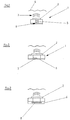
- Fig. 1 schematically a device 1 with an ultrasonic transducer 2 is shown, the sound waves 3 emanating to a liquid surface 4.
- the liquid surface 4 forms an interface between the medium to be investigated, in particular oil, and an overlying gas, in particular air.
- the ultrasonic transducer 2 is formed by a piezoceramic, which can also serve as transmitter and receiver.
- the ultrasound transducer 2 is arranged at a distance from a bottom of the liquid container, in particular the oil container, so that sound waves 5 are radiated from the back of the ultrasound transducer 2 and reflected at a rear reflector 6, in particular at the bottom of the container.
- the ultrasonic transducer 2 is arranged on a flange in which a channel or a depression is provided, in which the sound waves 5 radiated on the back run and which in this way forms a defined reference distance.
- the ultrasonic transducer 2 is directly flowed around by the liquid, in particular here by the oil, so that the implemented reference path with the sound waves 5 is filled with the medium oil.
- the ultrasonic transducer 2 emits a time-limited ultrasonic wave packet.
- This wave packet is reflected at the oil-air interface and is received again after a running time t on the same ultrasonic transducer.
- the running distance is determined from the runtime of the wave packet.
- the running distance is exactly twice the distance between the ultrasonic transducer and the interface between oil and air. In the optimal case, this distance is equal to the level in the liquid container, provided that the ultrasonic transducer mounted on the container bottom, the transmitting surface is equal to the bottom surface and the reflection surface is plane-parallel to the transmitting surface.
- the knowledge of the speed of sound in the measuring medium is necessary. Among other things, this has a dependence on the measuring medium and the temperature.
- the reference distance is therefore used to compensate for this influence or to calculate the speed of sound.
- the sound velocity which is not exactly known is determined from the transit time of the signal reflected at this reference surface and the known distance of the reflection surface or rear-side reflector 6 from the ultrasound transducer 2.
- Fig. 2 is shown as a special feature of the device 1, an additional edge 7 in the rear reflector 6. This results in that the echo signal of the rear reflector receives a unique identifier and in this way can be clearly distinguished from the signal reflected from the liquid surface.
- a layer stack 8 In Fig. 3 arranged in the rear reflector 6, a layer stack 8. This layer stack or layer packet generates a phase jump in the reference signal, which also ensures unambiguity with respect to the distinction of the reference signal from the echo signal of the liquid surface.
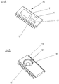
- the ultrasonic transducer 2 is shown, which is integrated here in the housing 10 with the other components.
- This housing is designed as a total sensor element and has in addition to the ultrasonic transducer 2 an ASIC with temperature detection 14 and a plurality of passive components 15 such as capacitors, resistors, diodes, transistors, varistors and / or coils.
- Fig. 5 the housing 10 is shown again, in which case the recess 11 is shown for receiving the ultrasonic transducer 2.
- the recess 11 is comparatively large and adapted to the shape of the ultrasonic transducer 2 to be accommodated.
- a support element in the form of a ring 12 is provided, on which the ultrasonic transducer is positioned, and further, a lower end layer is provided, which only a relatively small opening 13 releases, through which only a smaller portion of the sound waves emitted to the back down passes to the rear reflector.
- the size of this recess is designed so that a signal with the desired energy is emitted downwards.
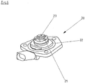
- a flange group 20 is shown, which can be mounted on the underside of the liquid container, in particular the oil pan, and is due to an opening in the liquid container in direct contact with the liquid, in particular the engine oil is.
- An axial rubber seal 22 seals the system to the outside.
- the flange group 20 has a mounting surface 23 for the housing 10 with the ultrasonic transducer 2 on.
- a recess which is designed here as a channel 21, is provided.
- the width of this channel 21 is adapted to the size of the lower opening 13 in the housing 10.
Landscapes
- Physics & Mathematics (AREA)
- Acoustics & Sound (AREA)
- Electromagnetism (AREA)
- Thermal Sciences (AREA)
- Fluid Mechanics (AREA)
- General Physics & Mathematics (AREA)
- Measurement Of Levels Of Liquids Or Fluent Solid Materials (AREA)
- Transducers For Ultrasonic Waves (AREA)
- Measurement Of Velocity Or Position Using Acoustic Or Ultrasonic Waves (AREA)
Description
- Die Erfindung betrifft eine Vorrichtung aufweisend einen Behälter und einen mit einem Ultraschallwandler zum Messen des Füllstandes einer Flüssigkeit nach dem Ultraschall-Echo-Prinzip in dem Behälter mit den Merkmalen des Oberbegriffs des Patentanspruchs 1.
- Eine gattungsgemäße Vorrichtung ist aus der
US 5,568,449 A bekannt. - Nach der
US 4,984,449 A oder derUS 5,568,449 A sind Flüssigkeitsfüllstandsmesssysteme bekannt, die rohrförmige Ultraschallmesskörper aufweisen, die in vertikaler Richtung von oben in einen Flüssigkeitsbehälter eingesetzt werden. Innerhalb des Messkörpers ist ein Ultraschallwandler im Abstand zum unteren Ende des Messkörpers angeordnet. Der Ultraschallwandler sendet vertikal nach oben und vertikal nach unten Ultraschallimpulse aus, mit denen die Füllstandshöhe der Flüssigkeit im Behälter ermittelt wird. Gleichzeitig erfolgt eine Referenzmessung in Richtung der Flüssigkeitsoberfläche, wobei oberhalb des Ultraschallwandlers in vorgegebenen Abständen Kalibrierreflektoren angeordnet sind. - Aus der
DE 103 31 566 A1 ist eine Vorrichtung zum Messen des Füllstandes einer Flüssigkeit nach dem Ultraschall-Echo-Prinzip in einem Behälter mit einem Ultraschallwandler bekannt, wobei der Ultraschallwandler mit Abstand zu einer reflektierenden Fläche angeordnet ist und einerseits zur Abstrahlung zur Flüssigkeitsoberfläche und andererseits zu der reflektierenden Fläche ausgelegt ist, wobei die Vorrichtung am Boden eines Behälters angeordnet ist. - Eine weitere Vorrichtung ist beispielsweise aus der
EP 1 460 396 bekannt. Bei dieser Vorrichtung erfolgt die Auswertung dadurch, dass infolge von Mehrfachreflexionen an der Flüssigkeitsoberfläche und im Bereich des Behälterbodens in Peaks gesplittete Echosignale erfasst werden und dass die aus dem bestimmten Abstand resultierenden zeitlichen Abstände der Peaks zur Bestimmung der Schallgeschwindigkeit in der Flüssigkeit ausgewertet werden. - Nach der
DE 2 59 809 A1 ist eine Einrichtung zur Füllstandsmessung in einem Kraftstofftank bekannt, die mit einem Ultraschallwandler ausgerüstet ist. Der Ultraschallwandler weist jeweils einen Messabschnitt und einen Referenzabschnitt auf, wobei mittels des Messabschnittes der Füllstand im Kraftstofftank und mit Hilfe des Referenzabschnittes eine Referenzmessung durchgeführt wird. Beide Messungen erfolgen von der Oberseite des Ultraschallwandlers aus in Richtung der Oberfläche der Flüssigkeit. Die zur Referenzmessung benötigten Reflektionsflächen werden mit Hilfe von Gehäuseabschnitten ausgebildet, welche über die Referenzabschnitte des Ultraschallwandlers vorstehen. - Die
US 5,379,658 A offenbart ein Füllstandsmessgerät mit einem Schallwandler, der über eine Flanschanordnung in einer Öffnung an der Unterseite eines Tanks abdichtend montiert ist. Der Schallwandler ist mit seiner Sensorfläche akustisch mit der Flüssigkeit gekoppelt, wobei der Schallwandler nur Schallwellen zur Bestimmung der Füllstandshöhe in Richtung der Flüssigkeitsoberfläche aussendet. - Der Erfindung liegt die Aufgabe zugrunde, eine Vorrichtung der eingangs genannten Art zu schaffen, die besonders einfach aufgebaut ist und eine besonders zuverlässige Messung nach dem Ultraschall-Echo-Prinzip erlaubt.
- Die Lösung dieser Aufgabe erfolgt mit einer Vorrichtung mit den Merkmalen des Patentanspruchs 1. Vorteilhafte Weiterbildungen der Erfindung sind in den Unteransprüchen angegeben.
- Bei einer Vorrichtung zum Messen des Füllstands einer Flüssigkeit nach dem Ultraschall-Echo-Prinzip in einem Behälter mit einem Ultraschallwandler, bei dem der Ultraschallwandler mit Abstand zu einer im Bodenbereich des Behälters angeordneten reflektierenden Fläche angeordnet ist und einerseits zur Abstrahlung zu der Flüssigkeitsoberfläche und andererseits zu der reflektierenden Fläche ausgelegt ist, ist es vorgesehen, dass unterhalb des Ultraschallwandlers eine Vertiefung im Boden der Vorrichtung angeordnet ist. Der Boden des Behälters, genauer der Boden innerhalb dieser Vertiefung, dient dann als reflektierende Fläche oder als Reflektor. Die Vertiefung definiert eine Referenzstrecke. Auf diese Weise ist es möglich, eine feste Referenzstrecke zur Vergleichsmessung heranzuziehen und die Referenzstrecke unabhängig von der eigentlichen Messstrecke auszubilden und auf diese Weise zu erreichen, dass die beiden Messungen sich gegenseitig möglichst wenig beeinflussen. Nach der Erfindung ist die Vorrichtung als Flansch zur Montage an die Unterseite eines Flüssigkeitsbehälters, insbesondere einer Ölwanne, ausgebildet. Der Flansch besteht bevorzugt aus einer Flanschgruppe mit einem Dichtungsring, einer Referenzstrecke und einem Ultraschallwandler einschließlich der Schaltungstechnik, die in einem integrierten Schaltkreis angeordnet ist.
- Unter einem Ultraschallwandler wird jede Vorrichtung zur Umwandlung eines Signals in eine Ultraschallschwingung und umgekehrt verstanden. Der Ultraschallwandler wird bevorzugt als Sender und als Empfänger verwendet. Es ist jedoch auch denkbar, den erfindungsgemäßen Ultraschallwandler nur als Sender zu verwenden und einen baulich davon getrennten Empfänger zu verwenden. Der Ultraschallwandler ist bevorzugt als piezoelektrischer Wandler ausgebildet. Insbesondere werden hierfür piezoelektrische Keramiken oder auch piezoelektrische Kristalle verwendet. In einer anderen bevorzugten Ausgestaltung der Erfindung sind der Sender und der Empfänger und bevorzugt auch eine Auswerteeinheit in einem Gehäuse, in dem auch ein integrierter Schaltkreis, insbesondere im vorliegenden Fall ein ASIC, angeordnet ist. Das Gehäuse ist dabei bevorzugt aus Plastikmaterial oder einem Polymer ausgebildet.
- In einer anderen Ausgestaltung der Erfindung ist der Sender in einem Gehäuse angeordnet, das eine Ausnehmung mit Öffnungen nach oben und unten aufweist. In einer bevorzugten Ausgestaltung der Erfindung sendet die Vorrichtung den Ultraschall mit einer größeren Leistung nach oben als nach unten. Hierzu werden bevorzugt Gehäuseanpassungen vorgenommen, insbesondere werden in dem Gehäuse nach oben und nach unten unterschiedlich große Öffnungen vorgesehen. Denkbar sind auch andere Anpassungen, wie beispielsweise die Einbauart des Ultraschallwandlers im Gehäuse oder die Verwendung von Dämpfungselementen. Günstigerweise ist dazu in dem Gehäuse die untere bzw. die zur Referenzstrecke gerichtete Öffnung kleiner als die obere bzw. die zur Flüssigkeitsoberfläche gerichtete Öffnung ausgebildet. In dem Gehäuse ist eine Ausnehmung vorgesehen, in die bevorzugt von oben herein der Ultraschallwandler bzw. insbesondere ein Piezokristall formschlüssig eingelegt wird. Alternativ kann der Ultraschallwandler auf einen Metallrahmen, insbesondere ein Stanzgitter oder "Leadframe" montiert und anschließend mit einem Plastikmaterial umhüllt oder verkapselt werden. Zur besseren Auskopplung des Ultraschalls kann hierbei die Oberfläche des Ultraschallwandlerelementes von dem Gehäusematerial ausgeschlossen werden. Hierzu wird eine Herstellungstechnologie verwendet, bei der die gesamte aktive Oberfläche des Ultraschallwandlers oder zumindest Teilbereiche davon vom Gehäusematerial freigehalten werden. Die untere wie auch die obere Öffnung sind bevorzugt entsprechend der abzustrahlenden Leistung dimensioniert, wobei die obere, zur Flüssigkeitsoberfläche gerichtete Öffnung bevorzugt die gleiche Größe wie der Ultraschallwandler bzw. dessen aktive Oberfläche aufweist, um eine maximale Sendeleistung zu erreichen. In dem Bauteil selbst ist bevorzugt außerdem eine Einrichtung zur Temperaturerfassung vorgesehen. Diese ist bevorzugt als ASIC mit Temperaturerfassung ausgebildet. Weiterhin sind passive elektrische Komponenten, wie Kondensatoren, Widerstände, Dioden, Transistoren, Varistoren und/oder Spulen in dem Gehäuse angeordnet.
- Der integrierte Schaltkreis, insbesondere der ASIC, dient außerdem zur Signalansteuerung und Verarbeitung der empfangenen Signale. Das Gehäuse, das auch als Multichipmodul bezeichnet werden kann, ist zudem bevorzugt beschichtet, um eine Flüssigkeitsbeständigkeit, insbesondere eine Ölbeständigkeit, des Sensorelementes oder des Ultraschallwandlers zu gewährleisten.
- Erfindungsgemäß ist unterhalb des Ultraschallwandlers eine Vertiefung im Boden der Vorrichtung vorgesehen. Dadurch wird ein Echo auf den Empfänger zurückgeleitet und eine Reflexion in andere Bereiche, insbesondere in solche Bereiche, in denen eine Unterscheidung von der von der Oberfläche reflektierten Strahlung nur schwer möglich ist, verhindert. Die Vertiefung ist bevorzugt entsprechend der unteren Abstrahlöffnung im Gehäuse dimensioniert. Die Vertiefung ist erfindungsgemäß kanalartig ausgebildet. Dadurch kann in der Vertiefung ein Durchfluss des zu überprüfenden Mediums erfolgen. Die Vertiefung ist bevorzugt unterhalb einer Montagefläche für das Gehäuse angeordnet. In einer anderen bevorzugten Ausgestaltung der Erfindung ist am Boden der Vorrichtung, insbesondere in der Vertiefung, eine Einrichtung zur Beeinflussung des Ultraschallsignals vorgesehen. Auf diese Weise wird eine Kennung in das Echo eingeprägt, so dass auf diese Weise eine sichere Unterscheidung zwischen dem von der Flüssigkeitsoberfläche reflektierten Signal und dem vom Boden reflektierten Signal möglich ist und die Auswerteelektronik daher die reflektierten Signale zuverlässig unterscheiden kann. In einer bevorzugten Ausgestaltung ist die Einrichtung zur Beeinflussung des Ultraschallsignals als eine Kante ausgebildet. In einer anderen bevorzugten Ausgestaltung ist die Einrichtung zur Beeinflussung des Ultraschallsignals als Schichtstapel ausgebildet. Dadurch kann ein Phasensprung im Referenzsignal erzeugt werden, der eine Eindeutigkeit des Signals bewirkt. Eine andere Möglichkeit der Ausgestaltung der Einrichtung zur Beeinflussung des Ultraschallsignals ist ein zweistufiger und/oder geteilter Referenzreflektor. Insgesamt ergeben sich dann Interferenzeffekte beider Teilechos bei der Überlagerung zu einem charakteristischen Signalbild in Referenzecho.
- Alternativ können die Echos vom Referenzreflektor und von der Flüssigkeitsoberfläche auch über die unterschiedlichen Laufzeiten unterschieden werden.
- Nachfolgend wird die Erfindung anhand eines in der Zeichnung dargestellten Ausführungsbeispiels weiter erläutert. Im Einzelnen zeigen die schematischen Darstellungen in:
- Fig. 1:
- eine schematische Darstellung des Prinzips der erfindungsgemäßen Vorrichtung;
- Fig. 2:
- eine schematische Darstellung einer besonderen Ausführung der erfindungsgemäßen Vorrichtung;
- Fig. 3:
- eine alternative Ausführungsform der erfindungsgemäßen Vorrichtung zu
Figur 2 ; - Fig. 4:
- eine schematische Darstellung eines Gehäuses der erfindungsgemäßen Vorrichtung mit mehreren darin aufgenommenen Komponenten;
- Fig. 5:
- eine perspektivische Ansicht eines speziell angepassten Gehäuses für die erfindungsgemäße Vorrichtung; und
- Fig. 6:
- einen Flansch zur Ausbildung der erfindungsgemäßen Vorrichtung und zur Aufnahme eines Gehäuses beispielsweise gemäß der
Figuren 4 oder 5 . - In
Fig. 1 ist schematisch eine Vorrichtung 1 mit einem Ultraschallwandler 2 dargestellt, der Schallwellen 3 zu einer Flüssigkeitsoberfläche 4 ausstrahlt. Die Flüssigkeitsoberfläche 4 bildet eine Grenzschicht zwischen dem zu untersuchenden Medium, insbesondere Öl, und einem darüberliegenden Gas, insbesondere Luft. An dieser Grenzschicht erfolgt eine Reflexion der Schallwellen 3, so dass die reflektierte Schallwelle 3 als Echo zurück auf den Ultraschallwandler geworfen wird. Der Ultraschallwandler 2 wird von einer Piezokeramik gebildet, die gleichfalls als Sender und Empfänger dienen kann. Der Ultraschallwandler 2 ist mit Abstand zu einem Boden des Flüssigkeitbehälters, insbesondere des Ölbehälters, angeordnet, so dass von dem Ultraschallwandler 2 auch Schallwellen 5 rückseitig abgestrahlt werden und an einem rückseitigen Reflektor 6, insbesondere am Boden des Behälters, reflektiert werden. In derFig. 1 ist bereits angedeutet, dass der Ultraschallwandler 2 auf einem Flansch angeordnet ist, in dem ein Kanal oder eine Vertiefung vorgesehen ist, in der die rückseitig abgestrahlten Schallwellen 5 verlaufen und der auf diese Weise eine definierte Referenzstrecke bildet. Der Ultraschallwandler 2 ist direkt von der Flüssigkeit, insbesondere hier vom Öl, umströmt, so dass auch die implementierte Referenzstrecke mit den Schallwellen 5 mit dem Medium Öl gefüllt ist. Der Ultraschallwandler 2 sendet ein zeitlich begrenztes Ultraschallwellenpaket aus. Dieses Wellenpaket wird an der Grenzfläche Öl-Luft reflektiert und wird nach einer Laufzeit t wieder am selben Ultraschallwandler empfangen. Aus der Laufzeit des Wellenpaketes wird die Laufstrecke ermittelt. Die Laufstrecke ist genau doppelt so groß wie die Entfernung zwischen dem Ultraschallwandler und der Grenzfläche zwischen Öl und Luft. Im optimalen Fall ist diese Entfernung gleich dem Füllstand im Flüssigkeitsbehälter, sofern der Ultraschallwandler am Behälterboden montiert, die Sendefläche gleich der Bodenfläche sowie die Reflektionsfläche planparallel zur Sendefläche ist. Für diese Berechnung der Laufstrecke ist die Kenntnis der Schallgeschwindigkeit im Messmedium erforderlich. Diese weist unter anderem eine Abhängigkeit von dem Messmedium und der Temperatur auf. Die Referenzstrecke dient daher dazu, diesen Einfluss zu kompensieren bzw. die Schallgeschwindigkeit zu berechnen. Die nicht genau bekannte Schallgeschwindigkeit wird aus der Laufzeit des an dieser Referenzfläche reflektierten Signals und dem bekannten Abstand der Reflexionsfläche bzw. des rückseitigen Reflektors 6 zum Ultraschallwandler 2 ermittelt. - In
Fig. 2 ist als Besonderheit der Vorrichtung 1 eine zusätzliche Kante 7 im rückseitigen Reflektor 6 dargestellt. Diese führt dazu, dass das Echosignal des rückseitigen Reflektors eine eindeutige Kennung erhält und auf diese Weise eindeutig von dem von der Flüssigkeitsoberfläche reflektierten Signal unterschieden werden kann. - Alternativ ist dazu in
Fig. 3 im rückseitigen Reflektor 6 ein Schichtstapel 8 angeordnet. Dieser Schichtstapel oder Schichtpaket erzeugt einen Phasensprung im Referenzsignal, der ebenfalls eine Eindeutigkeit hinsichtlich der Unterscheidung des Referenzsignals vom Echosignal der Flüssigkeitsoberfläche gewährleistet. - In
Fig. 4 ist der Ultraschallwandler 2 dargestellt, der hier in das Gehäuse 10 mit den weiteren Komponenten integriert ist. Dieses Gehäuse ist als Gesamtsensorelement ausgebildet und weist neben dem Ultraschallwandler 2 einen ASIC mit Temperaturerfassung 14 und mehrere passive Komponenten 15 wie beispielsweise Kondensatoren, Widerstände, Dioden, Transistoren, Varistoren und/oder Spulen auf. - In
Fig. 5 ist das Gehäuse 10 noch einmal dargestellt, wobei hier die Ausnehmung 11 zur Aufnahme des Ultraschallwandlers 2 dargestellt ist. Auf der Oberseite ist die Ausnehmung 11 vergleichsweise groß und an die Form des aufzunehmenden Ultraschallwandlers 2 angepasst. Im unteren Bereich ist ein Auflageelement in Form eines Ringes 12 vorgesehen, auf dem der Ultraschallwandler positioniert ist, und weiterhin ist eine untere Abschlussschicht vorgesehen, die nur eine vergleichsweise kleine Öffnung 13 freigibt, durch die nur ein kleinerer Anteil der zur Rückseite abgestrahlten Schallwellen nach unten zum rückseitigen Reflektor hindurchtritt. Die Größe dieser Ausnehmung ist derart ausgelegt, dass ein Signal mit der gewünschten Energie nach unten abgestrahlt wird. - In
Fig. 6 ist eine Flanschgruppe 20 dargestellt, die an die Unterseite des Flüssigkeitsbehälters, insbesondere der Ölwanne, montiert werden kann und sich aufgrund einer Öffnung im Flüssigkeitsbehälter in direktem Kontakt mit der Flüssigkeit, insbesondere dem Motoröl, befindet. Eine axiale Gummidichtung 22 schließt das System nach außen dicht ab. Die Flanschgruppe 20 weist eine Montagefläche 23 für das Gehäuse 10 mit dem Ultraschallwandler 2 auf. In der Montagefläche 23 ist eine Vertiefung, die hier als Kanal 21 ausgebildet ist, vorgesehen. Die Breite dieses Kanals 21 ist an die Größe der unteren Öffnung 13 im Gehäuse 10 angepasst.
Claims (11)
- Vorrichtung aufweisend einen Behälter und einen Ultraschallwandler (2) zum Messen des Füllstandes einer Flüssigkeit nach dem Ultraschall-Echo-Prinzip in dem Behälter, wobei der Ultraschallwandler (2) in einem Gehäuse (10) mit Abstand zu einer reflektierenden Fläche (6) angeordnet ist und einerseits zur Abstrahlung zur Flüssigkeitsoberfläche und andererseits zu der reflektierenden Fläche (6) ausgelegt ist,
wobei die reflektierende Fläche (6) unterhalb des Ultraschallwandlers (2) im Boden des Behälters für eine Referenzmessung zwischen dem Ultraschallwandler (2) und der reflektierenden Fläche (6) angeordnet ist,
wobei der Ultraschallwandler (2) mit einer Flanschgruppe (20) mit einem Dichtungsring in einer Öffnung an der Unterseite des Behälters montiert ist. dadurch gekennzeichnet,
dass die reflektierende Fläche (6) eine kanalartige reflektierende Vertiefung (21) im Boden des Behälters aufweist ist, so dass ein Durchfluss der Flüssigkeit erfolgt,
dass die Flanschgruppe (20) eine Montagefläche (23) für das Gehäuse (10) des Ultraschallwandlers (2) aufweist und
dass die kanalartige reflektierende Vertiefung (21) unterhalb der Montagefläche (23) angeordnet ist. - Vorrichtung nach Anspruch 1, dadurch gekennzeichnet, dass der Ultraschallwandler (2) auch als Empfänger dient.
- Vorrichtung nach einem der Ansprüche 1 oder 2, dadurch gekennzeichnet, dass der Ultraschallwandler (2), ein Empfänger und eine Auswerteeinheit in einem Gehäuse integriert sind.
- Vorrichtung nach einem der vorhergehenden Ansprüche, dadurch gekennzeichnet, dass elektronische Komponenten, insbesondere ein ASIC, in dem Gehäuse integriert sind.
- Vorrichtung nach einem der vorhergehenden Ansprüche, dadurch gekennzeichnet, dass das Gehäuse eine Öffnung nach oben und eine Öffnung nach unten zur Aufnahme des Ultraschallwandlers (2) aufweist.
- Vorrichtung nach Anspruch 5, dadurch gekennzeichnet, dass die untere Öffnung (13) und die obere Öffnung (11) unterschiedlich groß ausgebildet sind.
- Vorrichtung nach einem der Ansprüche 5 oder 6, dadurch gekennzeichnet, dass die obere Öffnung (11) und die untere Öffnung (13) entsprechend der abzustrahlenden Leistung dimensioniert sind.
- Vorrichtung nach einem der Ansprüche 4 bis 7, dadurch gekennzeichnet, dass das Gehäuse eine Einrichtung zur Temperaturerfassung (14) aufweist.
- Vorrichtung nach einem der vorhergehenden Ansprüche, dadurch gekennzeichnet, dass am Boden der Vorrichtung, insbesondere in der Vertiefung (21), eine Einrichtung zur Beeinflussung des Ultraschallsignals vorgesehen ist.
- Vorrichtung nach Anspruch 9, dadurch gekennzeichnet, dass die Einrichtung zur Beeinflussung des Ultraschallsignals als Kante (7) ausgebildet ist.
- Vorrichtung nach Anspruch 9, dadurch gekennzeichnet, dass die Einrichtung zur Beeinflussung des Ultraschallsignals als Schichtstapel (8) ausgebildet ist.
Applications Claiming Priority (2)
| Application Number | Priority Date | Filing Date | Title |
|---|---|---|---|
| DE102005012566A DE102005012566A1 (de) | 2005-03-18 | 2005-03-18 | Vorrichtung zum Messen des Füllstandes einer Flüssigkeit in einem Behälter mit einem Ultraschallwandler |
| PCT/DE2006/000446 WO2006097076A1 (de) | 2005-03-18 | 2006-03-14 | Vorrichtung zum messen des füllstandes einer flüssigkeit in einem behälter mit einem ultraschallwandler |
Publications (2)
| Publication Number | Publication Date |
|---|---|
| EP1859236A1 EP1859236A1 (de) | 2007-11-28 |
| EP1859236B1 true EP1859236B1 (de) | 2019-02-20 |
Family
ID=36477561
Family Applications (1)
| Application Number | Title | Priority Date | Filing Date |
|---|---|---|---|
| EP06722603.5A Expired - Lifetime EP1859236B1 (de) | 2005-03-18 | 2006-03-14 | Vorrichtung zum messen des füllstandes einer flüssigkeit in einem behälter mit einem ultraschallwandler |
Country Status (5)
| Country | Link |
|---|---|
| EP (1) | EP1859236B1 (de) |
| JP (1) | JP4728388B2 (de) |
| KR (1) | KR101304373B1 (de) |
| DE (1) | DE102005012566A1 (de) |
| WO (1) | WO2006097076A1 (de) |
Families Citing this family (4)
| Publication number | Priority date | Publication date | Assignee | Title |
|---|---|---|---|---|
| KR101724875B1 (ko) | 2015-07-20 | 2017-04-18 | 현대자동차주식회사 | 엔진오일레벨센서 미적용 엔진오일레벨 경고방법 및 이를 위한 엔진오일레벨 경고시스템 |
| CN110160603B (zh) * | 2018-02-11 | 2024-01-26 | 宁波方太厨具有限公司 | 一种吸油烟机的油杯液位测量装置 |
| DE102018006130B3 (de) * | 2018-08-03 | 2019-08-08 | Pepperl + Fuchs Gmbh | 1D-Ultraschallwandler-Einheit zur Gefahrenerkennung für ein Fahrzeug |
| DE102020200771B4 (de) | 2020-01-23 | 2023-03-30 | Vitesco Technologies Germany Gmbh | Fluidsensorvorrichtung zum Erfassen des Füllstands und/oder der Qualität eines Fluids und Verfahren zum Herstellen derselben |
Family Cites Families (10)
| Publication number | Priority date | Publication date | Assignee | Title |
|---|---|---|---|---|
| US4656384A (en) * | 1984-10-25 | 1987-04-07 | Siemens Aktiengesellschaft | Ultrasonic detection sensor in hybrid structure with appertaining electronic circuit |
| US4984449A (en) | 1989-07-03 | 1991-01-15 | Caldwell System Corp. | Ultrasonic liquid level monitoring system |
| US5379658A (en) * | 1992-11-16 | 1995-01-10 | Simmonds Precision Products, Inc. | Intrusive acoustic sensor mounting arrangement |
| US5568449A (en) | 1994-09-02 | 1996-10-22 | U.S. Test, Inc. | Methods and apparatus for use in ultrasonic ranging |
| JP2000241232A (ja) * | 1999-02-19 | 2000-09-08 | Tokimec Inc | 界面計測方法及びマイクロ波界面計 |
| DE10130540A1 (de) * | 2001-06-20 | 2003-01-09 | Turck Werner Kg | Füllstandsmessgerät zum Ermitteln des Flüssigkeitspegels in einem Behälter |
| FR2834061B1 (fr) | 2001-12-21 | 2004-07-09 | Marwal Systems | Jauge de niveau |
| US6993967B2 (en) | 2002-07-12 | 2006-02-07 | Ti Group Automotive Systems, L.L.C. | Fluid level sensor |
| DE10309861B4 (de) | 2003-03-06 | 2006-05-04 | Robert Seuffer Gmbh & Co. Kg | Verfahren und Vorrichtung zur Bestimmung wenigstens einer chemischen oder physikalischen Eigenschaft einer Flüssigkeit bei Füllstandsmessung in einem Behälter |
| DE10350084B4 (de) * | 2003-10-27 | 2016-05-19 | Continental Automotive Gmbh | Sensoreinrichtung zum Erfassen eines Füllstands und Verfahren zum Betreiben der Sensoreinrichtung |
-
2005
- 2005-03-18 DE DE102005012566A patent/DE102005012566A1/de not_active Withdrawn
-
2006
- 2006-03-14 EP EP06722603.5A patent/EP1859236B1/de not_active Expired - Lifetime
- 2006-03-14 WO PCT/DE2006/000446 patent/WO2006097076A1/de not_active Ceased
- 2006-03-14 KR KR1020077023851A patent/KR101304373B1/ko not_active Expired - Fee Related
- 2006-03-14 JP JP2008501152A patent/JP4728388B2/ja not_active Expired - Lifetime
Non-Patent Citations (1)
| Title |
|---|
| None * |
Also Published As
| Publication number | Publication date |
|---|---|
| WO2006097076A1 (de) | 2006-09-21 |
| JP4728388B2 (ja) | 2011-07-20 |
| KR20080007326A (ko) | 2008-01-18 |
| JP2008533474A (ja) | 2008-08-21 |
| DE102005012566A1 (de) | 2006-09-21 |
| KR101304373B1 (ko) | 2013-09-11 |
| EP1859236A1 (de) | 2007-11-28 |
Similar Documents
| Publication | Publication Date | Title |
|---|---|---|
| DE4025326C2 (de) | Verfahren und Vorrichtung zum Messen der Flüssigkeitshöhe einer bewegten Flüssigkeit in einem Behälter | |
| DE4307635A1 (de) | ||
| DE112007000456T5 (de) | Eingetauchter Kraftstofffüllstandssensor | |
| DE102012005281A1 (de) | Fördereinheit mit Füllstandsensor für ein flüssiges Additiv | |
| DE112014004566T5 (de) | Verringerung belüftungsbedingter Störungen in einem Ultraschallerfassungssystem für ein Fluid | |
| DE102009036888B4 (de) | Dämpfungsbecher, Ölstandsmesseinrichtung mit einem solchen sowie Kraftfahrzeug mit einer solchen Ölstandsmesseinrichtung | |
| DE4306193B4 (de) | Füllstandssensor | |
| EP3756000A1 (de) | Vorrichtung zur qualitätsbestimmung, tankvorrichtung | |
| EP2681519B1 (de) | Anordnung und verfahren zur ermittlung einer konzentration eines bestandteils eines fluidgemisches | |
| DE102005043263C5 (de) | Vorrichtung zum Erfassen eines Füllstands eines Fluids in einem Behälter | |
| WO2012123344A1 (de) | Verfahren zur kalibrierung eines ultraschall - füllstandsensors | |
| DE3025363A1 (de) | Gabelstapler mit einer ultraschallmessvorrichtung fuer die gabelhoehe | |
| EP3652529A1 (de) | Vorrichtung zum messen der konzentration eines reduktionsmittels | |
| EP1859236B1 (de) | Vorrichtung zum messen des füllstandes einer flüssigkeit in einem behälter mit einem ultraschallwandler | |
| DE102012002011A1 (de) | Vorrichtung zur Messung eines Füllstands einer Flüssigkeit und ölgeschmierter Motor | |
| DE19637978B4 (de) | Fluidmengenmeßsystem | |
| WO2014009165A1 (de) | Verfahren und vorrichtung zum bestimmen einer höhe eines fluidniveaus in einem fluidbehälter | |
| EP1460396B1 (de) | Verfahren und Vorrichtung zur Ultraschall-Füllstandsmessung einer Flüssigkeit in einem Behälter | |
| WO2007137647A1 (de) | Bestimmung der federhöhe einer luftfeder nach einem impuls-laufzeitmessverfahren | |
| EP1039272A2 (de) | Niveauabhängige Steuerung von Pumpen | |
| DE102006045654B3 (de) | Kombinationssensor und Verfahren zur Bestimmung von Zustand und Füllstand einer Füssigkeit in einem Behälter | |
| EP3737941B1 (de) | Ultraschallsensor mit ultraschallreflektor sowie fluidtank mit einem derartigen ultraschallsensor | |
| DE102018202209B3 (de) | Vorrichtung zum Bestimmen einer Höhe und/oder Qualität eines Fluids in einem Fluidbehälter | |
| DE102009023211A1 (de) | Dämpfungsbecher | |
| DE102018105267B3 (de) | Dämpfungselement für einen Ultraschallsensor |
Legal Events
| Date | Code | Title | Description |
|---|---|---|---|
| PUAI | Public reference made under article 153(3) epc to a published international application that has entered the european phase |
Free format text: ORIGINAL CODE: 0009012 |
|
| 17P | Request for examination filed |
Effective date: 20070825 |
|
| AK | Designated contracting states |
Kind code of ref document: A1 Designated state(s): AT BE BG CH CY CZ DE DK EE ES FI FR GB GR HU IE IS IT LI LT LU LV MC NL PL PT RO SE SI SK TR |
|
| RIN1 | Information on inventor provided before grant (corrected) |
Inventor name: DOBRINSKI, HEIKO Inventor name: BUHRDORF, ANDREAS Inventor name: KUECK, THOMAS |
|
| DAX | Request for extension of the european patent (deleted) | ||
| 17Q | First examination report despatched |
Effective date: 20141016 |
|
| RAP1 | Party data changed (applicant data changed or rights of an application transferred) |
Owner name: HELLA GMBH & CO. KGAA |
|
| STAA | Information on the status of an ep patent application or granted ep patent |
Free format text: STATUS: EXAMINATION IS IN PROGRESS |
|
| GRAP | Despatch of communication of intention to grant a patent |
Free format text: ORIGINAL CODE: EPIDOSNIGR1 |
|
| STAA | Information on the status of an ep patent application or granted ep patent |
Free format text: STATUS: GRANT OF PATENT IS INTENDED |
|
| INTG | Intention to grant announced |
Effective date: 20181005 |
|
| GRAS | Grant fee paid |
Free format text: ORIGINAL CODE: EPIDOSNIGR3 |
|
| GRAA | (expected) grant |
Free format text: ORIGINAL CODE: 0009210 |
|
| STAA | Information on the status of an ep patent application or granted ep patent |
Free format text: STATUS: THE PATENT HAS BEEN GRANTED |
|
| AK | Designated contracting states |
Kind code of ref document: B1 Designated state(s): AT BE BG CH CY CZ DE DK EE ES FI FR GB GR HU IE IS IT LI LT LU LV MC NL PL PT RO SE SI SK TR |
|
| REG | Reference to a national code |
Ref country code: GB Ref legal event code: FG4D Free format text: NOT ENGLISH |
|
| REG | Reference to a national code |
Ref country code: CH Ref legal event code: EP |
|
| REG | Reference to a national code |
Ref country code: DE Ref legal event code: R096 Ref document number: 502006016179 Country of ref document: DE |
|
| REG | Reference to a national code |
Ref country code: AT Ref legal event code: REF Ref document number: 1098806 Country of ref document: AT Kind code of ref document: T Effective date: 20190315 |
|
| REG | Reference to a national code |
Ref country code: IE Ref legal event code: FG4D Free format text: LANGUAGE OF EP DOCUMENT: GERMAN |
|
| REG | Reference to a national code |
Ref country code: LT Ref legal event code: MG4D |
|
| REG | Reference to a national code |
Ref country code: NL Ref legal event code: MP Effective date: 20190220 |
|
| PG25 | Lapsed in a contracting state [announced via postgrant information from national office to epo] |
Ref country code: LT Free format text: LAPSE BECAUSE OF FAILURE TO SUBMIT A TRANSLATION OF THE DESCRIPTION OR TO PAY THE FEE WITHIN THE PRESCRIBED TIME-LIMIT Effective date: 20190220 Ref country code: SE Free format text: LAPSE BECAUSE OF FAILURE TO SUBMIT A TRANSLATION OF THE DESCRIPTION OR TO PAY THE FEE WITHIN THE PRESCRIBED TIME-LIMIT Effective date: 20190220 Ref country code: PT Free format text: LAPSE BECAUSE OF FAILURE TO SUBMIT A TRANSLATION OF THE DESCRIPTION OR TO PAY THE FEE WITHIN THE PRESCRIBED TIME-LIMIT Effective date: 20190620 Ref country code: FI Free format text: LAPSE BECAUSE OF FAILURE TO SUBMIT A TRANSLATION OF THE DESCRIPTION OR TO PAY THE FEE WITHIN THE PRESCRIBED TIME-LIMIT Effective date: 20190220 |
|
| PG25 | Lapsed in a contracting state [announced via postgrant information from national office to epo] |
Ref country code: NL Free format text: LAPSE BECAUSE OF FAILURE TO SUBMIT A TRANSLATION OF THE DESCRIPTION OR TO PAY THE FEE WITHIN THE PRESCRIBED TIME-LIMIT Effective date: 20190220 Ref country code: GR Free format text: LAPSE BECAUSE OF FAILURE TO SUBMIT A TRANSLATION OF THE DESCRIPTION OR TO PAY THE FEE WITHIN THE PRESCRIBED TIME-LIMIT Effective date: 20190521 Ref country code: LV Free format text: LAPSE BECAUSE OF FAILURE TO SUBMIT A TRANSLATION OF THE DESCRIPTION OR TO PAY THE FEE WITHIN THE PRESCRIBED TIME-LIMIT Effective date: 20190220 Ref country code: BG Free format text: LAPSE BECAUSE OF FAILURE TO SUBMIT A TRANSLATION OF THE DESCRIPTION OR TO PAY THE FEE WITHIN THE PRESCRIBED TIME-LIMIT Effective date: 20190520 Ref country code: IS Free format text: LAPSE BECAUSE OF FAILURE TO SUBMIT A TRANSLATION OF THE DESCRIPTION OR TO PAY THE FEE WITHIN THE PRESCRIBED TIME-LIMIT Effective date: 20190620 |
|
| PG25 | Lapsed in a contracting state [announced via postgrant information from national office to epo] |
Ref country code: EE Free format text: LAPSE BECAUSE OF FAILURE TO SUBMIT A TRANSLATION OF THE DESCRIPTION OR TO PAY THE FEE WITHIN THE PRESCRIBED TIME-LIMIT Effective date: 20190220 Ref country code: DK Free format text: LAPSE BECAUSE OF FAILURE TO SUBMIT A TRANSLATION OF THE DESCRIPTION OR TO PAY THE FEE WITHIN THE PRESCRIBED TIME-LIMIT Effective date: 20190220 Ref country code: SK Free format text: LAPSE BECAUSE OF FAILURE TO SUBMIT A TRANSLATION OF THE DESCRIPTION OR TO PAY THE FEE WITHIN THE PRESCRIBED TIME-LIMIT Effective date: 20190220 Ref country code: ES Free format text: LAPSE BECAUSE OF FAILURE TO SUBMIT A TRANSLATION OF THE DESCRIPTION OR TO PAY THE FEE WITHIN THE PRESCRIBED TIME-LIMIT Effective date: 20190220 Ref country code: RO Free format text: LAPSE BECAUSE OF FAILURE TO SUBMIT A TRANSLATION OF THE DESCRIPTION OR TO PAY THE FEE WITHIN THE PRESCRIBED TIME-LIMIT Effective date: 20190220 Ref country code: IT Free format text: LAPSE BECAUSE OF FAILURE TO SUBMIT A TRANSLATION OF THE DESCRIPTION OR TO PAY THE FEE WITHIN THE PRESCRIBED TIME-LIMIT Effective date: 20190220 Ref country code: CZ Free format text: LAPSE BECAUSE OF FAILURE TO SUBMIT A TRANSLATION OF THE DESCRIPTION OR TO PAY THE FEE WITHIN THE PRESCRIBED TIME-LIMIT Effective date: 20190220 |
|
| REG | Reference to a national code |
Ref country code: CH Ref legal event code: PL |
|
| REG | Reference to a national code |
Ref country code: DE Ref legal event code: R097 Ref document number: 502006016179 Country of ref document: DE |
|
| PG25 | Lapsed in a contracting state [announced via postgrant information from national office to epo] |
Ref country code: LU Free format text: LAPSE BECAUSE OF NON-PAYMENT OF DUE FEES Effective date: 20190314 Ref country code: PL Free format text: LAPSE BECAUSE OF FAILURE TO SUBMIT A TRANSLATION OF THE DESCRIPTION OR TO PAY THE FEE WITHIN THE PRESCRIBED TIME-LIMIT Effective date: 20190220 |
|
| REG | Reference to a national code |
Ref country code: BE Ref legal event code: MM Effective date: 20190331 |
|
| PLBE | No opposition filed within time limit |
Free format text: ORIGINAL CODE: 0009261 |
|
| STAA | Information on the status of an ep patent application or granted ep patent |
Free format text: STATUS: NO OPPOSITION FILED WITHIN TIME LIMIT |
|
| PG25 | Lapsed in a contracting state [announced via postgrant information from national office to epo] |
Ref country code: MC Free format text: LAPSE BECAUSE OF FAILURE TO SUBMIT A TRANSLATION OF THE DESCRIPTION OR TO PAY THE FEE WITHIN THE PRESCRIBED TIME-LIMIT Effective date: 20190220 |
|
| 26N | No opposition filed |
Effective date: 20191121 |
|
| GBPC | Gb: european patent ceased through non-payment of renewal fee |
Effective date: 20190520 |
|
| PG25 | Lapsed in a contracting state [announced via postgrant information from national office to epo] |
Ref country code: CH Free format text: LAPSE BECAUSE OF NON-PAYMENT OF DUE FEES Effective date: 20190331 Ref country code: LI Free format text: LAPSE BECAUSE OF NON-PAYMENT OF DUE FEES Effective date: 20190331 Ref country code: IE Free format text: LAPSE BECAUSE OF NON-PAYMENT OF DUE FEES Effective date: 20190314 |
|
| PG25 | Lapsed in a contracting state [announced via postgrant information from national office to epo] |
Ref country code: BE Free format text: LAPSE BECAUSE OF NON-PAYMENT OF DUE FEES Effective date: 20190331 Ref country code: FR Free format text: LAPSE BECAUSE OF NON-PAYMENT OF DUE FEES Effective date: 20190420 Ref country code: SI Free format text: LAPSE BECAUSE OF FAILURE TO SUBMIT A TRANSLATION OF THE DESCRIPTION OR TO PAY THE FEE WITHIN THE PRESCRIBED TIME-LIMIT Effective date: 20190220 |
|
| PG25 | Lapsed in a contracting state [announced via postgrant information from national office to epo] |
Ref country code: TR Free format text: LAPSE BECAUSE OF FAILURE TO SUBMIT A TRANSLATION OF THE DESCRIPTION OR TO PAY THE FEE WITHIN THE PRESCRIBED TIME-LIMIT Effective date: 20190220 |
|
| PG25 | Lapsed in a contracting state [announced via postgrant information from national office to epo] |
Ref country code: GB Free format text: LAPSE BECAUSE OF NON-PAYMENT OF DUE FEES Effective date: 20190520 |
|
| REG | Reference to a national code |
Ref country code: AT Ref legal event code: MM01 Ref document number: 1098806 Country of ref document: AT Kind code of ref document: T Effective date: 20190314 |
|
| PG25 | Lapsed in a contracting state [announced via postgrant information from national office to epo] |
Ref country code: AT Free format text: LAPSE BECAUSE OF NON-PAYMENT OF DUE FEES Effective date: 20190314 |
|
| PG25 | Lapsed in a contracting state [announced via postgrant information from national office to epo] |
Ref country code: CY Free format text: LAPSE BECAUSE OF FAILURE TO SUBMIT A TRANSLATION OF THE DESCRIPTION OR TO PAY THE FEE WITHIN THE PRESCRIBED TIME-LIMIT Effective date: 20190220 |
|
| PG25 | Lapsed in a contracting state [announced via postgrant information from national office to epo] |
Ref country code: HU Free format text: LAPSE BECAUSE OF FAILURE TO SUBMIT A TRANSLATION OF THE DESCRIPTION OR TO PAY THE FEE WITHIN THE PRESCRIBED TIME-LIMIT; INVALID AB INITIO Effective date: 20060314 |
|
| PGFP | Annual fee paid to national office [announced via postgrant information from national office to epo] |
Ref country code: DE Payment date: 20241231 Year of fee payment: 20 |
|
| REG | Reference to a national code |
Ref country code: DE Ref legal event code: R071 Ref document number: 502006016179 Country of ref document: DE |