EP1859671A1 - Starrer Rotorenentladungsdeflektor - Google Patents
Starrer Rotorenentladungsdeflektor Download PDFInfo
- Publication number
- EP1859671A1 EP1859671A1 EP07108960A EP07108960A EP1859671A1 EP 1859671 A1 EP1859671 A1 EP 1859671A1 EP 07108960 A EP07108960 A EP 07108960A EP 07108960 A EP07108960 A EP 07108960A EP 1859671 A1 EP1859671 A1 EP 1859671A1
- Authority
- EP
- European Patent Office
- Prior art keywords
- portions
- upper ramp
- ramp portions
- rotor
- crop residue
- Prior art date
- Legal status (The legal status is an assumption and is not a legal conclusion. Google has not performed a legal analysis and makes no representation as to the accuracy of the status listed.)
- Granted
Links
Images




Classifications
-
- A—HUMAN NECESSITIES
- A01—AGRICULTURE; FORESTRY; ANIMAL HUSBANDRY; HUNTING; TRAPPING; FISHING
- A01F—PROCESSING OF HARVESTED PRODUCE; HAY OR STRAW PRESSES; DEVICES FOR STORING AGRICULTURAL OR HORTICULTURAL PRODUCE
- A01F7/00—Threshing apparatus
- A01F7/02—Threshing apparatus with rotating tools
- A01F7/06—Threshing apparatus with rotating tools with axles in line with the feeding direction ; Axial threshing machines
- A01F7/067—Threshing apparatus with rotating tools with axles in line with the feeding direction ; Axial threshing machines with material-flow influencing means
Definitions
- This invention relates generally to an apparatus for transitioning a flow of crop residue in an agricultural combine from an axial flow threshing or separating system of such combine to a following beater or integrated chopper so as to effect better distribution of the residue across the width of the beater or chopper, and, more particularly, to an apparatus including a rigid rotor discharge deflector positioned so as to be impinged by the greater flow of crop residue being discharged at one side of an axially extending rotor and concave assembly of the threshing or separating system and to deflect a portion of such flow so as to better distribute the crop residue across the width of the beater or chopper as the crop residue is introduced into the beater or chopper.
- Axial flow threshing or separating systems have long been in use in agricultural combines for threshing crops to separate grain from crop residue, also referred to as material other than grain (MOG).
- Such threshing or separating systems are axially arranged and typically include at least one cylindrical rotor rotated within a concave or cage, with the rotor and surrounding concave being oriented so as to extend forwardly to rearwardly within the combine.
- crop material is fed or directed into a circumferential passage between the rotor and the concave, hereinafter referred to as a rotor residue passage, and is carried rearwardly along a generally helical path in such passage by the rotation of the rotor as grain is threshed from the crop material.
- the flow of crop residue or MOG remaining between the rotor and concave after threshing is typically discharged or expelled by the rotating rotor at a rear or downstream end of the rotor and the rotor residue passage in a generally downward, or a downward and sidewardly, direction in what is a continuation of the helical path of movement of the crop residue within the rotor residue passage between the rotor and concave.
- the flow is typically discharged into a discharge opening at the downstream end of the rotor and into a further passage, hereinafter referred to as a discharge passage or discharge chute, that extends downwardly and somewhat rearwardly into a crop residue distribution system located below and rearwardly of the rear end of the threshing system, which crop residue distribution system typically includes a laterally disposed rotary beater or chopper that beats or chops the crop residue into smaller pieces and propels the resulting chopped crop residue rearwardly within a rear end of the combine for either discharge from the combine through a rear opening onto a field or introduction into a residue spreader apparatus, which residue spreader apparatus may include a further chopper and/or spreader, mounted on the rear end and operable for spreading the residue over a swath of a field.
- the resulting flow of crop residue from the rotor residue passage into the discharge opening is often greater on the downward sweep side of the rotor than on the upward sweep side, as a consequence of which an uneven flow of crop residue is presented across the width of the discharge opening and so introduced into the beater or chopper.
- Such uneven input flow has typically, in the past, resulted in inefficient operation of the beater or chopper, uneven wear of components of the beater or chopper, and poor material conveyance from the beater or chopper to the residue spreader apparatus at the rear of the harvester.
- the crop mat introduced into the beater or chopper is often too thick for the beater or chopper to effectively handle, as a consequence of which the chop quality of the residue discharged from the beater or chopper is often less than desirable. Because the components of the beater or chopper which are associated with the side of the beater or chopper that experiences such heavier flow are subjected to greater abuse, they wear more quickly, thus degrading the performance of the beater or chopper over time, especially on the side handling the heavier flow.
- the output flow of residue from the beater or chopper often exhibits both uneven chop quality and uneven distribution across the width of the beater or chopper, with the heavier concentration of the poorly chopped residue remaining concentrated along the side of heavier flow from the threshing rotor as the crop residue proceeds toward the residue spreader.
- Such uneven flow across the width of the beater or chopper poses difficulties for the combine users.
- a discharge deflector that can positioned to interact with the crop residue flow from the threshing rotor, that does not require metering edges, and which can better withstand the wear and tear of use without significant flexure or distortion in heavy flow situations or in the event of rotor reversals, to effect a better distribution of crop residue introduced onto the beater or chopper of an agricultural combine, which improved distribution can result in more efficient operation of the beater or chopper, better chop quality from the beater or chopper, and more even throughput of crop residue to the residue spreader.
- a combine harvester comprising:
- the rotor discharge deflector apparatus for better distributing crop residue from an threshing system of an axial flow combine to a crop residue distribution system overcomes one or more of the problems and disadvantages set forth hereinabove and which achieves the improved performance and reliability as also discussed hereinabove.
- the rigid rotor discharge deflector may include a plurality of distinguishable ridge portions and associated upper ramp portions and bracings, and such associated upper ramp portions may have the same or different slopes, with ridge portions therefor at the same or different vertical locations on the face of the body member.
- the body members may also include a lower body portion below the level of the ridge portion, and the upper and lower body portions may both be attachable to the side wall.
- a lower ramp portion may also be provided, which lower ramp portion slopes and extends in a given manner from the ridge portion back towards the lower body portion, such as at a given angle ⁇ relative to the side wall.
- Such features may form a portion of the bracing for the upper ramp portion and also provide further benefit in the event of rotor reversal operations by deflecting the reverse flow and preventing build-up of crop residue behind the upper ramp portion and/or the application of undue pressure against the backside of the upper ramp portion that might otherwise damage or distort the upper ramp portion.
- the rigid rotor discharge deflector may be formed from a unitary member or may be an assemblage of discrete components.
- the deflector may be formed from a unitary plate-like member, typically rectangular in shape, which is formed from a material and is of a thickness that can withstand the application of force thereto such as would be encountered due to the continuing impact of crop residue during the normal course of operation of a combine.
- Such unitary member may then, under the application of suitable force that exceeds forces to which the member would be subjected in the course of ordinary operation of a combine, be generally horizontally bent back on itself at a mid-height position to define a primary bend and upper and lower side portions on the upper and lower sides of the primary bend.
- a generally horizontal counter-bend may be applied to each of such upper and lower side portions at intermediate locations between the primary bend and the respective upper and lower edges of the upper and lower side portions to form flange portions along such edges.
- the slopes of such ramp portions may, but need not be, essentially the same.
- the flange portions so formed may be attachable to the side wall by various types or forms of connection devices or techniques, including, by way of example and not of limitation, nut and bolt connections and welding techniques.
- Figure 1 depicts a representative agricultural combine 20 that includes an axial flow threshing system 22 and a crop residue distribution system 24 that includes a beater or chopper 46, all of well known construction and operation.
- threshing system 22 is axially arranged in that it includes a cylindrical rotor 28 conventionally supported and rotatable in a predetermined direction, with arrow A in Figure 2 denoting a typical clockwise, or forward, rotation, about a rotational axis 30 therethrough and within a concave 32, for conveying a flow of crop material in a helical flow path through a space 34 extending circumferentially around an outer cylindrical surface 35 of rotor 28 and an inner circumferential surface of concave 32.
- the crop such as grain, legumes, or the like, will be loosened and separated from crop residue such as husk and pods, and carried away therefrom in the well known conventional manner.
- the crop residue will continue along a helical path through space 34, and will be discharged or expelled therefrom into a discharge opening and through a discharge passage 36, which essentially comprises an extension of space 34 at the downstream end of rotor 28.
- Some of the flow expelled through discharge passage 36 will tend to be directed to flow generally downwardly along internal side 38 ( Figure 2), while some portions of the flow will be directed and/or be carried by rotating rotor 28 and momentum, in a transverse direction, denoted by arrow C in Figure 2, toward an opposite internal side of combine 20, and will eventually flow downwardly toward the beater or chopper 46 of crop residue distribution system 24, such as denoted by arrows C2.
- the consistency of the flow of crop residue, volume thereof, and extent or pattern thereof, will typically vary, and be a function of a variety of conditions, including, but not limited to, a speed of rotation in direction A of rotor 28, crop type, plant maturity, moisture content, and weather conditions.
- rotor speeds can vary between just a few hundred rpm and over a thousand rpm.
- Wheat and other small grains will typically have relatively small crop residue components, whereas other grains, such as corn, will typically have larger components, such as thick stalk segments, cob fragments, and large leaves.
- the downward flow of crop residue will be more to a right hand side of a front-to-rear extending vertical centreline 40 of both threshing system 22 and crop residue distribution system 24.
- the sideward extent of such typical downward flow is represented by extent D in Figure 2, and is generally bounded on the left hand side by a line 42 extending generally downwardly on the left of centreline 40, and on the right hand side by a line 44 extending generally downwardly from internal side 38, the sideward or transverse location of line 42 and thus the transverse extent D of the downward flow varying as a function of one or more of the above conditions and/or parameters.
- crop residue distribution system 24 will typically include a rotary device, such as a beater or chopper 46 (see Figure 3), rotatable in a direction E above a concave pan 48.
- Chopper 46 typically rotates at a rapid speed, so as to be capable of accelerating and propelling a flow of crop residue rearwardly within the confines of the rear end of combine 20, as generally denoted by arrows F.
- shields 50 Figure 1
- a crop residue chopper and/or spreader such as chopper/spreader 26, hereinafter referred to as a spreader, or through a rear opening so as to be deposited directly onto a field.
- spreader 26 will be operated so as to distribute the crop residue in a layer on a swath of a field being harvested by combine 20.
- the apparatus which has been developed to overcome this problem and to provide the ability to more uniformly distribute the flow of crop residue being introduced to the chopper of a combine, such as chopper 46 of combine 20, comprises a rigid rotor discharge deflector apparatus 52 that includes rigidly braced upper ramp portion 53 that extends into the path of at least a portion of the crop residue flow B. More particularly, upper ramp portion 53 extends into the crop residue flow so that at least portions of that crop residue flow which would flow along or close to side 38, will instead impinge or strike upper ramp portion 53 and be deflected downwardly thereby, as denoted by arrows B and B1 in Figure 2.
- the downwardly directed crop residue flow will be transversely shifted or moved in a transverse direction in the discharge passage, that is, more to the left of internal side 38 in such figures, depending on the transverse position and the slope of upper ramp portion 53. It will be understood that the farther upper ramp portion 53 extends transversely away from side 38, the farther the downwardly directed crop residue flow will be shifted in the transverse direction.
- the transverse position or location of crop residue inflow can be adjusted, for example, to be more uniformly distributed with a vertical centreline of the distribution system, such as centreline 40, which is a joint centreline of rotor 28 of threshing system 22 and chopper 46 of distribution system 24, as illustrated by the location of the centre of transverse extent D1 in Figure 2.
- Discharge deflector apparatus 52 As viewed in Figures 2 and 3, in its normal, forward operation rotor 28 is rotated in a clockwise direction, making the right side of concave 32 the downward swept side and the left hand side of concave 32 the upward swept side.
- Discharge deflector apparatus 52 with its upper ramp portion 53, is shown being mounted within the discharge passage 36 at the downstream end of rotor 28 at approximately the level of the axis 30 of rotor 28 at its downstream end, with upper ramp portion 53 extending into the flow of crop residue to intercept at least a portion of the crop residue as the crop residue is helically expelled from the upper portion of rotor residue passage 34 on the downward swept side of rotor 28 and to deflect the intercepted flow so that crop residue will be more uniformly introduced to chopper 46.
- Figures 4-8 depict in further detail various embodiments of discharge deflectors and include a number of common features and components.
- the various discharge deflectors preferably are constructed of a rigid, abrasion resistant material, such as sheet metal or the like, and are configured to be securably mountable at a suitable location, such as on internal side 38 as best shown in Figures 2 and 3.
- Such discharge deflectors include a body member 60 that has a face portion 62 with a ridge portion 64 thereon extending laterally across at least a portion of the face portion 62, an upper body portion 66 above the level of ridge portion 64, an upper ramp portion 53 sloped and extending outwardly at a fixed angle from the upper body portion 66 to ridge portion 64, and a bracing 68 associated with upper ramp portion 53 maintaining ridge portion 64 essentially fixed relative to side wall 38 and upper ramp portion 53 at essentially the fixed angle.
- bracing 68 may include a lower body portion 70 below the level of the ridge portion 64 and a lower ramp portion 72 which slopes and extends at a given angle from the ridge portion 64 back towards lower body portion 70.
- the ridge portion 64 will typically include a rolled lip 74 therewith, such as at the juncture of upper ramp portion 53 and lower ramp portion 72.
- discharge deflector 52 may be formed from a unitary, rectangular plate of material, such as rectangular plate 80, by bending such plate back on itself along horizontal line 82 to define a primary bend and respective upper and lower side portions 84 and 86 on the upper and lower sides of the primary bend.
- a generally horizontal counter-bend may be applied to each of such upper and lower side portions 84 and 86 at intermediate locations between the primary bend and the respective upper and lower edges 88 and 90 of the upper and lower side portions 84 and 86, such as at respective horizontal lines 92 and 94, to form flange portions 96 and 98 along such edges.
- the rectangular plate 80 as so bent would thus have a configuration resembling a V-shape rotated by 90°, with the leg portions of such V-shape defining the oppositely sloped upper and lower ramp portions 53 and 72.
- the flange portions 96 and 98 may be attachable to the side wall by way of threaded bolts inserted through openings 100 in the flange portions 96, 98 and corresponding openings in side wall 38 and the installation of nuts on the threaded ends of the bolts.
- the upper ramp portion may extend at approximately a 60° angle relative to the side wall, with the lower ramp portion extending at approximately a 30° angle relative to the side wall and the angle at the primary bend being approximately 75°.
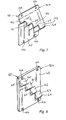
- Figures 5 and 6 depict further discharge deflector embodiments 52B and 52C that may be formed in somewhat similar manners from a unitary plate and which have a plurality of distinguishable upper ramp portions, such as the upper ramp portions 120-123 and 130-133.
- the formed discharge deflectors have a generally rectangular footprint.
- the discharge deflector may be formed from a somewhat fan-shaped or other shaped plate, rather than a rectangular plate, so that the formed construction will have a rectangular footprint.
- Figure 7 illustrates another discharge deflector 52F that could be similarly formed from different fan-shaped or other shaped plates, discharge deflector 52F including a plurality of upper ramp portions 150-153.
- Figure 8 depicts a still further discharge deflector embodiment 52H having a body 60 formed from a material plate and having a plurality of upper ramp portions 160-163 formed on the body, each of which ramp portions is braced by the thickness and bulk of the body and its material, and the material, thickness, and size of the upper ramp portions, especially relative to the entirety of such body.
- such body could be positioned on side wall 38 approximately three inches (76 mm) below the height of the axis of the rotor, and need extend towards the rear of the combine only a short distance since only a small length of deflector, on the order of one to three inches (25-76 mm), can serve to divert an adequate portion of the crop residue flow.
- the four upper ramp portions are angled similarly, although they could be angled differently if so desired.
- Such embodiment like the discharge deflector embodiments of Figures 5, 6 and 7, permits the concentrated flow of crop residue along side wall 38 to be separated into a plurality, in this case four, separate flow streams that are deflected transversely across the discharge passage in order to effect a more uniform introduction of crop residue to chopper 46.
- the upper and lower ramp portions have had faces that are generally straight and flat, it should be recognized that, in the practice of the present invention, the faces of such ramp portions need not necessarily be straight and flat, and that concave or convex or faceted faces could also be employed so long as the upper ramp portions are braced and remain essentially fixed and inflexible in normal use. Likewise, it should be understood that the backsides of such ramps need be of no particular form and could even extend back to and rest against the side wall so as to provide bracing for the upper ramp portions.
- flow D from threshing system 22 is centred about a centreline 72 which is offset from centreline 40 of threshing system 22.
- the crop residue flow F that is propelled rearwardly by chopper 46 is similarly offset in the same direction and centred about centreline 72.
- Flow F flows into crop residue spreader 26 in the offset manner, and spreader 26, in turn, propels the crop residue from the rear end of combine 20 in a similarly offset manner, as illustrated by large arrow G.
- the crop residue is spread unevenly over a swath of the field.
- a different embodiment of a crop residue spreader 26 is illustrated, including a pair of impellers rotatable about horizontal axes for discharging crop residue in opposite sideward directions, as illustrated by arrows H.
- the centred flow of crop residue F1 from chopper 46 and into spreader 26 results in more even inflow into spreader 26, such that outflows H will be more even, resulting in more uniform spreading characteristics.
Landscapes
- Life Sciences & Earth Sciences (AREA)
- Environmental Sciences (AREA)
- Threshing Machine Elements (AREA)
- Superconductive Dynamoelectric Machines (AREA)
- Paper (AREA)
- Braking Arrangements (AREA)
Applications Claiming Priority (2)
| Application Number | Priority Date | Filing Date | Title |
|---|---|---|---|
| US80837006P | 2006-05-25 | 2006-05-25 | |
| US11/804,118 US20080058042A1 (en) | 2006-05-25 | 2007-05-17 | Rigid rotor discharge deflector |
Publications (2)
| Publication Number | Publication Date |
|---|---|
| EP1859671A1 true EP1859671A1 (de) | 2007-11-28 |
| EP1859671B1 EP1859671B1 (de) | 2010-03-03 |
Family
ID=38421151
Family Applications (1)
| Application Number | Title | Priority Date | Filing Date |
|---|---|---|---|
| EP07108960A Active EP1859671B1 (de) | 2006-05-25 | 2007-05-25 | Starrer Rotorenentladungsdeflektor |
Country Status (4)
| Country | Link |
|---|---|
| US (3) | US20080058042A1 (de) |
| EP (1) | EP1859671B1 (de) |
| AT (1) | ATE459242T1 (de) |
| DE (1) | DE602007005045D1 (de) |
Cited By (3)
| Publication number | Priority date | Publication date | Assignee | Title |
|---|---|---|---|---|
| EP2364587A1 (de) * | 2010-03-10 | 2011-09-14 | CLAAS Selbstfahrende Erntemaschinen GmbH | Axialabscheider für einen Mähdrescher |
| EP1964465A3 (de) * | 2007-02-28 | 2012-02-29 | CNH Belgium N.V. | Einstellbarer Deflektor mit Achsenrotorenentladung |
| EP3714678A1 (de) * | 2019-03-27 | 2020-09-30 | CLAAS Selbstfahrende Erntemaschinen GmbH | Axialabscheider für einen mähdrescher |
Families Citing this family (7)
| Publication number | Priority date | Publication date | Assignee | Title |
|---|---|---|---|---|
| DE102010037416A1 (de) * | 2010-09-09 | 2012-03-15 | Claas Selbstfahrende Erntemaschinen Gmbh | Abscheideaggregat für einen Mähdrescher |
| EP2798943B1 (de) | 2013-05-01 | 2017-04-05 | CNH Industrial Belgium nv | Gegenschneidwerkschmutzableiter |
| CN106561172B (zh) * | 2016-10-25 | 2019-01-08 | 江苏大学 | 一种纵轴流联合收获机排草粉碎自适应抛撒装置及其控制方法 |
| US10426093B2 (en) | 2017-02-17 | 2019-10-01 | Cnh Industrial America Llc | Conical rotor discharge housing with adjustable vanes |
| US11832557B2 (en) * | 2018-04-11 | 2023-12-05 | Cnh Industrial America Llc | Rotational rotor discharge deflector |
| US11997946B2 (en) | 2019-04-25 | 2024-06-04 | Deere & Company | Access door with integral crop deflector for a combine harvester and method of manufacturing the same |
| US20240138317A1 (en) * | 2022-10-27 | 2024-05-02 | Deere & Company | Dual Rotor Deflector System and Method |
Citations (4)
| Publication number | Priority date | Publication date | Assignee | Title |
|---|---|---|---|---|
| US4177820A (en) * | 1978-04-07 | 1979-12-11 | Sperry Rand Corporation | Combine with offset rotor |
| US6241605B1 (en) | 1999-02-24 | 2001-06-05 | Deere & Company | Discharge geometry for axially arranged rotary separator |
| US6352474B1 (en) * | 2000-06-15 | 2002-03-05 | Deere & Company | Metering edge for axially arranged rotary separator |
| EP1754409A1 (de) * | 2005-08-15 | 2007-02-21 | CNH Belgium N.V. | Verstellbare Leitvorrichtung für Erntereste von einem Axialmähdreschersystem zu einer Resteverteilvorrichtung |
Family Cites Families (27)
| Publication number | Priority date | Publication date | Assignee | Title |
|---|---|---|---|---|
| US1509833A (en) * | 1924-01-19 | 1924-09-30 | King & Hamilton Company | Corn sheller |
| US1729199A (en) * | 1928-07-10 | 1929-09-24 | Franz J Wood | Spreader attachment for thrashing machines |
| US2246352A (en) * | 1938-04-05 | 1941-06-17 | Us Sugar Corp | Cleaning drum for cane harvesting apparatus |
| US2174836A (en) * | 1938-07-11 | 1939-10-03 | John M Range | Screen |
| US2383911A (en) * | 1941-11-06 | 1945-08-28 | Walter R Dray | Thresher machine |
| US3199441A (en) * | 1961-03-09 | 1965-08-10 | Haug Anton Joseph | Apparatus for draining fibrous material |
| US3626472A (en) * | 1969-01-09 | 1971-12-07 | Sperry Rand Corp | Means for feeding crop material to an axial flow threshing and separating combine |
| US3863643A (en) * | 1973-06-29 | 1975-02-04 | Int Harvester Co | Discharge chute and expansion chamber for an axial flow-type combine |
| US4003384A (en) * | 1976-03-29 | 1977-01-18 | Sperry Rand Corporation | Grain distribution means for rotary combine |
| US4175568A (en) * | 1978-07-14 | 1979-11-27 | Sperry Rand Corporation | Material flow retarders |
| CA1107169A (en) * | 1978-10-31 | 1981-08-18 | White Motor Corporation Of Canada Limited | Apparatus for discharging threshed materials directly from the rotor of an axial flow combine |
| US4249543A (en) * | 1979-11-02 | 1981-02-10 | Sperry Corporation | Rotor access module |
| US4306572A (en) * | 1980-07-24 | 1981-12-22 | Sperry Corporation | Axial flow stripper plate |
| US4677991A (en) * | 1986-01-31 | 1987-07-07 | Harris James R | Grain deflector for combines |
| US4706690A (en) * | 1986-12-04 | 1987-11-17 | Deutz-Allis Corporation | Crop director for a rotary combine |
| US4875890A (en) * | 1988-02-29 | 1989-10-24 | Ford New Holland, Inc. | Feed plate assembly for axial flow combine |
| US5145461A (en) * | 1991-03-21 | 1992-09-08 | Case Corporation | Door assembly for an axial-flow combine |
| US5145431A (en) * | 1991-04-10 | 1992-09-08 | Dowdeswell M Richard | Aquatic viewing apparatus |
| US5342239A (en) * | 1991-05-10 | 1994-08-30 | Deere & Company | Operation parameters for an axial separator |
| US5344367A (en) * | 1993-03-31 | 1994-09-06 | Deere & Company | Infeed plate for an axial agricultural combine |
| GB2356546A (en) * | 1999-11-26 | 2001-05-30 | Ford New Holland Nv | Threshing and separating unit for axial flow combines |
| DE10019640A1 (de) * | 2000-04-19 | 2002-04-18 | Claas Selbstfahr Erntemasch | Selbstfahrender Mähdrescher |
| DE10019667A1 (de) * | 2000-04-19 | 2002-01-03 | Claas Selbstfahr Erntemasch | Selbstfahrender Mähdrescher |
| DE10062429A1 (de) * | 2000-12-14 | 2002-07-11 | Claas Selbstfahr Erntemasch | Selbstfahrende Erntemaschine |
| US6602131B2 (en) * | 2001-12-12 | 2003-08-05 | Case Corporation | Multi-tier crop residue flow guide for an agricultural combine |
| US6755735B2 (en) * | 2002-07-19 | 2004-06-29 | Case Corporation | Unitary blow molded cover panel for a threshing region of an agricultural combine |
| US6979261B1 (en) * | 2004-10-15 | 2005-12-27 | Deere & Company | Dust reducing airflow diverter for combine |
-
2007
- 2007-05-17 US US11/804,118 patent/US20080058042A1/en not_active Abandoned
- 2007-05-25 AT AT07108960T patent/ATE459242T1/de not_active IP Right Cessation
- 2007-05-25 DE DE602007005045T patent/DE602007005045D1/de active Active
- 2007-05-25 EP EP07108960A patent/EP1859671B1/de active Active
-
2009
- 2009-04-03 US US12/384,385 patent/US20090197657A1/en not_active Abandoned
- 2009-04-03 US US12/384,383 patent/US7731576B2/en not_active Expired - Fee Related
Patent Citations (4)
| Publication number | Priority date | Publication date | Assignee | Title |
|---|---|---|---|---|
| US4177820A (en) * | 1978-04-07 | 1979-12-11 | Sperry Rand Corporation | Combine with offset rotor |
| US6241605B1 (en) | 1999-02-24 | 2001-06-05 | Deere & Company | Discharge geometry for axially arranged rotary separator |
| US6352474B1 (en) * | 2000-06-15 | 2002-03-05 | Deere & Company | Metering edge for axially arranged rotary separator |
| EP1754409A1 (de) * | 2005-08-15 | 2007-02-21 | CNH Belgium N.V. | Verstellbare Leitvorrichtung für Erntereste von einem Axialmähdreschersystem zu einer Resteverteilvorrichtung |
Cited By (3)
| Publication number | Priority date | Publication date | Assignee | Title |
|---|---|---|---|---|
| EP1964465A3 (de) * | 2007-02-28 | 2012-02-29 | CNH Belgium N.V. | Einstellbarer Deflektor mit Achsenrotorenentladung |
| EP2364587A1 (de) * | 2010-03-10 | 2011-09-14 | CLAAS Selbstfahrende Erntemaschinen GmbH | Axialabscheider für einen Mähdrescher |
| EP3714678A1 (de) * | 2019-03-27 | 2020-09-30 | CLAAS Selbstfahrende Erntemaschinen GmbH | Axialabscheider für einen mähdrescher |
Also Published As
| Publication number | Publication date |
|---|---|
| US20090197657A1 (en) | 2009-08-06 |
| EP1859671B1 (de) | 2010-03-03 |
| US7731576B2 (en) | 2010-06-08 |
| US20080058042A1 (en) | 2008-03-06 |
| ATE459242T1 (de) | 2010-03-15 |
| US20090197656A1 (en) | 2009-08-06 |
| DE602007005045D1 (de) | 2010-04-15 |
Similar Documents
| Publication | Publication Date | Title |
|---|---|---|
| EP1859671B1 (de) | Starrer Rotorenentladungsdeflektor | |
| EP1964465B1 (de) | Einstellbarer Entladungsdeflektor für Axialrotoren | |
| EP1754409B1 (de) | Verstellbare Leitvorrichtung für Erntereste von einem Axialmähdreschersystem zu einer Resteverteilvorrichtung | |
| EP2138024B1 (de) | Angetriebener Streuer für einen Mähdrescher | |
| US4209024A (en) | Axial flow combine with improved inlet transition area | |
| EP2286655B1 (de) | Erntegutrestehäcksel- und -verteilanordnung für einen Mähdrescher | |
| US10575471B2 (en) | Agricultural combine with reversing chopper rotor | |
| US8118651B2 (en) | Crop residue chopping and distributing arrangement for a combine | |
| US20030109293A1 (en) | Multi-tier crop residue flow guide for an agricultural combine | |
| EP2000019A1 (de) | Gegenmesservorrichtung für eine Häckselvorrichtung | |
| US6893340B1 (en) | Rotary accelerating apparatus for a vertical straw and chaff spreader of an agricultural combine | |
| EP3266297B1 (de) | Erntegutrestestreuer | |
| EP2298063B1 (de) | Dreschsystem | |
| EP3662737B1 (de) | Selbstfahrender mähdrescher | |
| EP1442651B1 (de) | Ernterestleiteinrichtung mit Durchflussfähigkeit für einen rotierbaren Erntereststreuer eines Mähdreschers | |
| EP3582605B1 (de) | Konisches rotor-entladungsgehäuse mit verstellbaren schaufeln | |
| US8147303B2 (en) | Harvested crop chopper remains and distribution arrangement for a combine | |
| US7028457B2 (en) | Threshing plate for a tailings conveyor of an agricultural combine | |
| US6991537B2 (en) | Deflector for a discharge outlet of a tailings conveyor of an agricultural combine | |
| US6976914B2 (en) | Impeller with swept back blades for a tailings conveyor of an agricultural combine | |
| JP2554872Y2 (ja) | 脱穀装置における扱胴 |
Legal Events
| Date | Code | Title | Description |
|---|---|---|---|
| PUAI | Public reference made under article 153(3) epc to a published international application that has entered the european phase |
Free format text: ORIGINAL CODE: 0009012 |
|
| AK | Designated contracting states |
Kind code of ref document: A1 Designated state(s): AT BE BG CH CY CZ DE DK EE ES FI FR GB GR HU IE IS IT LI LT LU LV MC MT NL PL PT RO SE SI SK TR |
|
| AX | Request for extension of the european patent |
Extension state: AL BA HR MK YU |
|
| RIN1 | Information on inventor provided before grant (corrected) |
Inventor name: WAGNER, BRADLEY J. Inventor name: YDE, LUC A. Inventor name: RICKETTS, JONATHAN E. Inventor name: ISAAC, NATHAN A. |
|
| 17P | Request for examination filed |
Effective date: 20080528 |
|
| 17Q | First examination report despatched |
Effective date: 20080702 |
|
| AKX | Designation fees paid |
Designated state(s): AT BE BG CH CY CZ DE DK EE ES FI FR GB GR HU IE IS IT LI LT LU LV MC MT NL PL PT RO SE SI SK TR |
|
| GRAP | Despatch of communication of intention to grant a patent |
Free format text: ORIGINAL CODE: EPIDOSNIGR1 |
|
| GRAS | Grant fee paid |
Free format text: ORIGINAL CODE: EPIDOSNIGR3 |
|
| GRAA | (expected) grant |
Free format text: ORIGINAL CODE: 0009210 |
|
| AK | Designated contracting states |
Kind code of ref document: B1 Designated state(s): AT BE BG CH CY CZ DE DK EE ES FI FR GB GR HU IE IS IT LI LT LU LV MC MT NL PL PT RO SE SI SK TR |
|
| REG | Reference to a national code |
Ref country code: GB Ref legal event code: FG4D |
|
| REG | Reference to a national code |
Ref country code: CH Ref legal event code: EP |
|
| REG | Reference to a national code |
Ref country code: IE Ref legal event code: FG4D |
|
| REF | Corresponds to: |
Ref document number: 602007005045 Country of ref document: DE Date of ref document: 20100415 Kind code of ref document: P |
|
| REG | Reference to a national code |
Ref country code: NL Ref legal event code: VDEP Effective date: 20100303 |
|
| PG25 | Lapsed in a contracting state [announced via postgrant information from national office to epo] |
Ref country code: LT Free format text: LAPSE BECAUSE OF FAILURE TO SUBMIT A TRANSLATION OF THE DESCRIPTION OR TO PAY THE FEE WITHIN THE PRESCRIBED TIME-LIMIT Effective date: 20100303 |
|
| LTIE | Lt: invalidation of european patent or patent extension |
Effective date: 20100303 |
|
| PG25 | Lapsed in a contracting state [announced via postgrant information from national office to epo] |
Ref country code: SI Free format text: LAPSE BECAUSE OF FAILURE TO SUBMIT A TRANSLATION OF THE DESCRIPTION OR TO PAY THE FEE WITHIN THE PRESCRIBED TIME-LIMIT Effective date: 20100303 Ref country code: PL Free format text: LAPSE BECAUSE OF FAILURE TO SUBMIT A TRANSLATION OF THE DESCRIPTION OR TO PAY THE FEE WITHIN THE PRESCRIBED TIME-LIMIT Effective date: 20100303 Ref country code: LV Free format text: LAPSE BECAUSE OF FAILURE TO SUBMIT A TRANSLATION OF THE DESCRIPTION OR TO PAY THE FEE WITHIN THE PRESCRIBED TIME-LIMIT Effective date: 20100303 Ref country code: AT Free format text: LAPSE BECAUSE OF FAILURE TO SUBMIT A TRANSLATION OF THE DESCRIPTION OR TO PAY THE FEE WITHIN THE PRESCRIBED TIME-LIMIT Effective date: 20100303 Ref country code: FI Free format text: LAPSE BECAUSE OF FAILURE TO SUBMIT A TRANSLATION OF THE DESCRIPTION OR TO PAY THE FEE WITHIN THE PRESCRIBED TIME-LIMIT Effective date: 20100303 |
|
| PG25 | Lapsed in a contracting state [announced via postgrant information from national office to epo] |
Ref country code: EE Free format text: LAPSE BECAUSE OF FAILURE TO SUBMIT A TRANSLATION OF THE DESCRIPTION OR TO PAY THE FEE WITHIN THE PRESCRIBED TIME-LIMIT Effective date: 20100303 Ref country code: CY Free format text: LAPSE BECAUSE OF FAILURE TO SUBMIT A TRANSLATION OF THE DESCRIPTION OR TO PAY THE FEE WITHIN THE PRESCRIBED TIME-LIMIT Effective date: 20100303 Ref country code: BE Free format text: LAPSE BECAUSE OF FAILURE TO SUBMIT A TRANSLATION OF THE DESCRIPTION OR TO PAY THE FEE WITHIN THE PRESCRIBED TIME-LIMIT Effective date: 20100303 Ref country code: SE Free format text: LAPSE BECAUSE OF FAILURE TO SUBMIT A TRANSLATION OF THE DESCRIPTION OR TO PAY THE FEE WITHIN THE PRESCRIBED TIME-LIMIT Effective date: 20100303 Ref country code: ES Free format text: LAPSE BECAUSE OF FAILURE TO SUBMIT A TRANSLATION OF THE DESCRIPTION OR TO PAY THE FEE WITHIN THE PRESCRIBED TIME-LIMIT Effective date: 20100614 Ref country code: RO Free format text: LAPSE BECAUSE OF FAILURE TO SUBMIT A TRANSLATION OF THE DESCRIPTION OR TO PAY THE FEE WITHIN THE PRESCRIBED TIME-LIMIT Effective date: 20100303 Ref country code: GR Free format text: LAPSE BECAUSE OF FAILURE TO SUBMIT A TRANSLATION OF THE DESCRIPTION OR TO PAY THE FEE WITHIN THE PRESCRIBED TIME-LIMIT Effective date: 20100604 Ref country code: NL Free format text: LAPSE BECAUSE OF FAILURE TO SUBMIT A TRANSLATION OF THE DESCRIPTION OR TO PAY THE FEE WITHIN THE PRESCRIBED TIME-LIMIT Effective date: 20100303 |
|
| PG25 | Lapsed in a contracting state [announced via postgrant information from national office to epo] |
Ref country code: IS Free format text: LAPSE BECAUSE OF FAILURE TO SUBMIT A TRANSLATION OF THE DESCRIPTION OR TO PAY THE FEE WITHIN THE PRESCRIBED TIME-LIMIT Effective date: 20100703 Ref country code: BG Free format text: LAPSE BECAUSE OF FAILURE TO SUBMIT A TRANSLATION OF THE DESCRIPTION OR TO PAY THE FEE WITHIN THE PRESCRIBED TIME-LIMIT Effective date: 20100603 Ref country code: CZ Free format text: LAPSE BECAUSE OF FAILURE TO SUBMIT A TRANSLATION OF THE DESCRIPTION OR TO PAY THE FEE WITHIN THE PRESCRIBED TIME-LIMIT Effective date: 20100303 Ref country code: SK Free format text: LAPSE BECAUSE OF FAILURE TO SUBMIT A TRANSLATION OF THE DESCRIPTION OR TO PAY THE FEE WITHIN THE PRESCRIBED TIME-LIMIT Effective date: 20100303 |
|
| PG25 | Lapsed in a contracting state [announced via postgrant information from national office to epo] |
Ref country code: MC Free format text: LAPSE BECAUSE OF NON-PAYMENT OF DUE FEES Effective date: 20100531 |
|
| PLBE | No opposition filed within time limit |
Free format text: ORIGINAL CODE: 0009261 |
|
| STAA | Information on the status of an ep patent application or granted ep patent |
Free format text: STATUS: NO OPPOSITION FILED WITHIN TIME LIMIT |
|
| PG25 | Lapsed in a contracting state [announced via postgrant information from national office to epo] |
Ref country code: PT Free format text: LAPSE BECAUSE OF FAILURE TO SUBMIT A TRANSLATION OF THE DESCRIPTION OR TO PAY THE FEE WITHIN THE PRESCRIBED TIME-LIMIT Effective date: 20100705 Ref country code: DK Free format text: LAPSE BECAUSE OF FAILURE TO SUBMIT A TRANSLATION OF THE DESCRIPTION OR TO PAY THE FEE WITHIN THE PRESCRIBED TIME-LIMIT Effective date: 20100303 |
|
| 26N | No opposition filed |
Effective date: 20101206 |
|
| PG25 | Lapsed in a contracting state [announced via postgrant information from national office to epo] |
Ref country code: IT Free format text: LAPSE BECAUSE OF NON-PAYMENT OF DUE FEES Effective date: 20100525 |
|
| PG25 | Lapsed in a contracting state [announced via postgrant information from national office to epo] |
Ref country code: IE Free format text: LAPSE BECAUSE OF NON-PAYMENT OF DUE FEES Effective date: 20100525 Ref country code: MT Free format text: LAPSE BECAUSE OF FAILURE TO SUBMIT A TRANSLATION OF THE DESCRIPTION OR TO PAY THE FEE WITHIN THE PRESCRIBED TIME-LIMIT Effective date: 20100303 |
|
| REG | Reference to a national code |
Ref country code: CH Ref legal event code: PL |
|
| PG25 | Lapsed in a contracting state [announced via postgrant information from national office to epo] |
Ref country code: CH Free format text: LAPSE BECAUSE OF NON-PAYMENT OF DUE FEES Effective date: 20110531 Ref country code: LI Free format text: LAPSE BECAUSE OF NON-PAYMENT OF DUE FEES Effective date: 20110531 |
|
| PG25 | Lapsed in a contracting state [announced via postgrant information from national office to epo] |
Ref country code: HU Free format text: LAPSE BECAUSE OF FAILURE TO SUBMIT A TRANSLATION OF THE DESCRIPTION OR TO PAY THE FEE WITHIN THE PRESCRIBED TIME-LIMIT Effective date: 20100904 Ref country code: LU Free format text: LAPSE BECAUSE OF NON-PAYMENT OF DUE FEES Effective date: 20100525 |
|
| PG25 | Lapsed in a contracting state [announced via postgrant information from national office to epo] |
Ref country code: TR Free format text: LAPSE BECAUSE OF FAILURE TO SUBMIT A TRANSLATION OF THE DESCRIPTION OR TO PAY THE FEE WITHIN THE PRESCRIBED TIME-LIMIT Effective date: 20100303 |
|
| REG | Reference to a national code |
Ref country code: DE Ref legal event code: R082 Ref document number: 602007005045 Country of ref document: DE Representative=s name: PATENTANWAELTE WALLACH, KOCH & PARTNER, DE |
|
| REG | Reference to a national code |
Ref country code: DE Ref legal event code: R081 Ref document number: 602007005045 Country of ref document: DE Owner name: CNH INDUSTRIAL BELGIUM NV, BE Free format text: FORMER OWNER: CNH BELGIUM NV, ZEDELGEM, BE Effective date: 20140428 Ref country code: DE Ref legal event code: R082 Ref document number: 602007005045 Country of ref document: DE Representative=s name: PATENTANWAELTE WALLACH, KOCH & PARTNER, DE Effective date: 20140428 Ref country code: DE Ref legal event code: R082 Ref document number: 602007005045 Country of ref document: DE Representative=s name: PATENTANWAELTE WALLACH, KOCH, DR. HAIBACH, FEL, DE Effective date: 20140428 |
|
| REG | Reference to a national code |
Ref country code: FR Ref legal event code: CD Owner name: CNH INDUSTRIAL BELGIUM NV Effective date: 20140725 |
|
| REG | Reference to a national code |
Ref country code: FR Ref legal event code: PLFP Year of fee payment: 10 |
|
| REG | Reference to a national code |
Ref country code: FR Ref legal event code: PLFP Year of fee payment: 11 |
|
| REG | Reference to a national code |
Ref country code: FR Ref legal event code: PLFP Year of fee payment: 12 |
|
| REG | Reference to a national code |
Ref country code: DE Ref legal event code: R082 Ref document number: 602007005045 Country of ref document: DE Representative=s name: MEISSNER BOLTE PATENTANWAELTE RECHTSANWAELTE P, DE |
|
| PGFP | Annual fee paid to national office [announced via postgrant information from national office to epo] |
Ref country code: GB Payment date: 20200528 Year of fee payment: 14 |
|
| REG | Reference to a national code |
Ref country code: DE Ref legal event code: R084 Ref document number: 602007005045 Country of ref document: DE |
|
| GBPC | Gb: european patent ceased through non-payment of renewal fee |
Effective date: 20210525 |
|
| PG25 | Lapsed in a contracting state [announced via postgrant information from national office to epo] |
Ref country code: GB Free format text: LAPSE BECAUSE OF NON-PAYMENT OF DUE FEES Effective date: 20210525 |
|
| PGFP | Annual fee paid to national office [announced via postgrant information from national office to epo] |
Ref country code: FR Payment date: 20240522 Year of fee payment: 18 |
|
| PGFP | Annual fee paid to national office [announced via postgrant information from national office to epo] |
Ref country code: DE Payment date: 20250528 Year of fee payment: 19 |
|
| PGFP | Annual fee paid to national office [announced via postgrant information from national office to epo] |
Ref country code: IT Payment date: 20250522 Year of fee payment: 19 |
|
| PG25 | Lapsed in a contracting state [announced via postgrant information from national office to epo] |
Ref country code: FR Free format text: LAPSE BECAUSE OF NON-PAYMENT OF DUE FEES Effective date: 20250531 |