EP1859711A2 - Verbesserte Heizgefäße für Flüssigkeiten - Google Patents
Verbesserte Heizgefäße für Flüssigkeiten Download PDFInfo
- Publication number
- EP1859711A2 EP1859711A2 EP07252137A EP07252137A EP1859711A2 EP 1859711 A2 EP1859711 A2 EP 1859711A2 EP 07252137 A EP07252137 A EP 07252137A EP 07252137 A EP07252137 A EP 07252137A EP 1859711 A2 EP1859711 A2 EP 1859711A2
- Authority
- EP
- European Patent Office
- Prior art keywords
- heater
- vessel
- disrupter member
- liquid heating
- heating element
- Prior art date
- Legal status (The legal status is an assumption and is not a legal conclusion. Google has not performed a legal analysis and makes no representation as to the accuracy of the status listed.)
- Granted
Links
Images



Classifications
-
- A—HUMAN NECESSITIES
- A47—FURNITURE; DOMESTIC ARTICLES OR APPLIANCES; COFFEE MILLS; SPICE MILLS; SUCTION CLEANERS IN GENERAL
- A47J—KITCHEN EQUIPMENT; COFFEE MILLS; SPICE MILLS; APPARATUS FOR MAKING BEVERAGES
- A47J27/00—Cooking-vessels
- A47J27/21—Water-boiling vessels, e.g. kettles
- A47J27/21166—Constructional details or accessories
-
- A—HUMAN NECESSITIES
- A47—FURNITURE; DOMESTIC ARTICLES OR APPLIANCES; COFFEE MILLS; SPICE MILLS; SUCTION CLEANERS IN GENERAL
- A47J—KITCHEN EQUIPMENT; COFFEE MILLS; SPICE MILLS; APPARATUS FOR MAKING BEVERAGES
- A47J36/00—Parts, details or accessories of cooking-vessels
- A47J36/16—Inserts
-
- A—HUMAN NECESSITIES
- A47—FURNITURE; DOMESTIC ARTICLES OR APPLIANCES; COFFEE MILLS; SPICE MILLS; SUCTION CLEANERS IN GENERAL
- A47J—KITCHEN EQUIPMENT; COFFEE MILLS; SPICE MILLS; APPARATUS FOR MAKING BEVERAGES
- A47J27/00—Cooking-vessels
- A47J27/21—Water-boiling vessels, e.g. kettles
- A47J27/21008—Water-boiling vessels, e.g. kettles electrically heated
- A47J27/21041—Water-boiling vessels, e.g. kettles electrically heated with heating elements arranged outside the water vessel
-
- A—HUMAN NECESSITIES
- A47—FURNITURE; DOMESTIC ARTICLES OR APPLIANCES; COFFEE MILLS; SPICE MILLS; SUCTION CLEANERS IN GENERAL
- A47J—KITCHEN EQUIPMENT; COFFEE MILLS; SPICE MILLS; APPARATUS FOR MAKING BEVERAGES
- A47J27/00—Cooking-vessels
- A47J27/56—Preventing boiling over, e.g. of milk
- A47J27/60—Funnel-like inserts; Grooved plates to be placed on the bottom of cooking utensils
Definitions
- This invention relates to the reduction of noise in liquid heating vessels, particularly water boiling vessels.
- the pressure inside a spherical bubble is inversely proportional to its radius. Thus very small bubbles have very high internal pressures. Bubble formation is initially enabled by surface imperfections such as crevices or particles of precipitated scale, and so the bubbles are not spherical. However the bubbles are approximately spherical as they grow. The growth reaches a critical point where the bubbles start to collapse as they condense on meeting a cooler layer of water and so their pressures rise rapidly (possibly reaching of the order of tens of thousands of atmospheres). As this happens at between 400 - 900 Hz, a loud whistle at those frequencies is generated. It has been found that the whistle is most prevalent at temperatures between 60 and 90°C.
- the present invention seeks to alleviate the aforementioned problem and when viewed from a first aspect the invention provides a liquid heating vessel comprising a heater forming at least part of the base of the vessel, the heater comprising a heater plate and an electric heating element attached to or formed on the underside of the heater plate, the vessel further comprising a disrupter member having a surface disposed above and extending over at least part of the upper surface of the heater plate opposite where the heating element is provided, said disrupter member being arranged in use to partially isolate a layer of liquid directly above the heating element.
- the disrupter member could be attached to or integral with a wall of the vessel. However this might be difficult to produce and has the disadvantage that it places the burden of properly locating it on the appliance manufacturers. In preferred embodiments therefore the disrupter member is attached to the heater. This is extremely convenient in that it does not require any special features to be formed on the vessel wall and so allows the heater assembly to be fitted into virtually any vessel in place of a conventional heater and does not limit design freedom.
- the invention When viewed from a second aspect therefore the invention provides a heater assembly for a liquid heating vessel comprising:
- the disrupter member may extend over just part of the heater surface above the element, but preferably the whole of the element is directly beneath the member.
- the surface of the disrupter member would be arcuate.
- the disrupter member surface is annular.
- the invention is not limited to horse-shoe shaped sheathed elements. It could apply equally to other sheathed elements or to thick-film heating elements in which a conductive track is applied to the underside of the heater plate.
- the disrupter member surface could be continuous or discontinuous.
- the discontinuity may be manifested as a series of separate, discrete surface regions over the element or, more preferably, an array of apertures in the surface.
- An apertured surface is preferred as it has been found to reduce the tendency to for the vessel to 'knock' as bubbles coalesce and escape from beneath the disrupter member in a 'glugging' action.
- Such apertures could take any convenient size and shape - e.g. circular holes, radial slots, arcuate slots, diagonal slots etc.
- the apertures need not be the same size or shape and could be distributed evenly or unevenly; regularly or randomly.
- the disrupter member could be made of any suitable material, e.g. plastics. This would have the advantage of low cost. In some preferred embodiments however it is made from stainless steel as this had been found to give the best noise reduction.
- the disrupter member disclosed herein is potentially of benefit in reducing noise in any heater which might be subject to scale.
- the whistling phenomenon referred to in the introduction hereinabove is one which arises when a noise-reduction coating has been applied to the heater surface, the invention is especially applicable to such heaters.
- the heater surface comprises a noise-reduction coating.
- the noise-reduction coating is hydrophobic.
- the coating could comprise adjacent regions with different surface tension properties.
- the coating comprises a silicon-based material - e.g. Akzo-Nobel X10106.
- the coating could be continuous or discontinuous at the macro level, e.g. being striped; or at the micro level, e.g. by being cracked.
- Figs. 1a and 1b show an underfloor heater with which the invention may be used.
- the heater comprises a thin (e.g. 0.5 to 1 mm) stainless steel heater plate 2 which is formed with a dished central portion and an upwardly open peripheral channel 4 in accordance with the applicant's Sure Seal sealing system which is described in greater detail in WO 96/18331 .
- the heater plate 2 is completely conventional except in two respects. The first of these is that the central portion 6 of the plate is provided with a noise reduction coating in the form of a layer of Akzo-Nobel X10106 silicone-based coating which has been fired so as to produce a surface micro-cracking effect.
- the second non-conventional feature is a hole 8 in the centre of the plate, the purpose of which will become clear below.
- an aluminium heat diffuser plate 10 which is brazed onto the underside of the central portion 6.
- a horseshoe-shaped sheathed heating element 12 is brazed onto the underside of the diffuser plate 10 as is conventional in the art.
- the diffuser plate 10 has a large hole 14 at its centre in which the hole 8 through the plate 2 is located.
- Three threaded bosses 16 for mounting a control unit are also fixed to the diffuser plate 10.
- FIG. 2 shows a disrupter member 18 according to an embodiment of the invention.
- the disrupter member 18 is moulded from a heat-resistant plastics material such as acetyl or talc filled polypropylene. In another alternative it could be of stainless steel. It is formed with a main annular surface 20 which is supported by three spokes 22 meeting at a central hub 24. A spigot 26 extends down from the hub 24 in order to mount the disrupter member 18 to the heater plate 2 as is shown in Fig. 3.
- a heat-resistant plastics material such as acetyl or talc filled polypropylene. In another alternative it could be of stainless steel.
- It is formed with a main annular surface 20 which is supported by three spokes 22 meeting at a central hub 24.
- a spigot 26 extends down from the hub 24 in order to mount the disrupter member 18 to the heater plate 2 as is shown in Fig. 3.
- FIG 3 is a sectional view through the assembled heater and disrupter member. It may be seen from here that the downwardly projecting spigot 26 of the disrupter member is received in a silicone rubber plug 28 which is a tight sealing fit in the hole 8 in the centre of the heating plate 2. As will be seen, the silicone plug 28 has an upper annular rim 30 which abuts against an annular flange 32 around the top of the disrupter member's spigot 26. This arrangement serves to support the disrupter member 18 above the surface 6 of the heater plate. For example, it can be seen that the annular surface 20 of the disrupter member is spaced vertically from the heater plate surface 6 by of the order of 4-8 mm.
- the main annular surface 20 of the disrupter member is located vertically above the part of the heater surface 6 opposite where the heating element 12 is attached.
- the disrupter member annular surface 20 therefore extends over the part of the water contacting surface 6 of the heater which is most directly heated.
- the silicone plug 28 also provides thermal isolation from the heater surface to prevent the disrupter member 18 from being damaged by overheating. This is further assisted by the large circular hole 8 in the centre of the aluminium diffuser plate 10 (see Fig. 1b) which means that the only direct path from the heating element 12 to the plug 28 is via the thin stainless steel at the centre of the heater plate which is a poor thermal conductor. There is an additional benefit in that it gives a reduction in the material cost of the diffuser plate.
- the annular surface 20 of the disrupter member is angled slightly downwardly towards its periphery although this is not essential.
- the disrupter member is shown with a thin lip 33 extending downwardly from the radially inner edge of the annular surface 20, but this could be omitted.
- the heater plate 2 is a Sure Seal plate (i.e. it has an upwardly open peripheral channel) this may in use be fitted to a plastics vessel simply by clamping a downwardly depending portion of the vessel wall in the channel 4 exactly as is described in WO 96/18331 .
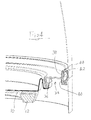
- the heater plate 2 is instead fitted into the vessel by means of an intermediate adapter ring 34 as shown in Figure 4. It should be noted that in Figure 4 the disrupter member has been omitted for clarity. However, what may be seen in Fig.
- the adapter ring 34 has an annular wall 36 extending downwardly from its radially inner edge which is received in the upwardly open channel 4 of the heater plate thereby allowing the heater plate 2 to be fitted to the adaptor ring 34 by the standard Sure Seal technique set out in WO 96/18331 .
- annular wall portions 38,40 extend upwardly and downwardly to interface with an annular seal 42 having a rolled-over cross-sectional profile and which seals the adaptor ring 34 against the inner face of the vessel wall 44.
- the assembly is held into the vessel against the taper of the vessel wall 44 by a suitable clip such as a circlip or a radially expanding spider clip.
- the heating element 12 is energised causing it to heat rapidly. It may, for example, be rated at between 2 and 3 kW.
- the predominant thermal path from the element 12 is directly up through the heat diffuser plate 10 and the stainless steel heater plate 2 into the water.
- the noise reduction coating on the central part 6 of the heater surface will prevent the bubbles generated by inevitable nucleate boiling at the heater surface from growing too large and so it will minimise the background heating noise.
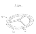
- Figs. 5, 6 and 7 show alternative embodiments of the disrupter member.
- the disrupter member 46,48,50 respectively has the same basic shape as the disrupter member 18 of the first embodiment but is provided with an array of apertures in the annular surface 52,54,56.
- the apertures comprise small circular holes 58 evenly distributed around the annular surface 52.
- the embodiment of Figure 6 is very similar except that the holes 58' are larger.
- the embodiment of Figure 7 has apertures in the form of arcuate slots 60 which are concentric with the annular surface 56.
- the presence of the apertures 58,58',60 enable steam to escape from under the corresponding annular surface 52,54,56 more readily in the first embodiment which can reduce the tendency for "glugging" to occur and the associated rocking of the kettle.
- the disrupter member need not be generally annular in shape, it may have any other convenient shape. Similarly, it may not extend around a complete revolution but might have a more limited angular extent. Similarly, the disrupter member need not be attached to the heater but could instead by attached to the wall of the vessel or some other structure such as the adapter ring shown in Figure 4 or similar component. Furthermore, although the invention has been described in conjunction with a noise reduction coating, this is not considered to be essential and the invention may provide benefit in heaters where a noise reduction coating is not provided.
Landscapes
- Engineering & Computer Science (AREA)
- Food Science & Technology (AREA)
- Cookers (AREA)
- Coating Apparatus (AREA)
Applications Claiming Priority (1)
| Application Number | Priority Date | Filing Date | Title |
|---|---|---|---|
| GBGB0610427.7A GB0610427D0 (en) | 2006-05-25 | 2006-05-25 | Improvements in liquid heating vessels |
Publications (3)
| Publication Number | Publication Date |
|---|---|
| EP1859711A2 true EP1859711A2 (de) | 2007-11-28 |
| EP1859711A3 EP1859711A3 (de) | 2008-10-22 |
| EP1859711B1 EP1859711B1 (de) | 2009-08-26 |
Family
ID=36687747
Family Applications (1)
| Application Number | Title | Priority Date | Filing Date |
|---|---|---|---|
| EP07252137A Not-in-force EP1859711B1 (de) | 2006-05-25 | 2007-05-24 | Verbesserte Heizgefäße für Flüssigkeiten |
Country Status (7)
| Country | Link |
|---|---|
| EP (1) | EP1859711B1 (de) |
| CN (1) | CN101078560A (de) |
| AT (1) | ATE440525T1 (de) |
| AU (1) | AU2007202358A1 (de) |
| DE (1) | DE602007002106D1 (de) |
| GB (1) | GB0610427D0 (de) |
| NZ (1) | NZ555375A (de) |
Cited By (3)
| Publication number | Priority date | Publication date | Assignee | Title |
|---|---|---|---|---|
| GB2445070A (en) * | 2006-12-14 | 2008-06-25 | Otter Controls Ltd | Noise reduction in electric water-heating vessels |
| AU2007331268B2 (en) * | 2006-12-14 | 2014-03-06 | Otter Controls Ltd | Electric water heater |
| AU2015224376B2 (en) * | 2015-09-07 | 2021-08-05 | Newell Australia Pty Ltd | Heating vessel with noise reduction |
Families Citing this family (3)
| Publication number | Priority date | Publication date | Assignee | Title |
|---|---|---|---|---|
| JP5320407B2 (ja) * | 2007-12-24 | 2013-10-23 | ストリックス リミテッド | 液体加熱装置 |
| CN109805748B (zh) * | 2017-11-21 | 2024-05-28 | 广东美的生活电器制造有限公司 | 内胆组件以及液体加热器 |
| CN117297320A (zh) * | 2023-09-28 | 2023-12-29 | 艾瑞森表面技术(苏州)股份有限公司 | 一种降噪液体加热容器及其加热底盘的制备方法 |
Family Cites Families (3)
| Publication number | Priority date | Publication date | Assignee | Title |
|---|---|---|---|---|
| NL1015204C2 (nl) * | 2000-05-15 | 2001-11-19 | Nedap Nv | Inrichting voor het nagenoeg geruisloos verwarmen en/of koken van water. |
| GB2386532B (en) * | 2001-11-29 | 2005-12-21 | Strix Ltd | Electric water heaters |
| WO2008071983A2 (en) * | 2006-12-14 | 2008-06-19 | Otter Controls Ltd | Electric water heater |
-
2006
- 2006-05-25 GB GBGB0610427.7A patent/GB0610427D0/en not_active Ceased
-
2007
- 2007-05-24 DE DE602007002106T patent/DE602007002106D1/de active Active
- 2007-05-24 AU AU2007202358A patent/AU2007202358A1/en not_active Abandoned
- 2007-05-24 AT AT07252137T patent/ATE440525T1/de not_active IP Right Cessation
- 2007-05-24 EP EP07252137A patent/EP1859711B1/de not_active Not-in-force
- 2007-05-24 NZ NZ555375A patent/NZ555375A/en not_active IP Right Cessation
- 2007-05-25 CN CNA2007101283008A patent/CN101078560A/zh active Pending
Cited By (4)
| Publication number | Priority date | Publication date | Assignee | Title |
|---|---|---|---|---|
| GB2445070A (en) * | 2006-12-14 | 2008-06-25 | Otter Controls Ltd | Noise reduction in electric water-heating vessels |
| GB2445070B (en) * | 2006-12-14 | 2011-12-28 | Otter Controls Ltd | Electric water heater |
| AU2007331268B2 (en) * | 2006-12-14 | 2014-03-06 | Otter Controls Ltd | Electric water heater |
| AU2015224376B2 (en) * | 2015-09-07 | 2021-08-05 | Newell Australia Pty Ltd | Heating vessel with noise reduction |
Also Published As
| Publication number | Publication date |
|---|---|
| DE602007002106D1 (de) | 2009-10-08 |
| AU2007202358A1 (en) | 2007-12-13 |
| NZ555375A (en) | 2009-02-28 |
| GB0610427D0 (en) | 2006-07-05 |
| CN101078560A (zh) | 2007-11-28 |
| EP1859711A3 (de) | 2008-10-22 |
| EP1859711B1 (de) | 2009-08-26 |
| ATE440525T1 (de) | 2009-09-15 |
Similar Documents
| Publication | Publication Date | Title |
|---|---|---|
| EP1859711B1 (de) | Verbesserte Heizgefäße für Flüssigkeiten | |
| CN113840559B (zh) | 水壶 | |
| EP2725948B1 (de) | Elektrisch beheiztes gefäss | |
| EP2064975B1 (de) | Heizgefäß für Flüssigkeiten | |
| CN205514171U (zh) | 发热盘及烹饪器具 | |
| JP6253684B2 (ja) | 炊飯器および容器 | |
| TWI623291B (zh) | Rice cooker | |
| CN109875386B (zh) | 米饭口感均衡的电饭煲 | |
| JP2009254505A (ja) | 電気炊飯器 | |
| CN210961469U (zh) | 一种低成本的电压力锅 | |
| CN222382990U (zh) | 烹饪器具 | |
| CN224140611U (zh) | 锅胆和烹饪器具 | |
| CN210673020U (zh) | 一种米饭烹饪器具均匀传热发热盘及米饭烹饪器具 | |
| CN108652439B (zh) | 电水壶 | |
| CN220124494U (zh) | 烹饪器具 | |
| AU2015224376B2 (en) | Heating vessel with noise reduction | |
| CN100394877C (zh) | 电加热的液体加热容器及其加热器 | |
| JP7360652B2 (ja) | Ih用調理容器 | |
| GB2407255A (en) | An electric cooking device with insulating inter-wall support structure | |
| CN210961477U (zh) | 一种电磁加热的电压力锅 | |
| GB2456318A (en) | A device to prevent cooking vessels from boiling over | |
| KR200357102Y1 (ko) | 압력밥솥 | |
| CN211269999U (zh) | 一种低成本的电压力锅 | |
| JP2010042100A (ja) | 吹きこぼれ防止具およびそれを利用した調理容器支持具 | |
| CN207012106U (zh) | 发热盘及烹饪器具 |
Legal Events
| Date | Code | Title | Description |
|---|---|---|---|
| PUAI | Public reference made under article 153(3) epc to a published international application that has entered the european phase |
Free format text: ORIGINAL CODE: 0009012 |
|
| AK | Designated contracting states |
Kind code of ref document: A2 Designated state(s): AT BE BG CH CY CZ DE DK EE ES FI FR GB GR HU IE IS IT LI LT LU LV MC MT NL PL PT RO SE SI SK TR |
|
| AX | Request for extension of the european patent |
Extension state: AL BA HR MK YU |
|
| PUAL | Search report despatched |
Free format text: ORIGINAL CODE: 0009013 |
|
| 17P | Request for examination filed |
Effective date: 20080825 |
|
| AK | Designated contracting states |
Kind code of ref document: A3 Designated state(s): AT BE BG CH CY CZ DE DK EE ES FI FR GB GR HU IE IS IT LI LT LU LV MC MT NL PL PT RO SE SI SK TR |
|
| AX | Request for extension of the european patent |
Extension state: AL BA HR MK RS |
|
| RIC1 | Information provided on ipc code assigned before grant |
Ipc: A47J 27/21 20060101AFI20071009BHEP Ipc: A47J 36/16 20060101ALI20080917BHEP Ipc: A47J 27/60 20060101ALN20080917BHEP |
|
| GRAP | Despatch of communication of intention to grant a patent |
Free format text: ORIGINAL CODE: EPIDOSNIGR1 |
|
| AKX | Designation fees paid |
Designated state(s): AT BE BG CH CY CZ DE DK EE ES FI FR GB GR HU IE IS IT LI LT LU LV MC MT NL PL PT RO SE SI SK TR |
|
| GRAS | Grant fee paid |
Free format text: ORIGINAL CODE: EPIDOSNIGR3 |
|
| GRAA | (expected) grant |
Free format text: ORIGINAL CODE: 0009210 |
|
| AK | Designated contracting states |
Kind code of ref document: B1 Designated state(s): AT BE BG CH CY CZ DE DK EE ES FI FR GB GR HU IE IS IT LI LT LU LV MC MT NL PL PT RO SE SI SK TR |
|
| REG | Reference to a national code |
Ref country code: GB Ref legal event code: FG4D |
|
| REG | Reference to a national code |
Ref country code: CH Ref legal event code: EP |
|
| REG | Reference to a national code |
Ref country code: IE Ref legal event code: FG4D |
|
| REF | Corresponds to: |
Ref document number: 602007002106 Country of ref document: DE Date of ref document: 20091008 Kind code of ref document: P |
|
| LTIE | Lt: invalidation of european patent or patent extension |
Effective date: 20090826 |
|
| PG25 | Lapsed in a contracting state [announced via postgrant information from national office to epo] |
Ref country code: SE Free format text: LAPSE BECAUSE OF FAILURE TO SUBMIT A TRANSLATION OF THE DESCRIPTION OR TO PAY THE FEE WITHIN THE PRESCRIBED TIME-LIMIT Effective date: 20090826 Ref country code: IS Free format text: LAPSE BECAUSE OF FAILURE TO SUBMIT A TRANSLATION OF THE DESCRIPTION OR TO PAY THE FEE WITHIN THE PRESCRIBED TIME-LIMIT Effective date: 20091226 Ref country code: LT Free format text: LAPSE BECAUSE OF FAILURE TO SUBMIT A TRANSLATION OF THE DESCRIPTION OR TO PAY THE FEE WITHIN THE PRESCRIBED TIME-LIMIT Effective date: 20090826 Ref country code: FI Free format text: LAPSE BECAUSE OF FAILURE TO SUBMIT A TRANSLATION OF THE DESCRIPTION OR TO PAY THE FEE WITHIN THE PRESCRIBED TIME-LIMIT Effective date: 20090826 Ref country code: AT Free format text: LAPSE BECAUSE OF FAILURE TO SUBMIT A TRANSLATION OF THE DESCRIPTION OR TO PAY THE FEE WITHIN THE PRESCRIBED TIME-LIMIT Effective date: 20090826 |
|
| PG25 | Lapsed in a contracting state [announced via postgrant information from national office to epo] |
Ref country code: SI Free format text: LAPSE BECAUSE OF FAILURE TO SUBMIT A TRANSLATION OF THE DESCRIPTION OR TO PAY THE FEE WITHIN THE PRESCRIBED TIME-LIMIT Effective date: 20090826 Ref country code: PL Free format text: LAPSE BECAUSE OF FAILURE TO SUBMIT A TRANSLATION OF THE DESCRIPTION OR TO PAY THE FEE WITHIN THE PRESCRIBED TIME-LIMIT Effective date: 20090826 Ref country code: LV Free format text: LAPSE BECAUSE OF FAILURE TO SUBMIT A TRANSLATION OF THE DESCRIPTION OR TO PAY THE FEE WITHIN THE PRESCRIBED TIME-LIMIT Effective date: 20090826 |
|
| PG25 | Lapsed in a contracting state [announced via postgrant information from national office to epo] |
Ref country code: PT Free format text: LAPSE BECAUSE OF FAILURE TO SUBMIT A TRANSLATION OF THE DESCRIPTION OR TO PAY THE FEE WITHIN THE PRESCRIBED TIME-LIMIT Effective date: 20091228 Ref country code: BG Free format text: LAPSE BECAUSE OF FAILURE TO SUBMIT A TRANSLATION OF THE DESCRIPTION OR TO PAY THE FEE WITHIN THE PRESCRIBED TIME-LIMIT Effective date: 20091126 Ref country code: CY Free format text: LAPSE BECAUSE OF FAILURE TO SUBMIT A TRANSLATION OF THE DESCRIPTION OR TO PAY THE FEE WITHIN THE PRESCRIBED TIME-LIMIT Effective date: 20090826 |
|
| PG25 | Lapsed in a contracting state [announced via postgrant information from national office to epo] |
Ref country code: ES Free format text: LAPSE BECAUSE OF FAILURE TO SUBMIT A TRANSLATION OF THE DESCRIPTION OR TO PAY THE FEE WITHIN THE PRESCRIBED TIME-LIMIT Effective date: 20091207 Ref country code: EE Free format text: LAPSE BECAUSE OF FAILURE TO SUBMIT A TRANSLATION OF THE DESCRIPTION OR TO PAY THE FEE WITHIN THE PRESCRIBED TIME-LIMIT Effective date: 20090826 Ref country code: RO Free format text: LAPSE BECAUSE OF FAILURE TO SUBMIT A TRANSLATION OF THE DESCRIPTION OR TO PAY THE FEE WITHIN THE PRESCRIBED TIME-LIMIT Effective date: 20090826 Ref country code: CZ Free format text: LAPSE BECAUSE OF FAILURE TO SUBMIT A TRANSLATION OF THE DESCRIPTION OR TO PAY THE FEE WITHIN THE PRESCRIBED TIME-LIMIT Effective date: 20090826 Ref country code: DK Free format text: LAPSE BECAUSE OF FAILURE TO SUBMIT A TRANSLATION OF THE DESCRIPTION OR TO PAY THE FEE WITHIN THE PRESCRIBED TIME-LIMIT Effective date: 20090826 |
|
| PG25 | Lapsed in a contracting state [announced via postgrant information from national office to epo] |
Ref country code: SK Free format text: LAPSE BECAUSE OF FAILURE TO SUBMIT A TRANSLATION OF THE DESCRIPTION OR TO PAY THE FEE WITHIN THE PRESCRIBED TIME-LIMIT Effective date: 20090826 |
|
| PG25 | Lapsed in a contracting state [announced via postgrant information from national office to epo] |
Ref country code: BE Free format text: LAPSE BECAUSE OF FAILURE TO SUBMIT A TRANSLATION OF THE DESCRIPTION OR TO PAY THE FEE WITHIN THE PRESCRIBED TIME-LIMIT Effective date: 20090826 |
|
| PLBE | No opposition filed within time limit |
Free format text: ORIGINAL CODE: 0009261 |
|
| STAA | Information on the status of an ep patent application or granted ep patent |
Free format text: STATUS: NO OPPOSITION FILED WITHIN TIME LIMIT |
|
| 26N | No opposition filed |
Effective date: 20100527 |
|
| PG25 | Lapsed in a contracting state [announced via postgrant information from national office to epo] |
Ref country code: GR Free format text: LAPSE BECAUSE OF FAILURE TO SUBMIT A TRANSLATION OF THE DESCRIPTION OR TO PAY THE FEE WITHIN THE PRESCRIBED TIME-LIMIT Effective date: 20091127 |
|
| PG25 | Lapsed in a contracting state [announced via postgrant information from national office to epo] |
Ref country code: MC Free format text: LAPSE BECAUSE OF NON-PAYMENT OF DUE FEES Effective date: 20100531 |
|
| PG25 | Lapsed in a contracting state [announced via postgrant information from national office to epo] |
Ref country code: IT Free format text: LAPSE BECAUSE OF FAILURE TO SUBMIT A TRANSLATION OF THE DESCRIPTION OR TO PAY THE FEE WITHIN THE PRESCRIBED TIME-LIMIT Effective date: 20090826 |
|
| PG25 | Lapsed in a contracting state [announced via postgrant information from national office to epo] |
Ref country code: IE Free format text: LAPSE BECAUSE OF NON-PAYMENT OF DUE FEES Effective date: 20100524 Ref country code: MT Free format text: LAPSE BECAUSE OF FAILURE TO SUBMIT A TRANSLATION OF THE DESCRIPTION OR TO PAY THE FEE WITHIN THE PRESCRIBED TIME-LIMIT Effective date: 20090826 |
|
| PGFP | Annual fee paid to national office [announced via postgrant information from national office to epo] |
Ref country code: FR Payment date: 20110523 Year of fee payment: 5 |
|
| PGFP | Annual fee paid to national office [announced via postgrant information from national office to epo] |
Ref country code: NL Payment date: 20110530 Year of fee payment: 5 Ref country code: GB Payment date: 20110511 Year of fee payment: 5 |
|
| PGFP | Annual fee paid to national office [announced via postgrant information from national office to epo] |
Ref country code: DE Payment date: 20110526 Year of fee payment: 5 |
|
| REG | Reference to a national code |
Ref country code: CH Ref legal event code: PL |
|
| PG25 | Lapsed in a contracting state [announced via postgrant information from national office to epo] |
Ref country code: LI Free format text: LAPSE BECAUSE OF NON-PAYMENT OF DUE FEES Effective date: 20110531 Ref country code: CH Free format text: LAPSE BECAUSE OF NON-PAYMENT OF DUE FEES Effective date: 20110531 |
|
| PG25 | Lapsed in a contracting state [announced via postgrant information from national office to epo] |
Ref country code: LU Free format text: LAPSE BECAUSE OF NON-PAYMENT OF DUE FEES Effective date: 20100524 Ref country code: HU Free format text: LAPSE BECAUSE OF FAILURE TO SUBMIT A TRANSLATION OF THE DESCRIPTION OR TO PAY THE FEE WITHIN THE PRESCRIBED TIME-LIMIT Effective date: 20100227 |
|
| PG25 | Lapsed in a contracting state [announced via postgrant information from national office to epo] |
Ref country code: TR Free format text: LAPSE BECAUSE OF FAILURE TO SUBMIT A TRANSLATION OF THE DESCRIPTION OR TO PAY THE FEE WITHIN THE PRESCRIBED TIME-LIMIT Effective date: 20090826 |
|
| REG | Reference to a national code |
Ref country code: NL Ref legal event code: V1 Effective date: 20121201 |
|
| GBPC | Gb: european patent ceased through non-payment of renewal fee |
Effective date: 20120524 |
|
| REG | Reference to a national code |
Ref country code: FR Ref legal event code: ST Effective date: 20130131 |
|
| REG | Reference to a national code |
Ref country code: DE Ref legal event code: R119 Ref document number: 602007002106 Country of ref document: DE Effective date: 20121201 |
|
| PG25 | Lapsed in a contracting state [announced via postgrant information from national office to epo] |
Ref country code: NL Free format text: LAPSE BECAUSE OF NON-PAYMENT OF DUE FEES Effective date: 20121201 |
|
| PG25 | Lapsed in a contracting state [announced via postgrant information from national office to epo] |
Ref country code: GB Free format text: LAPSE BECAUSE OF NON-PAYMENT OF DUE FEES Effective date: 20120524 Ref country code: FR Free format text: LAPSE BECAUSE OF NON-PAYMENT OF DUE FEES Effective date: 20120531 |
|
| PG25 | Lapsed in a contracting state [announced via postgrant information from national office to epo] |
Ref country code: DE Free format text: LAPSE BECAUSE OF NON-PAYMENT OF DUE FEES Effective date: 20121201 |