EP1859962B1 - Luftreifen mit Profilzuschneidung - Google Patents
Luftreifen mit Profilzuschneidung Download PDFInfo
- Publication number
- EP1859962B1 EP1859962B1 EP07108692A EP07108692A EP1859962B1 EP 1859962 B1 EP1859962 B1 EP 1859962B1 EP 07108692 A EP07108692 A EP 07108692A EP 07108692 A EP07108692 A EP 07108692A EP 1859962 B1 EP1859962 B1 EP 1859962B1
- Authority
- EP
- European Patent Office
- Prior art keywords
- sipe
- depth
- pattern
- tire
- length
- Prior art date
- Legal status (The legal status is an assumption and is not a legal conclusion. Google has not performed a legal analysis and makes no representation as to the accuracy of the status listed.)
- Active
Links
Images



Classifications
-
- B—PERFORMING OPERATIONS; TRANSPORTING
- B60—VEHICLES IN GENERAL
- B60C—VEHICLE TYRES; TYRE INFLATION; TYRE CHANGING; CONNECTING VALVES TO INFLATABLE ELASTIC BODIES IN GENERAL; DEVICES OR ARRANGEMENTS RELATED TO TYRES
- B60C11/00—Tyre tread bands; Tread patterns; Anti-skid inserts
- B60C11/03—Tread patterns
- B60C11/12—Tread patterns characterised by the use of narrow slits or incisions, e.g. sipes
-
- B—PERFORMING OPERATIONS; TRANSPORTING
- B60—VEHICLES IN GENERAL
- B60C—VEHICLE TYRES; TYRE INFLATION; TYRE CHANGING; CONNECTING VALVES TO INFLATABLE ELASTIC BODIES IN GENERAL; DEVICES OR ARRANGEMENTS RELATED TO TYRES
- B60C11/00—Tyre tread bands; Tread patterns; Anti-skid inserts
- B60C11/03—Tread patterns
-
- B—PERFORMING OPERATIONS; TRANSPORTING
- B60—VEHICLES IN GENERAL
- B60C—VEHICLE TYRES; TYRE INFLATION; TYRE CHANGING; CONNECTING VALVES TO INFLATABLE ELASTIC BODIES IN GENERAL; DEVICES OR ARRANGEMENTS RELATED TO TYRES
- B60C11/00—Tyre tread bands; Tread patterns; Anti-skid inserts
- B60C11/03—Tread patterns
- B60C11/0304—Asymmetric patterns
-
- B—PERFORMING OPERATIONS; TRANSPORTING
- B60—VEHICLES IN GENERAL
- B60C—VEHICLE TYRES; TYRE INFLATION; TYRE CHANGING; CONNECTING VALVES TO INFLATABLE ELASTIC BODIES IN GENERAL; DEVICES OR ARRANGEMENTS RELATED TO TYRES
- B60C11/00—Tyre tread bands; Tread patterns; Anti-skid inserts
- B60C11/03—Tread patterns
- B60C11/12—Tread patterns characterised by the use of narrow slits or incisions, e.g. sipes
- B60C11/1204—Tread patterns characterised by the use of narrow slits or incisions, e.g. sipes with special shape of the sipe
- B60C11/1218—Three-dimensional shape with regard to depth and extending direction
Definitions
- the present invention is related to a pneumatic tire. More specifically, the present invention is related to a tire having a tread wherein the tread is provided with a particular type of multi-dimensional siping wherein the length of the sipe is greater within the tread element than at the surface of the tire tread when the tire tread is substantially unworn.
- the tread portion of a pneumatic tire generally comprises a plurality of circumferentially and laterally extending grooves defining ground engaging rubber elements, the elements being in the form of blocks or ribs or combinations thereof.
- the particular size and shape of the tread elements contribute significantly to the overall performance of the tire and are for that reason designed to achieve the desired tire characteristics.
- tire treads are also provided with a feature known as a sipe.
- a sipe is a groove having a width in the range of 0.1 % to 1 % of the tread width, i.e. the arc length of the tread surface in the axial direction. The sipe tends to close when it is located in the tire footprint at zero speed and under normal load and pressure. Sipes are typically formed by steel blades inserted into a cast or machined mold or tread ring therefor.
- a sipe may extend circumferentially or laterally about the tread in a straight, curved, or zigzag manner and may be as deep as the primary tread grooves or have a depth that is greater than the groove depth.
- the sipes can pass through the sides of the ribs and tread blocks or be confined to the interior of the tread elements. It is also known to have sipes lying in planes which are not perpendicular to tangents to the surface of the tread at their point of intersection; the inclination of the planes defining neighboring sipes can be identical or differ step wise along the tread element length. It is further known to use sipes having a depth that varies along its length.
- sipes in a tread increases the number of biting edges in the tread.
- the local high pressure at each biting edge improves the wiping and digging action of the tread surface, conferring to a tire excellent traction on snow and ice.
- sipes improve the flexibility of the tread elements without destroying their solidity.
- the easy relative longitudinal sliding between the opposed faces of the sipe weakens the resistance of the tread elements to flexing in the contact area between tread and road and therefor slows down the heat buildup of the tire; however, the sliding of the opposed faces of the sipes creates friction between the opposing sipe faces and can lead to wear of the sipes.
- EP-A- 0 952 011 describes a tire and a sipe blade according to the preamble of claims 1 and 13 respectively.
- the present invention is directed to a tire comprising a multi-dimensional sipe according to claim 1 and to a blade usable to manufacture such a sipe according to claim 13.
- the sipe is provided for increased biting edges and flexibility in the tire tread as the tire wears.
- these three portions of the sipe or blade are radially adjacent to each other in the order recited in claim 1 or 13 respectively and/or are the only defined portions of differing configurations along the full depth of the sipe.
- the first sipe portion preferably has a configuration that is straight, curved, or mimics a configuration of a groove that forms the tread element in which the sipe is formed.
- the third sipe portion preferably has a zig-zag, crenellated, scalloped, or undulating configuration.
- the first sipe portion has a depth D1 of at least 5%, but not more than 20%, such as between 10% to 15%, of the sipe depth Ds.
- the second sipe portion has a depth D2 of at least 5%, but not more than 25%, such as between 10% to 20%, of the sipe depth Ds.
- the third sipe portion has a depth D3 of at least 50%, preferably at least 60%, but not more than 85%, of the sipe depth Ds.
- the third sipe portion has an effective sipe length Le of at least 110% greater than the effective sipe length Le of the first sipe portion.
- the effective length of the third sipe portion is 115% to 140% greater than the effective length Le of the first sipe portion.
- the effective length Le of the second sipe portion gradually increases from the effective length Le of the first sipe portion to the effective length Le of the third sipe portion.
- the blade of claim 13 preferably has only a single transitional pattern portion in the pattern portion of the blade.
- the first pattern portion of the blade has a depth D1 of at least 5% of the pattern depth Dp.
- the second pattern portion preferably has a depth D2 of at least 5% of the pattern depth Dp.
- the third pattern portion preferably has a depth D3 of at least 60% of the pattern depth Dp.
- the first pattern portion has either a straight or curved configuration.
- the third pattern portion has a zig-zag, crenellated, scalloped, or undulating configuration.
- the design of the blade is such that it is able to create a sipe in the tread as described herein.
- Axial and “axially” are used herein to refer to lines or directions that are parallel to the axis of rotation of a tire.
- “Blade” means a protrusion in a tire curing mold that forms part of the tread design.
- the protrusion forms a corresponding depression in the finished tire tread.
- Ring and radially are used to mean directions radially toward or away from the axis of rotation of the tire.
- Sipes refer to grooves molded into tread elements of a tire that subdivide the tread elements and improve traction characteristics. Sipes have a width in the range of 0.1 % to 1 % of the tread width and usually tend to close in a tire footprint. The depth of a sipe may vary around the circumference of the tread, or the depth of one sipe may be constant but vary from the depth of another sipe in the tire.
- FIG. 1 is an exemplary tread 10 for a pneumatic tire.
- the tire employing the illustrated tread may be of a radial or bias construction; the more typical being a radial construction.
- the tire tread 10 has a plurality of circumferential grooves 12 and a plurality of lateral grooves 14, 16. These grooves 12, 14, 16, in different combinations from a plurality of tread elements 18, 20. Some of the lateral grooves 14 extend between the circumferential grooves 12 and some terminate within the tread element 20, creating a blind groove 16.
- the tread element being either a block, such as tread elements 20, or a rib, such as tread elements 18, is at least one sipe.
- the illustrated sipes 22 have an initial external configuration that at least partially mimics the configuration of the lateral grooves that form the instant tread element; as used herein mimicking is defined as either being identical or closely imitating such the sipe has the same general configuration as the groove configuration it is mimicking.
- the tread configuration may differ from that illustrated, and may have any tread element configuration desired by the tire engineer; the specific tread element configuration and the selection of sipes in the various tread elements is selected to meet the intended tire performance characteristics.
- Every sipe 22 has a depth Ds as measured from the initial tread surface 24 to the radially innermost point of the sipe, see FIG. 2 .
- This sipe depth Ds may also be defined as relative to either the block height or the adjacent groove depth; both the block height and the groove depth are measured when the tire is new and the tread substantially unworn.
- the sipe depth Ds may be less than, equal to, or greater than the adjacent groove depth, and may even vary along the length of the sipe.
- Each sipe 22 has an effective length Le.
- At least one of the sipes in the tire tread has a configuration wherein the effective length of the sipe is increased from the effective length at the initial tread surface to the effective length of the sipe at points along the depth of the sipe.
- a cut-away of a tread element along the depth of the sipe is illustrated in FIG. 2 .
- the inventive sipe 26 has a constant configuration for a depth D1 of at least 5% but not greater than 20% of the radially outermost portion of the sipe depth Ds, creating a first , radially outermost sipe portion 28.
- the effective sipe length Le for the first portion 28 is constant for the full depth D1 of the first sipe portion 28.
- the exact configuration for the first sipe portion 28 is preferably straight or has a slight curvature thereto.
- the constant configuration is preferably, but not necessarily, a configuration that mimics the configuration of an adjacent parallel groove.
- the second sipe portion 30 Radially inward of the first sipe portion 28 is a second sipe portion 30 best referred to as the transition zone.
- the second sipe portion 30 has a depth D2 of at least 5% but not greater than 25% of the sipe depth Ds.
- the sipe configuration transforms from one constant configuration, that of the first sipe portion 28, to a second constant configuration, that of the third sipe portion 32, wherein along the entire depth D2 of the second sipe portion 30, the effective length Le of the sipe 26 is gradually increasing.
- the third sipe portion 32 Radially inward of the second sipe portion 30 is the third, and radially innermost sipe portion 32.
- the third sipe portion 32 has a depth D3 of at least 60% of the sipe depth Ds, preferably, at least 75% of the sipe depth Ds, but not more than 85% of the sipe depth Ds.
- the sipe configuration is constant, with the effective length Le of the sipe portion 32 being constant, and the effective length Le being greater than the effective sipe length Le of the first sipe portion 28.
- the effective length Le of the third sipe portion 32 is at least 110% greater than the effective length Le of the first sipe portion 28, and more preferably 120% greater than the effective length Le of the first sipe portion 28.
- the third sipe portion 32 has a zig-zag, crenellated, scalloped, or undulating configuration; FIG. 2 illustrates a zig-zag configuration for the third sipe portion 32.
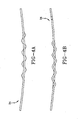
- FIGS 3 , 4A and 4B illustrate a blade 34 useful for manufacturing a sipe 26 of the type shown in FIG. 2 .
- the blade 34 has a defined thickness Wb, and has a pattern portion 36 that creates the multi-dimensional sipe 26 in a tire tread.
- the pattern portion 36 of the sipe blade 34 has a pattern depth Dp.
- the pattern portion 36 of the blade 34 itself has three defined portions 38, 40, 42.
- the first pattern portion 38 has a constant configuration and a constant effective pattern length Lpe for a depth D1 of at least 5% but not greater than 20% of the uppermost portion of the pattern depth Dp.
- the configuration for the first pattern portion 38 is preferably straight or has a slight curvature thereto.
- the constant configuration may also mimic the configuration of a groove that will be formed adjacent to the formed sipe.
- the second pattern portion 40 Directly adjacent to the first pattern portion 38 is a second pattern portion 40 best referred to as the transition zone.
- the second pattern portion 40 has a depth D2 of at least 5% but not greater than 25% of the pattern depth Dp.
- the configuration transforms from one constant configuration, that of the first pattern portion 38, to a second constant configuration, that of the third pattern portion 42, wherein along the entire depth of the second pattern portion 40, the effective length Lpe of the pattern is gradually increasing.
- the third and innermost pattern portion 42 Inward and directly adjacent to the second pattern portion 40 is the third and innermost pattern portion 42.
- the third pattern portion 42 has a depth D3 of at least 60% of the pattern depth, preferably, at least 75% of the pattern depth, but not more than 85% of the pattern depth.
- the pattern configuration is constant, with the effective length Lpe of the pattern portion 42 being constant, and the effective length Lpe being greater than the effective length Lpe of the first pattern portion 38.
- the effective length Lpe of the third pattern portion 42 is at least 110% greater than the effective length Lpe of the first pattern portion 38, and more preferably 120% greater than the effective length Lpe of the first pattern portion 38.
- the third pattern portion 42 has a zig-zag, crenellated, scalloped, or undulating configuration; FIG. 3 illustrates a zig-zag configuration for the third pattern portion 42.
- FIG. 4A is a top view of the blade 34 of FIG. 3 .
- the blade 34 has a slight curvature along the length of the blade. This curve extends along the length and depth of the blade 34 and creates a dominant pattern for the sipe blade and the sipe created therefrom.
- FIG. 4B is a bottom view of the same blade 34; again showing the dominant pattern of the curve that extends the depth of the blade 34. While this blade 34 is illustrated with a curve, as noted previously, the blade, and the sipe formed therefrom, may also have a straight configuration or one that mimics an adjacent groove being formed in the tire tread.
- all of the sipes 22 have a surface configuration that mimics the adjacent lateral grooves 14, 16, though not all of the illustrated sipes 22 may have a varying configuration in accordance with the invention.
- the selection of which sipes 22 are provided with a varying pattern along its depth is determined by numerous factors, including but not limited to, desired characteristics of the tire, ease of manufacturing the blade to make the sipe, and ease of manufacturing the tire using such a blade.
- An alternative tread configuration is illustrated in FIG. 5 .
- the surface configuration of a majority of the sipes 52 mimics an adjacent groove configuration and the non-mimicking sipes 54 have a straight or slightly curved configuration.
- the tire designer might select to form only sipes in the axially outermost tread element rows or the element row located on the equatorial plane of the tire with the disclosed dimensional sipe configuration.
- Sipes in accordance with the present invention provide for varying stiffness of the tread elements in which the sipes are formed during the tire tread life. Also, the increased effective length of the sipe as the sipe wears provides for more biting edges in the tire tread.
Landscapes
- Engineering & Computer Science (AREA)
- Mechanical Engineering (AREA)
- Tires In General (AREA)
- Moulds For Moulding Plastics Or The Like (AREA)
Claims (15)
- Reifen mit einer Reifenlauffläche (10), wobei die Reifenlauffläche eine Vielzahl von Rillen (12, 14, 16) umfasst, wobei die Rillen mindestens ein Profilelement bilden, wobei das Profilelement darin mindestens eine Lamelle (22) aufweist, wobei die Lamelle eine Breite (W), eine Lamellentiefe (Ds) und eine effektive Lamellenlänge (Le) aufweist, wobei die effektive Lamellenlänge (Le) berechnet wird als die Querschnittsfläche der Lamelle (22) an jeder Ebene senkrecht zu der Lamellentiefe (Ds), dividiert durch die Lamellentiefe (W), wobei die Lamelle (22) drei Lamellenteile (28, 30, 32) aufweist, wobei die drei Lamellenteile aus einem ersten, radial äußersten Teil (28) benachbart zu einer Außenfläche (24) der Reifenlauffläche, einem zweiten Übergangsteil (30) und einem dritten, radial innersten dritten Teil (32) benachbart zu einem radial innersten Punkt der Lamelle (22) bestehen,
dadurch gekennzeichnet, dass der erste, radial äußerste Lamellenteil (28) eine konstante effektive Lamellenlänge (Le) über die gesamte Tiefe des ersten Lamellenteils (28) aufweist, der zweite Übergangslamellenteil (30) eine allmählich zunehmende effektive Lamellenlänge (Le) über die gesamte Tiefe des zweiten Lamellenteils (30) aufweist und der dritte, radial innerste Lamellenteil (32) eine konstante effektive Lamellenlänge (Le) über die gesamte Tiefe des dritten, radial innersten Lamellenteils (28) aufweist. - Reifen nach Anspruch 1, wobei der erste Lamellenteil (28) eine Tiefe (D1) von mindestens 5% der Lamellentiefe (Ds) aufweist und/oder wobei der erste Lamellenteil (28) eine Tiefe (D1) von nicht mehr als 20% der Lamellentiefe (Ds) aufweist.
- Reifen nach Anspruch 1 oder 2, wobei der zweite Lamellenteil (30) eine Tiefe (D2) von mindestens 5% der Lamellentiefe (Ds) aufweist und/oder wobei der zweite Lamellenteil (30) eine Tiefe (D2) von nicht mehr als 25% der Lamellentiefe (Ds) aufweist.
- Reifen nach mindestens einem der vorgenannten Ansprüche, wobei der dritte Lamellenteil (32) eine Tiefe (D3) von mindestens 60% der Lamellentiefe (Ds) aufweist und/oder wobei der dritte Lamellenteil (32) eine Tiefe (D3) von nicht mehr als 85% der Lamellentiefe (Ds) aufweist.
- Reifen nach mindestens einem der vorgenannten Ansprüche, wobei der dritte Lamellenteil (32) eine effektive Lamellenlänge (Le) von mindestens 110% größer als die effektive Lamellenlänge (L3) des ersten Lamellenteils (28) aufweist.
- Reifen nach mindestens einem der vorgenannten Ansprüche, wobei der erste Lamellenteil (28) eine Konfiguration aufweist, die gerade ist, gekrümmt ist oder eine Konfiguration einer Rille nachahmt, die das Profilelement bildet, worin die Lamelle (26) ausgebildet ist.
- Reifen nach mindestens einem der vorgenannten Ansprüche, wobei die Lamelle (26) nur drei radial benachbarte Lamellenteile (28, 30, 32) über die vollständige Tiefe (Ds) der Lamelle (26) aufweist.
- Reifen nach mindestens einem der vorgenannten Ansprüche, wobei die Lamelle (26) nur den einen Übergangsteil (30) aufweist, wobei die effektive Länge (Le) der Lamelle (26) allmählich zunimmt.
- Reifen nach mindestens einem der vorgenannten Ansprüche, wobei der dritte Lamellenteil (32) eine Zickzack-, mit Zinnen versehene, gezahnte oder wellenförmige Konfiguration aufweist.
- Reifen nach Anspruch 1, wobei die effektive Lamellenlänge (Le) des dritten radial innersten Lamellenteils (32) größer als die effektive Lamellenlänge (Le) des ersten radial äußersten Lamellenteils (28) ist.
- Reifen nach Anspruch 1, wobei die drei Lamellenteile (28, 30, 32) einander in der aufgeführten Abfolge radial benachbart sind.
- Reifen nach Anspruch 1 oder 11, wobei die drei Lamellenteile (28, 30, 32) die einzigen Teile mit unterschiedlicher Konfiguration über die gesamte Tiefe der Lamelle (22) sind.
- Lamellenblech (34) zum Formen einer Lamelle (26) in einer Reifenlauffläche (10), wobei das Blech (34) eine Dicke (Wb) aufweist und einen Musterteil (36) aufweist, wobei der Musterteil eine Konfiguration hat, um eine Lamelle (26) mit einer entsprechenden Konfiguration zu formen, wobei der Musterteil (36) des Blechs (34) eine Mustertiefe (Dp) und eine effektive Musterlänge (Lpe) aufweist, wobei die effektive Musterlänge als die Querschnittsfläche des Musterteils (36) an jeder Ebene senkrecht zu der Mustertiefe (Dp), dividiert durch die Blechdicke (Wb), berechnet wird, wobei der Musterteil (36) des Blechs (34) drei Musterteile (38, 40, 42) aufweist, wobei die drei Musterteile aus einem ersten, obersten Musterteil (38), der den radial äußersten Teil (28) der Lamelle (22) bestimmt, einem zweiten Übergangsmusterteil (40) und einem dritten, untersten Musterteil (42), der den radial innersten Teil (32) der Lamelle (22) bestimmt, bestehen,
dadurch gekennzeichnet, dass der erste Musterteil (38) eine konstant effektive Musterlänge (Lpe) über die gesamte Tiefe des ersten, obersten Musterteils (38) aufweist, der zweite Übergangsmusterteil (40) eine allmählich zunehmende effektive Musterlänge (Lpe) über die gesamte Tiefe des zweiten Übergangsmusterteils (40) aufweist und der dritte, unterste Musterteil (42) eine konstante effektive Musterlänge (Lpe) über die gesamte Tiefe des dritten, untersten Musterteils (42) aufweist. - Lamellenblech nach Anspruch 13, wobei die effektive Musterlänge (Lpe) des dritten, untersten Musterteils (42) größer als die effektive Musterlänge (Lpe) des ersten, obersten Musterteils (38) ist.
- Lamellenblech nach Anspruch 13, wobei die drei Musterteile einander in der aufgeführten Abfolge radial benachbart sind und/oder die einzigen Teile mit unterschiedlichen Konfigurationen über die gesamte Tiefe der Lamelle (22) sind.
Applications Claiming Priority (1)
| Application Number | Priority Date | Filing Date | Title |
|---|---|---|---|
| US11/440,557 US20070272337A1 (en) | 2006-05-25 | 2006-05-25 | Pneumatic tire with tread siping |
Publications (2)
| Publication Number | Publication Date |
|---|---|
| EP1859962A1 EP1859962A1 (de) | 2007-11-28 |
| EP1859962B1 true EP1859962B1 (de) | 2009-07-08 |
Family
ID=38370801
Family Applications (1)
| Application Number | Title | Priority Date | Filing Date |
|---|---|---|---|
| EP07108692A Active EP1859962B1 (de) | 2006-05-25 | 2007-05-22 | Luftreifen mit Profilzuschneidung |
Country Status (7)
| Country | Link |
|---|---|
| US (1) | US20070272337A1 (de) |
| EP (1) | EP1859962B1 (de) |
| JP (1) | JP2007314168A (de) |
| KR (1) | KR20070113984A (de) |
| CN (1) | CN101085591A (de) |
| BR (1) | BRPI0702309A (de) |
| DE (1) | DE602007001490D1 (de) |
Cited By (1)
| Publication number | Priority date | Publication date | Assignee | Title |
|---|---|---|---|---|
| TWI453130B (zh) * | 2009-06-17 | 2014-09-21 | Sumitomo Rubber Ind | 崎嶇地行駛用充氣輪胎 |
Families Citing this family (28)
| Publication number | Priority date | Publication date | Assignee | Title |
|---|---|---|---|---|
| US7546861B2 (en) * | 2006-06-26 | 2009-06-16 | The Goodyear Tire & Rubber Company | Tire with tread having crossed configuration sipe |
| JP4211944B2 (ja) * | 2006-11-17 | 2009-01-21 | 東洋ゴム工業株式会社 | 空気入りタイヤ |
| DE102007059291A1 (de) * | 2007-12-08 | 2009-06-10 | Continental Aktiengesellschaft | Fahrzeugluftreifen |
| JP4438881B2 (ja) * | 2008-04-15 | 2010-03-24 | 横浜ゴム株式会社 | 空気入りタイヤ及びその製造方法、並びに、タイヤ加硫モールド |
| AU2009318659B2 (en) * | 2008-11-18 | 2011-08-25 | The Yokohama Rubber Co., Ltd. | Pneumatic tire |
| BRPI1008701A2 (pt) | 2009-02-18 | 2016-03-08 | Bridgestone Corp | pneumático |
| JP5756092B2 (ja) * | 2009-05-13 | 2015-07-29 | コンパニー ゼネラール デ エタブリッスマン ミシュラン | 薄くされた厚み部分をもつサイプを有するタイヤ及びその製造装置 |
| JP5562727B2 (ja) | 2010-06-01 | 2014-07-30 | 東洋ゴム工業株式会社 | 空気入りタイヤ |
| JP5432071B2 (ja) * | 2010-06-23 | 2014-03-05 | 東洋ゴム工業株式会社 | 空気入りタイヤ |
| JP5250016B2 (ja) * | 2010-11-12 | 2013-07-31 | 住友ゴム工業株式会社 | 空気入りタイヤ |
| US9616716B2 (en) | 2011-12-14 | 2017-04-11 | Bridgestone Americas Tire Operations, Llc | Three dimensional sipe |
| JP2014125102A (ja) * | 2012-12-26 | 2014-07-07 | Toyo Tire & Rubber Co Ltd | 空気入りタイヤ |
| US9463672B2 (en) * | 2013-08-20 | 2016-10-11 | The Goodyear Tire & Rubber Company | Pneumatic tire tread with sipes and mold blade |
| US9999274B2 (en) * | 2013-10-10 | 2018-06-19 | Cole Haan Llc | Shoe having multiple sole members |
| JP5971280B2 (ja) * | 2014-06-02 | 2016-08-17 | 横浜ゴム株式会社 | 空気入りタイヤ |
| KR101898453B1 (ko) * | 2014-09-05 | 2018-09-13 | 요코하마 고무 가부시키가이샤 | 공기입 타이어 |
| US10899178B2 (en) * | 2014-09-05 | 2021-01-26 | The Yokohama Rubber Co., Ltd. | Pneumatic tire |
| CN105539018A (zh) * | 2015-12-22 | 2016-05-04 | 赛轮金宇集团股份有限公司 | 一种卡客车轮胎的钢片及使用该钢片制造的轮胎 |
| EP3335909B1 (de) * | 2016-12-19 | 2021-10-13 | Nokian Renkaat Oyj | Luftreifen, lauffläche und profilblock mit einer lamelle und lamellenplatte zur herstellung davon |
| IT201800003994A1 (it) | 2018-03-27 | 2019-09-27 | Bridgestone Europe Nv Sa | Battistrada per pneumatico e pneumatico |
| EP3549793B1 (de) | 2018-04-06 | 2021-02-24 | Sumitomo Rubber Industries, Ltd. | Reifen |
| JP7144309B2 (ja) * | 2018-12-19 | 2022-09-29 | 株式会社ブリヂストン | 加硫成形用金型 |
| JP7363453B2 (ja) | 2019-12-19 | 2023-10-18 | 住友ゴム工業株式会社 | 空気入りタイヤ |
| JP7136169B2 (ja) * | 2020-11-20 | 2022-09-13 | 横浜ゴム株式会社 | タイヤ |
| US12122113B2 (en) | 2021-02-03 | 2024-10-22 | Bridgestone Bandag, Llc | Versatile sipe machine |
| DE102021209584A1 (de) * | 2021-09-01 | 2023-03-02 | Continental Reifen Deutschland Gmbh | Fahrzeugluftreifen |
| JP7812445B2 (ja) * | 2021-12-06 | 2026-02-09 | ブリヂストン アメリカズ タイヤ オペレーションズ、 エルエルシー | 双方向インターロッキングサイプとスロットの組み合わせ |
| USD1063809S1 (en) | 2023-10-16 | 2025-02-25 | Bridgestone Bandag, Llc | Tire |
Family Cites Families (12)
| Publication number | Priority date | Publication date | Assignee | Title |
|---|---|---|---|---|
| JPS63195006A (ja) * | 1987-02-09 | 1988-08-12 | Yokohama Rubber Co Ltd:The | 空気入りタイヤ |
| FR2722144B1 (fr) * | 1994-07-05 | 1996-09-27 | Michelin & Cie | Bande de roulement pour pneumatique |
| JP3499995B2 (ja) * | 1995-12-29 | 2004-02-23 | 住友ゴム工業株式会社 | 空気入りタイヤ |
| JPH11151914A (ja) * | 1997-11-20 | 1999-06-08 | Bridgestone Corp | 空気入りタイヤ |
| JPH11165507A (ja) * | 1997-12-03 | 1999-06-22 | Bridgestone Corp | 空気入りタイヤ |
| DE19812778C2 (de) * | 1998-03-24 | 2002-07-04 | Continental Ag | Hochstabile Lamelle, Vulkanisationsform mit solchen Lamellen, Fahrzeugreifen mit Lauffläche, in die Einschnitte mittels solcher Lamellen gebracht sind |
| US6427737B1 (en) | 1998-04-22 | 2002-08-06 | Bridgestone Corporation | Pneumatic tire having at least four sipes |
| JP3648179B2 (ja) * | 2001-07-18 | 2005-05-18 | 住友ゴム工業株式会社 | 空気入りタイヤ及びその加硫金型 |
| FR2871735B1 (fr) * | 2004-06-16 | 2006-08-04 | Michelin Soc Tech | Bande de roulement ayant des incisions zigzag et lames pour le moulage de telles incisions |
| JP3791926B2 (ja) * | 2004-07-21 | 2006-06-28 | 横浜ゴム株式会社 | 空気入りタイヤ |
| USD515018S1 (en) * | 2005-04-12 | 2006-02-14 | The Goodyear Tire & Rubber Company | Tire tread |
| USD515019S1 (en) * | 2005-04-12 | 2006-02-14 | The Goodyear Tire & Rubber Company | Tire tread |
-
2006
- 2006-05-25 US US11/440,557 patent/US20070272337A1/en not_active Abandoned
-
2007
- 2007-05-15 JP JP2007128689A patent/JP2007314168A/ja active Pending
- 2007-05-21 BR BRPI0702309-0A patent/BRPI0702309A/pt not_active Application Discontinuation
- 2007-05-22 DE DE602007001490T patent/DE602007001490D1/de active Active
- 2007-05-22 EP EP07108692A patent/EP1859962B1/de active Active
- 2007-05-22 KR KR1020070049610A patent/KR20070113984A/ko not_active Ceased
- 2007-05-25 CN CNA2007101045616A patent/CN101085591A/zh active Pending
Cited By (1)
| Publication number | Priority date | Publication date | Assignee | Title |
|---|---|---|---|---|
| TWI453130B (zh) * | 2009-06-17 | 2014-09-21 | Sumitomo Rubber Ind | 崎嶇地行駛用充氣輪胎 |
Also Published As
| Publication number | Publication date |
|---|---|
| BRPI0702309A (pt) | 2008-03-04 |
| US20070272337A1 (en) | 2007-11-29 |
| CN101085591A (zh) | 2007-12-12 |
| DE602007001490D1 (de) | 2009-08-20 |
| KR20070113984A (ko) | 2007-11-29 |
| EP1859962A1 (de) | 2007-11-28 |
| JP2007314168A (ja) | 2007-12-06 |
Similar Documents
| Publication | Publication Date | Title |
|---|---|---|
| EP1859962B1 (de) | Luftreifen mit Profilzuschneidung | |
| EP1616719B1 (de) | Luftreifen | |
| US7143799B2 (en) | Three-dimensional sipes for treads | |
| EP0450251B1 (de) | Lauffläche für Luftreifen | |
| EP1935671B1 (de) | Luftreifen | |
| EP1073562B1 (de) | Reifenlauffläche mit 3-d lamellen | |
| US7793692B2 (en) | Pneumatic tire tread having sipe that devolves into groove as tread wears | |
| EP1623818B1 (de) | 3-D Laufflächefeineinschnitte und Lamelle zur Gestalltung solcher Feineinschnitte | |
| CN102985267B (zh) | 胎面保护装置 | |
| JP2008007102A (ja) | サイプを備えたトレッドを有するタイヤ、及びタイヤ用のサイプブレード | |
| CN102442163A (zh) | 加强轮胎胎面 | |
| EP1935670B1 (de) | Luftreifen | |
| KR20070122402A (ko) | 타이어 | |
| EP1676727B1 (de) | Reifenlauffläche mit hinterschnittenen Profilelementen | |
| EP1872975B1 (de) | Reifenlauffläche mit Feineinschnitten und Lamelle für Reifenvulkanisierungsform | |
| EP1872976B1 (de) | Luftreifen mit Feineinschnitten einer bestimmten Krümmung | |
| CN121001885A (zh) | 具有改进的胎面花纹的轮胎 |
Legal Events
| Date | Code | Title | Description |
|---|---|---|---|
| PUAI | Public reference made under article 153(3) epc to a published international application that has entered the european phase |
Free format text: ORIGINAL CODE: 0009012 |
|
| AK | Designated contracting states |
Kind code of ref document: A1 Designated state(s): AT BE BG CH CY CZ DE DK EE ES FI FR GB GR HU IE IS IT LI LT LU LV MC MT NL PL PT RO SE SI SK TR |
|
| AX | Request for extension of the european patent |
Extension state: AL BA HR MK YU |
|
| 17P | Request for examination filed |
Effective date: 20080528 |
|
| 17Q | First examination report despatched |
Effective date: 20080627 |
|
| AKX | Designation fees paid |
Designated state(s): DE FR IT PL |
|
| GRAP | Despatch of communication of intention to grant a patent |
Free format text: ORIGINAL CODE: EPIDOSNIGR1 |
|
| GRAS | Grant fee paid |
Free format text: ORIGINAL CODE: EPIDOSNIGR3 |
|
| GRAA | (expected) grant |
Free format text: ORIGINAL CODE: 0009210 |
|
| AK | Designated contracting states |
Kind code of ref document: B1 Designated state(s): DE FR IT PL |
|
| REF | Corresponds to: |
Ref document number: 602007001490 Country of ref document: DE Date of ref document: 20090820 Kind code of ref document: P |
|
| PG25 | Lapsed in a contracting state [announced via postgrant information from national office to epo] |
Ref country code: PL Free format text: LAPSE BECAUSE OF FAILURE TO SUBMIT A TRANSLATION OF THE DESCRIPTION OR TO PAY THE FEE WITHIN THE PRESCRIBED TIME-LIMIT Effective date: 20090708 |
|
| PLBE | No opposition filed within time limit |
Free format text: ORIGINAL CODE: 0009261 |
|
| STAA | Information on the status of an ep patent application or granted ep patent |
Free format text: STATUS: NO OPPOSITION FILED WITHIN TIME LIMIT |
|
| 26N | No opposition filed |
Effective date: 20100409 |
|
| PG25 | Lapsed in a contracting state [announced via postgrant information from national office to epo] |
Ref country code: IT Free format text: LAPSE BECAUSE OF NON-PAYMENT OF DUE FEES Effective date: 20100522 |
|
| REG | Reference to a national code |
Ref country code: FR Ref legal event code: PLFP Year of fee payment: 10 |
|
| REG | Reference to a national code |
Ref country code: FR Ref legal event code: PLFP Year of fee payment: 11 |
|
| REG | Reference to a national code |
Ref country code: FR Ref legal event code: PLFP Year of fee payment: 12 |
|
| REG | Reference to a national code |
Ref country code: FR Ref legal event code: PLFP Year of fee payment: 17 |
|
| PGFP | Annual fee paid to national office [announced via postgrant information from national office to epo] |
Ref country code: DE Payment date: 20250423 Year of fee payment: 19 |
|
| PGFP | Annual fee paid to national office [announced via postgrant information from national office to epo] |
Ref country code: IT Payment date: 20250423 Year of fee payment: 19 |
|
| PGFP | Annual fee paid to national office [announced via postgrant information from national office to epo] |
Ref country code: FR Payment date: 20250424 Year of fee payment: 19 |