EP1859968B1 - Elektronisches bauelement und reifen - Google Patents
Elektronisches bauelement und reifen Download PDFInfo
- Publication number
- EP1859968B1 EP1859968B1 EP06715607A EP06715607A EP1859968B1 EP 1859968 B1 EP1859968 B1 EP 1859968B1 EP 06715607 A EP06715607 A EP 06715607A EP 06715607 A EP06715607 A EP 06715607A EP 1859968 B1 EP1859968 B1 EP 1859968B1
- Authority
- EP
- European Patent Office
- Prior art keywords
- antenna
- tyre
- signal line
- electronic device
- rim wheel
- Prior art date
- Legal status (The legal status is an assumption and is not a legal conclusion. Google has not performed a legal analysis and makes no representation as to the accuracy of the status listed.)
- Ceased
Links
- 239000004020 conductor Substances 0.000 claims abstract description 7
- 239000000758 substrate Substances 0.000 abstract description 11
- 239000011324 bead Substances 0.000 description 6
- 239000003990 capacitor Substances 0.000 description 5
- 230000002238 attenuated effect Effects 0.000 description 4
- -1 polyethylene Polymers 0.000 description 3
- XEEYBQQBJWHFJM-UHFFFAOYSA-N Iron Chemical compound [Fe] XEEYBQQBJWHFJM-UHFFFAOYSA-N 0.000 description 2
- 239000004698 Polyethylene Substances 0.000 description 2
- 229910000831 Steel Inorganic materials 0.000 description 2
- 239000006096 absorbing agent Substances 0.000 description 2
- 239000012212 insulator Substances 0.000 description 2
- 229920000573 polyethylene Polymers 0.000 description 2
- 230000035939 shock Effects 0.000 description 2
- 239000010959 steel Substances 0.000 description 2
- RYGMFSIKBFXOCR-UHFFFAOYSA-N Copper Chemical compound [Cu] RYGMFSIKBFXOCR-UHFFFAOYSA-N 0.000 description 1
- 239000004743 Polypropylene Substances 0.000 description 1
- 239000004793 Polystyrene Substances 0.000 description 1
- BZHJMEDXRYGGRV-UHFFFAOYSA-N Vinyl chloride Chemical compound ClC=C BZHJMEDXRYGGRV-UHFFFAOYSA-N 0.000 description 1
- XAGFODPZIPBFFR-UHFFFAOYSA-N aluminium Chemical compound [Al] XAGFODPZIPBFFR-UHFFFAOYSA-N 0.000 description 1
- 229910052782 aluminium Inorganic materials 0.000 description 1
- 229910052802 copper Inorganic materials 0.000 description 1
- 239000010949 copper Substances 0.000 description 1
- 230000001419 dependent effect Effects 0.000 description 1
- 239000000945 filler Substances 0.000 description 1
- 229910052742 iron Inorganic materials 0.000 description 1
- 239000007769 metal material Substances 0.000 description 1
- 239000004033 plastic Substances 0.000 description 1
- 229920003023 plastic Polymers 0.000 description 1
- 229920001155 polypropylene Polymers 0.000 description 1
- 229920002223 polystyrene Polymers 0.000 description 1
- 229920000915 polyvinyl chloride Polymers 0.000 description 1
- 239000004800 polyvinyl chloride Substances 0.000 description 1
Images


Classifications
-
- B—PERFORMING OPERATIONS; TRANSPORTING
- B60—VEHICLES IN GENERAL
- B60C—VEHICLE TYRES; TYRE INFLATION; TYRE CHANGING; CONNECTING VALVES TO INFLATABLE ELASTIC BODIES IN GENERAL; DEVICES OR ARRANGEMENTS RELATED TO TYRES
- B60C23/00—Devices for measuring, signalling, controlling, or distributing tyre pressure or temperature, specially adapted for mounting on vehicles; Arrangement of tyre inflating devices on vehicles, e.g. of pumps or of tanks; Tyre cooling arrangements
- B60C23/02—Signalling devices actuated by tyre pressure
- B60C23/04—Signalling devices actuated by tyre pressure mounted on the wheel or tyre
- B60C23/0408—Signalling devices actuated by tyre pressure mounted on the wheel or tyre transmitting the signals by non-mechanical means from the wheel or tyre to a vehicle body mounted receiver
-
- B—PERFORMING OPERATIONS; TRANSPORTING
- B60—VEHICLES IN GENERAL
- B60C—VEHICLE TYRES; TYRE INFLATION; TYRE CHANGING; CONNECTING VALVES TO INFLATABLE ELASTIC BODIES IN GENERAL; DEVICES OR ARRANGEMENTS RELATED TO TYRES
- B60C23/00—Devices for measuring, signalling, controlling, or distributing tyre pressure or temperature, specially adapted for mounting on vehicles; Arrangement of tyre inflating devices on vehicles, e.g. of pumps or of tanks; Tyre cooling arrangements
- B60C23/02—Signalling devices actuated by tyre pressure
- B60C23/04—Signalling devices actuated by tyre pressure mounted on the wheel or tyre
- B60C23/0491—Constructional details of means for attaching the control device
- B60C23/0494—Valve stem attachments positioned inside the tyre chamber
Definitions
- the present invention relates to an electronic device capable of transmitting information by radio and also relates to a tyre.
- electronic devices such as a sensor for measuring an air pressure (internal pressure) of the compressed air that fills up a tyre and a transmitter for transmitting radio waves containing information measured by that sensor to a wheel side have been arranged inside a tyre, or more specifically, in a space partitioned by a tyre and a rim wheel (a partitioned space, hereafter).
- an electronic device 7 is arranged between an inner liner 6 positioned inside a belt layer in a radial direction of a tyre 1 and that belt layer.
- an air valve 21 attached to a rim wheel 22 and an electronic device 10 are set in an integrated form such that a pressure or the like of the compressed air that fills up a tyre can be measured.
- an antenna 14 is positioned inside the partitioned space.
- a tyre various metallic materials (wire cords and steel cords, for example) are used for portions (a bead portion and a carcass layer, for example) constituting that tyre, and in a rim wheel, iron, aluminum or the like is used, so that the radio waves transmitted by the electronic device will be attenuated by repeating reflections in the partitioned space.
- an antenna 16 is directly projected outside at a position close from an air control valve 10, rather than piercing the antenna 16 through the air control valve 10.
- an LC resonance L: coil, C: capacitor
- a circuit for matching the antenna 16 such as a resistance capacitor and a coil.
- insulative grommets 19, 20 are disclosed. However, these insulative grommets 19, 20 are insufficient for high frequencies, so that the LC resonance cannot be prevented completely.
- the present invention has been achieved in view of the above described problems, and has an object to provide an electronic device attached to a rim wheel which is capable of transmitting high precision radio waves which will not be reflected in the partitioned space.
- An electronic device attached to a rim wheel according to the first aspect of the present invention is provided having the features of claim 1.
- An electronic device attached to a rim wheel according to the second aspect of the present invention is provided having the features of claim 3.
- Preferred embodiments of the present invention are the subject matter of the dependent claims.
- Fig. 1 is a cross sectional view in a tread width direction of a tyre 1 and a rim wheel 2 according to the first embodiment.
- the tyre 1 has a pair of bead portions 11 containing a bead core 11b and a bead filler 11a. More specifically, for the bead core 11b that constitutes the bead portion 11, a steel cord or the like is used.
- the tyre 1 has a carcass layer 12 which becomes a framework of that tyre 1. Also, on an inner side in a tyre radial direction of the carcass layer 12, an inner liner 13 which is a rubber layer with a high airtightness and serves as a tube is provided.
- a belt layer 14 is arranged on an outer side in a tyre radial direction of the carcass layer 12. More specifically, the belt layer 14 comprises a first belt layer 14a positioned on an outer side in a tyre radial direction of the carcass layer 12, and a second belt layer 14b positioned on an outer side in a tyre radial direction of that first belt layer 14a.
- a tread portion 15 to contact a road surface is arranged on an outer side in a tyre radial direction of the belt layer 14.
- the above described structural elements are substantially left and right symmetrical with respect to a center line CL of Fig. 1 .
- an air valve 30 for pouring air into a space partitioned by the tyre 1 and the rim wheel 2 (a partitioned space 10, hereafter) is provided.
- an electronic device 40 is attached on the partitioned space 10 side of this air valve 30, an electronic device 40 is attached.
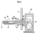
- the electronic device 40 comprises a transmitter substrate 43 (generation unit) for generating information of the tyre (an inner pressure of the tyre, for example) to be measured by a sensor arranged in the partitioned space 10, a signal line 45 extended from that transmitter substrate 43 to outside of the partitioned space 10 (namely, outside of the tyre 1) and passing through inside the air valve 30, and an antenna 47 connected to that signal line 45 and positioned outside the air valve 30.
- a hole of the rim wheel 2 is closed by a plug 60.
- This signal line 45 is formed by a core wire 45a made of a conductor and a coaxial cable 45b covering that core wire 45a. More specifically, the coaxial cable 45b is such that the core wire 45a is wrapped by an insulator or a shock absorber such as polyethylene, an outer side (circumference) of the insulator or the shock absorber is covered by a net shaped shield layer made of knitted copper wires, and further an outer side of the shield layer is covered by a vinyl chloride or the like.
- the antenna 47 is extending substantially in parallel to a straight line portion 32 having a straight line shape of the air valve 30.
- a tuning circuit 49 in which a capacitor and a coil are connected in series is provided, in order to prevent the attenuation of radio waves transmitted from the transmitter substrate 43 (to transmit high precision radio waves).
- the antenna 47 is positioned outside the air valve 30, so that the electronic device 40 can transmit the high precision radio waves which will not be reflected in the partitioned space 10.
- the electronic device 40 has the signal line 45 formed by the core wire 45a made of a conductor and the coaxial cable 45b covering that core wire 45a, so that the reflection of the radio waves between the signal lines 45, that is the reflection of the radio waves in the partitioned space 10 and inside the air valve 30, can be prevented (the radio waves will not be attenuated).
- the antenna 47 is positioned outside the air valve 30, so that the electronic device 40 can transmit the high precision radio waves which will not be reflected in that partitioned space 10 and inside the air valve 30.
- the tuning circuit 49 is provided at a connecting portion of the signal line 45 and the antenna 47, so that the attenuation of the radio waves transmitted from the transmitter substrate 43 can be prevented (the high precision radio waves can be transmitted).
- the antenna 47 is placed outside the partitioned space 10 (namely, outside of the tyre 1) by using the coaxial cable 45b inside the plug 60, so that the LC resonance (L: coil, C: capacitor) is avoided.
- the electronic device 40 described above is transmitting information of the tyre to the wheel side through the signal line 45 positioned inside the air valve 30 and the antenna 47 positioned outside the air valve 30.
- the signal line 45 and the antenna 47 to be described below are arranged in a region other than the air valve 30 provided on the rim wheel 2.
- the signal line 45 is extended from the transmitter substrate 43 through the rim wheel 2 to outside of the partitioned space 10 (namely, outside of the tyre 1).
- This signal line 45 is formed by the core wire 45a made of a conductor and the coaxial cable 45b covering that core wire 45a.
- the antenna 47 is positioned outside the partitioned space 10 and connected to the core wire 45a. Also, it is preferable to arrange an antenna guard 48 for directly covering the antenna 47 (namely, covering the antenna 47 by making contact with the antenna 47).
- an antenna guard 48 plastics (polyethylene, polyvinyl chloride, polystyrene, polypropylene, for example) are used.
- the tuning circuit 49 in which a capacitor and a coil are connected in series is provided, in order to prevent the attenuation of radio waves transmitted from the transmitter substrate 43 (to transmit high precision radio waves).
- the antenna 47 is positioned outside the tyre 1 (outside of the partitioned space 10), so that the electronic device 40 can transmit the high precision radio waves which will not be reflected in the partitioned space 10.
- the electronic device 40 has the signal line 45 formed by the core wire 45a made of a conductor and the coaxial cable 45b covering that core wire 45a, so that the reflection of the radio waves between the signal lines 45, that is the reflection of the radio waves in the partitioned space 10 and inside the air valve 30, can be prevented (the radio waves will not be attenuated).
- the antenna 47 is positioned outside the partitioned space 10, so that the electronic device 40 can transmit the high precision radio waves which will not be reflected in that partitioned space 10 and inside the air valve 30.
- the tuning circuit 49 is provided at a connecting portion of the signal line 45 and the antenna 47, so that the attenuation of the radio waves transmitted from the transmitter substrate 43 can be prevented (the high precision radio waves can be transmitted).
- the antenna guard 48 for directly covering the antenna 47 is provided, so that the antenna can be reinforced and that antenna can be protected.
- the antenna 47 is placed outside the partitioned space 10 (namely, outside of the tyre 1) by using the coaxial cable 45b inside the plug 60, so that the LC resonance is avoided.
- the radio waves emitted out of the partitioned space 10 have the size equivalent to that of the radio waves transmitted by the transmitter substrate 43. Namely, matching the impedance by using the coaxial cable 45b which is shielded so as not to receive the influence of the high frequency can carry out the efficient communications. Consequently, it is possible to provide the electronic device 40 that can transmit the high precision radio waves which will not be reflected in the partitioned space 10, and the tyre 1 on which that electronic device 40 is provided.
- the electronic device that can transmit the high precision radio waves which will not be reflected in the partitioned space, and the tyre on which that electronic device is provided.
Landscapes
- Engineering & Computer Science (AREA)
- Mechanical Engineering (AREA)
- Arrangements For Transmission Of Measured Signals (AREA)
- Measuring Fluid Pressure (AREA)
Claims (4)
- Felgenrad (2), das an einem Reifen befestigt ist, bei dem ein elektronisches Bauelement (40) vorhanden ist, das eine Information mittels Funk übertragen kann, wobei das elektronische Bauelement aufweist:eine Erzeugungsanlage (43) für das Erzeugen einer Information, die von einem Sensor gemessen wird, der in einem abgeteilten Raum (10) angeordnet ist, der durch den Reifen (1) und das am Reifen (1) befestigte Felgenrad (2) abgeteilt wird;eine Antenne (47) für das Übertragen von Funkwellen, die die von der Erzeugungsanlage (43) erzeugte Information enthält,gekennzeichnet durcheine Signalleitung (45), die sich von der Erzeugungsanlage (43) zur Außenseite des abgeteilten Raumes (10) erstreckt und durch eine Innenseite des Luftventils (30) führt, das am Felgenrad (2) vorhanden ist, und wobeidie Signalleitung (45) mittels eines Kerndrahtes (45a), der aus einem Leiter besteht, und einem Koaxialkabel (45b) gebildet wird, das den Kerndraht (45a) bedeckt, unddie Antenne (47) außerhalb des Luftventils (30) positioniert und die Antenne (47) mit der Signalleitung (45) verbunden ist.
- Felgenrad nach Anspruch 1, bei dem ein Abstimmkreis (49) im Verbindungsabschnitt der Signalleitung (45) und der Antenne (47) vorhanden ist.
- Felgenrad (2), das an einem Reifen befestigt ist, bei dem ein elektronisches Bauelement (40) vorhanden ist, das eine Information mittels Funk übertragen kann, wobei das elektronische Bauelement aufweist:eine Erzeugungsanlage (43) für das Erzeugen einer Information, die von einem Sensor gemessen wird, der in einem abgeteilten Raum (10) angeordnet ist, der durch den Reifen (1) und das mit dem Reifen (1) versehene Felgenrad (2) abgeteilt wird;eine Antenne (47) für das Übertragen von Funkwellen, die die von der Erzeugungsanlage (43) erzeugte Information enthält,gekennzeichnet durcheine Signalleitung (45), die sich von der Erzeugungsanlage (43) zur Außenseite des abgeteilten Raumes (10) erstreckt, und wobeidie Signalleitung (45) mittels eines Kerndrahtes (45a), der aus einem Leiter besteht, und einem Koaxialkabel (45b) gebildet wird, das den Kerndraht (45a) bedeckt, unddie Antenne (47) mit der Signalleitung (45) verbunden ist, unddie Signalleitung (45) und die Antenne (47) mit einem Antennenschutz (48) bedeckt sind, der sich vom abgeteilten Raum (10) zur Außenseite des abgeteilten Raumes (10) erstreckt.
- Felgenrad nach Anspruch 3, bei dem ein Abstimmkreis (49) im Verbindungsabschnitt der Signalleitung (45) und der Antenne (47) vorhanden ist.
Applications Claiming Priority (2)
| Application Number | Priority Date | Filing Date | Title |
|---|---|---|---|
| JP2005071460 | 2005-03-14 | ||
| PCT/JP2006/304884 WO2006098265A1 (ja) | 2005-03-14 | 2006-03-13 | 電子デバイス及びタイヤ |
Publications (3)
| Publication Number | Publication Date |
|---|---|
| EP1859968A1 EP1859968A1 (de) | 2007-11-28 |
| EP1859968A4 EP1859968A4 (de) | 2010-07-28 |
| EP1859968B1 true EP1859968B1 (de) | 2011-12-21 |
Family
ID=36991607
Family Applications (1)
| Application Number | Title | Priority Date | Filing Date |
|---|---|---|---|
| EP06715607A Ceased EP1859968B1 (de) | 2005-03-14 | 2006-03-13 | Elektronisches bauelement und reifen |
Country Status (4)
| Country | Link |
|---|---|
| US (1) | US7642905B2 (de) |
| EP (1) | EP1859968B1 (de) |
| JP (1) | JPWO2006098265A1 (de) |
| WO (1) | WO2006098265A1 (de) |
Families Citing this family (4)
| Publication number | Priority date | Publication date | Assignee | Title |
|---|---|---|---|---|
| EP2602130A1 (de) * | 2011-12-09 | 2013-06-12 | Josn Electronic Co., Ltd. | Reifendrucküberwachungsvorrichtung |
| DE102014205922B4 (de) * | 2014-03-31 | 2020-12-03 | Aktiebolaget Skf | Modul zum Erfassen eines Vibrationsverhaltens einer mechanischen Komponente |
| US11247515B2 (en) * | 2016-11-23 | 2022-02-15 | Christopher Scott Larsen | Apparatus for wheel-mounted wireless measurement of tire pressure and method for doing the same |
| US11735859B2 (en) | 2020-05-29 | 2023-08-22 | Pacific Industrial Co., Ltd. | Connector and connector manufacturing method |
Family Cites Families (23)
| Publication number | Priority date | Publication date | Assignee | Title |
|---|---|---|---|---|
| US2894246A (en) * | 1957-05-06 | 1959-07-07 | Raymond J Stockholm | Tire alarm system |
| US4048614A (en) * | 1975-08-18 | 1977-09-13 | Shumway Harry J | Low tire pressure warning device |
| JP3335846B2 (ja) * | 1996-08-06 | 2002-10-21 | 太平洋工業株式会社 | タイヤ空気圧警報装置 |
| JPH1178447A (ja) * | 1997-09-04 | 1999-03-23 | Hino Motors Ltd | タイヤ空気圧警報装置 |
| US6101870A (en) * | 1997-11-10 | 2000-08-15 | Pacific Industrial Co., Ltd. | Tire air pressure monitoring device using the wheel or a coil wound around the stem as the transmitter antenna |
| JP3354857B2 (ja) * | 1997-12-17 | 2002-12-09 | 太平洋工業株式会社 | タイヤ空気圧警報装置 |
| JP3304862B2 (ja) * | 1997-12-08 | 2002-07-22 | 太平洋工業株式会社 | タイヤ空気圧警報装置 |
| US5977870A (en) | 1997-12-22 | 1999-11-02 | Bridgestone/Firestone, Inc. | Method and apparatus for transmitting stored data and engineering conditions of a tire to a remote location |
| US6340929B1 (en) * | 1998-11-19 | 2002-01-22 | Pacific Industrial Co., Ltd | Transmitter and external controller of tire inflation pressure monitor |
| JP3354887B2 (ja) * | 1998-12-17 | 2002-12-09 | 太平洋工業株式会社 | タイヤ空気圧警報装置の送信機 |
| JP3392364B2 (ja) * | 1998-12-21 | 2003-03-31 | 太平洋工業株式会社 | タイヤ空気圧警報装置 |
| ATE239623T1 (de) | 1999-02-11 | 2003-05-15 | Emtop Ltd | Signalübertragungsvorrichtung und -verfahren, sensorvorrichtung und reifendruckmessvorrichtung mit einer solchen signalübertragungsvorrichtung |
| GB2383415B (en) | 2000-09-08 | 2005-02-23 | Automotive Tech Int | Vehicle wireless sensing and communication system |
| JP2002264621A (ja) * | 2001-03-12 | 2002-09-18 | Pacific Ind Co Ltd | タイヤ状態監視装置の送信機 |
| US6799455B1 (en) * | 2001-08-09 | 2004-10-05 | Edward F. Neefeldt | Vehicle tire air monitor |
| DE10148876B4 (de) * | 2001-10-04 | 2005-11-03 | Siemens Ag | Vorrichtung zum Messen eines Reifendrucks |
| JP2003146033A (ja) | 2001-11-15 | 2003-05-21 | Bridgestone Corp | タイヤ内圧警報装置 |
| JP2003165313A (ja) * | 2001-11-28 | 2003-06-10 | Pacific Ind Co Ltd | タイヤ状態監視装置 |
| GB0211663D0 (en) * | 2002-05-21 | 2002-07-03 | Transense Technologies Plc | Tyre sensor interrogation |
| JP4204845B2 (ja) | 2002-10-30 | 2009-01-07 | 株式会社ブリヂストン | 電子チップを配設した空気入りタイヤおよびその製造方法 |
| AU2002952723A0 (en) * | 2002-11-18 | 2002-12-05 | Phillip Albert Cohen | Improvements in tyre pressure and temperature monitoring systems |
| JP2005186658A (ja) | 2003-12-24 | 2005-07-14 | Chuo Motor Wheel Co Ltd | タイヤ空気圧検知手段を備えたタイヤバルブ及び該バルブを備えたタイヤ空気圧検知装置 |
| JP2006131027A (ja) * | 2004-11-04 | 2006-05-25 | Toyota Motor Corp | 車輪情報処理装置およびバランスウエイト |
-
2006
- 2006-03-13 EP EP06715607A patent/EP1859968B1/de not_active Ceased
- 2006-03-13 US US11/886,316 patent/US7642905B2/en not_active Expired - Fee Related
- 2006-03-13 WO PCT/JP2006/304884 patent/WO2006098265A1/ja not_active Ceased
- 2006-03-13 JP JP2007508119A patent/JPWO2006098265A1/ja active Pending
Also Published As
| Publication number | Publication date |
|---|---|
| JPWO2006098265A1 (ja) | 2008-08-21 |
| US7642905B2 (en) | 2010-01-05 |
| EP1859968A4 (de) | 2010-07-28 |
| WO2006098265A1 (ja) | 2006-09-21 |
| US20090009312A1 (en) | 2009-01-08 |
| EP1859968A1 (de) | 2007-11-28 |
Similar Documents
| Publication | Publication Date | Title |
|---|---|---|
| AU2016323529B2 (en) | Tyre comprising a passive transponder and method for reading the data | |
| EP1580041B1 (de) | Funkantenne für Reifen und Verfahren hierzu | |
| US8593357B2 (en) | Tyre having a member with an offset antenna | |
| CN103025545B (zh) | 具有信息取得装置的轮胎 | |
| JP5264974B2 (ja) | 無接点電力伝送装置 | |
| JP2004001716A (ja) | 受信アンテナ付きタイヤ | |
| WO2007069367A1 (ja) | アンテナ装置 | |
| US7642905B2 (en) | Electronic device and tyre | |
| CA2968003C (en) | Broadband antenna in the crash pad for vehicle | |
| EP1506100B1 (de) | Reifenüberwachung und ventil dafür | |
| CN112864629B (zh) | 辐射同轴线缆 | |
| CN104015576B (zh) | 蓝牙胎压发送器天线 | |
| JP2005136937A (ja) | 放射型漏洩同軸ケーブルを用いたタイヤ空気圧警報装置の受信アンテナ | |
| Enalume et al. | Design and analysis of a 2.4 GHz whip antenna for tyre pressure monitoring system | |
| Dinh et al. | FEKO-based method for electromagnetic simulation of carcass wires embedded in vehicle tires | |
| JP6988724B2 (ja) | 挟み込みセンサおよび検出装置 | |
| JP5028773B2 (ja) | 空気入りタイヤ及びタイヤ・ホイール組立体 | |
| JP5506607B2 (ja) | シールド部材の異常検出方法及びシールド部材の異常検出装置 | |
| FI89754C (fi) | Antenn | |
| JP2004326158A (ja) | タイヤ装着用センサ装置及びセンサ装着タイヤ | |
| CN212654148U (zh) | 一体化集成的胎压监测传感器和轮胎 | |
| Rida et al. | Evaluation of TPMS Signal Propagation in a Heavy Commercial Vehicle Environement | |
| JP2025535913A (ja) | 輸送車両に搭載される無線周波数読み取りシステム | |
| CN117715770A (zh) | 运输工具上的射频读取系统 | |
| CN106935980A (zh) | 传输发射不同频段射频信号的喇叭形天线 |
Legal Events
| Date | Code | Title | Description |
|---|---|---|---|
| PUAI | Public reference made under article 153(3) epc to a published international application that has entered the european phase |
Free format text: ORIGINAL CODE: 0009012 |
|
| 17P | Request for examination filed |
Effective date: 20070921 |
|
| AK | Designated contracting states |
Kind code of ref document: A1 Designated state(s): DE FR IT |
|
| DAX | Request for extension of the european patent (deleted) | ||
| RBV | Designated contracting states (corrected) |
Designated state(s): DE FR IT |
|
| A4 | Supplementary search report drawn up and despatched |
Effective date: 20100628 |
|
| RIC1 | Information provided on ipc code assigned before grant |
Ipc: G01L 17/00 20060101ALI20110427BHEP Ipc: B60C 23/04 20060101AFI20110427BHEP |
|
| GRAP | Despatch of communication of intention to grant a patent |
Free format text: ORIGINAL CODE: EPIDOSNIGR1 |
|
| GRAS | Grant fee paid |
Free format text: ORIGINAL CODE: EPIDOSNIGR3 |
|
| GRAA | (expected) grant |
Free format text: ORIGINAL CODE: 0009210 |
|
| AK | Designated contracting states |
Kind code of ref document: B1 Designated state(s): DE FR IT |
|
| REG | Reference to a national code |
Ref country code: DE Ref legal event code: R096 Ref document number: 602006026512 Country of ref document: DE Effective date: 20120308 |
|
| PLBE | No opposition filed within time limit |
Free format text: ORIGINAL CODE: 0009261 |
|
| STAA | Information on the status of an ep patent application or granted ep patent |
Free format text: STATUS: NO OPPOSITION FILED WITHIN TIME LIMIT |
|
| 26N | No opposition filed |
Effective date: 20120924 |
|
| REG | Reference to a national code |
Ref country code: DE Ref legal event code: R097 Ref document number: 602006026512 Country of ref document: DE Effective date: 20120924 |
|
| REG | Reference to a national code |
Ref country code: FR Ref legal event code: CA Effective date: 20140812 |
|
| REG | Reference to a national code |
Ref country code: FR Ref legal event code: PLFP Year of fee payment: 11 |
|
| REG | Reference to a national code |
Ref country code: FR Ref legal event code: PLFP Year of fee payment: 12 |
|
| PGFP | Annual fee paid to national office [announced via postgrant information from national office to epo] |
Ref country code: IT Payment date: 20170323 Year of fee payment: 12 |
|
| REG | Reference to a national code |
Ref country code: FR Ref legal event code: PLFP Year of fee payment: 13 |
|
| PGFP | Annual fee paid to national office [announced via postgrant information from national office to epo] |
Ref country code: DE Payment date: 20180322 Year of fee payment: 13 |
|
| PGFP | Annual fee paid to national office [announced via postgrant information from national office to epo] |
Ref country code: FR Payment date: 20180323 Year of fee payment: 13 |
|
| PG25 | Lapsed in a contracting state [announced via postgrant information from national office to epo] |
Ref country code: IT Free format text: LAPSE BECAUSE OF NON-PAYMENT OF DUE FEES Effective date: 20180313 |
|
| REG | Reference to a national code |
Ref country code: DE Ref legal event code: R119 Ref document number: 602006026512 Country of ref document: DE |
|
| PG25 | Lapsed in a contracting state [announced via postgrant information from national office to epo] |
Ref country code: DE Free format text: LAPSE BECAUSE OF NON-PAYMENT OF DUE FEES Effective date: 20191001 |
|
| PG25 | Lapsed in a contracting state [announced via postgrant information from national office to epo] |
Ref country code: FR Free format text: LAPSE BECAUSE OF NON-PAYMENT OF DUE FEES Effective date: 20190331 |