EP1860052A1 - Elastischer Sicherheitsrahmen für eine Zugangsöffnung einer türlosen Personenhebevorrichtung - Google Patents
Elastischer Sicherheitsrahmen für eine Zugangsöffnung einer türlosen Personenhebevorrichtung Download PDFInfo
- Publication number
- EP1860052A1 EP1860052A1 EP07108951A EP07108951A EP1860052A1 EP 1860052 A1 EP1860052 A1 EP 1860052A1 EP 07108951 A EP07108951 A EP 07108951A EP 07108951 A EP07108951 A EP 07108951A EP 1860052 A1 EP1860052 A1 EP 1860052A1
- Authority
- EP
- European Patent Office
- Prior art keywords
- safety device
- jamb
- apt
- frame
- car
- Prior art date
- Legal status (The legal status is an assumption and is not a legal conclusion. Google has not performed a legal analysis and makes no representation as to the accuracy of the status listed.)
- Withdrawn
Links
- 238000009434 installation Methods 0.000 title claims abstract description 21
- 230000033001 locomotion Effects 0.000 claims description 17
- 238000003780 insertion Methods 0.000 description 5
- 230000037431 insertion Effects 0.000 description 5
- 238000010008 shearing Methods 0.000 description 5
- 238000005299 abrasion Methods 0.000 description 2
- 231100001261 hazardous Toxicity 0.000 description 2
- 239000011800 void material Substances 0.000 description 2
- 230000003213 activating effect Effects 0.000 description 1
- 230000002547 anomalous effect Effects 0.000 description 1
- 230000001419 dependent effect Effects 0.000 description 1
- 230000007613 environmental effect Effects 0.000 description 1
- 238000012423 maintenance Methods 0.000 description 1
- 238000004519 manufacturing process Methods 0.000 description 1
- 239000000463 material Substances 0.000 description 1
- 230000007246 mechanism Effects 0.000 description 1
- 238000000034 method Methods 0.000 description 1
- 230000001681 protective effect Effects 0.000 description 1
- 230000035484 reaction time Effects 0.000 description 1
- 230000000284 resting effect Effects 0.000 description 1
- 230000011664 signaling Effects 0.000 description 1
- 230000002747 voluntary effect Effects 0.000 description 1
Images



Classifications
-
- B—PERFORMING OPERATIONS; TRANSPORTING
- B66—HOISTING; LIFTING; HAULING
- B66B—ELEVATORS; ESCALATORS OR MOVING WALKWAYS
- B66B9/00—Kinds or types of lifts in, or associated with, buildings or other structures
-
- B—PERFORMING OPERATIONS; TRANSPORTING
- B66—HOISTING; LIFTING; HAULING
- B66B—ELEVATORS; ESCALATORS OR MOVING WALKWAYS
- B66B13/00—Doors, gates, or other apparatus controlling access to, or exit from, cages or lift well landings
- B66B13/24—Safety devices in passenger lifts, not otherwise provided for, for preventing trapping of passengers
- B66B13/245—Safety devices in passenger lifts, not otherwise provided for, for preventing trapping of passengers mechanical
Definitions
- the present invention refers to a safety device apt to be installed in a hoisting installation such as a lift, a hoist, a lifting platform and the like, of the type comprising a doorless car.
- the presence of a zone, in correspondence of the access opening of the car, defined by the gap (generally of about 20 nominal mm) between car and wall of the lift shaft represents a source of danger even in the hypothesis of a perfectly smooth lift shaft and a "person-onboard"- controlled installation. In fact, such a gap allows a user's accessibility to the lift shaft.
- a user could have a scarf stuck between floor and car while another user could be acting on the apparatus, by calling the lift and/or the platform from another floor, therefore without seeing the danger.
- the motion of the car would entail extremely high shearing and strangling hazards for the first user, hazards that might be prevented only if the second user were to become aware of the danger situation and stop his/her command action in time.
- said zone is very hazardous also due to the chance of insertion of users' body parts.
- 20 mm are a gap anyhow sufficing for insertion of an adult's fingers, as well as of a child's hand.
- the technical problem underlying the present invention is to provide a safety device allowing to overcome the drawbacks mentioned above with reference to the known art.
- the present invention provides several relevant advantages.
- the main advantage lies in equipping the hoisting installations with a safety device capable of reducing the gap between car and lift shaft so as to prevent the physical insertion of limbs and/or limb parts and/or of items as the above-mentioned ones, practically eliminating the shearing, abrasion and entrapment hazards.
- a further advantage of the safety device subject-matter of the present invention lies in automatically activating an element for denying and/or stopping the motion of the car in case of danger with no manual intervention by the user.
- the residual hazards deriving from the insertion, between lift shaft and safety device of items of extremely reduced dimensions, like e.g. scarves, belts and leashes.
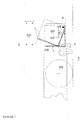
- a safety device apt to be installed in a hoisting installation of the type comprising a doorless car slidably movable in a lift shaft is generally denoted by 1.
- the safety device 1 comprises a frame 2 apt to be connected in a cantilevered manner externally and peripherally to an access opening 31 of a car 3.
- the safety device 1 comprises first elastic contrast means 4, preferably interposed between said frame 2 and said car 3 so as to keep said frame 2 substantially adhering to a wall 5 of the lift shaft.
- said elastic contrast means is springs 4.
- the frame 2 comprises a first jamb 21 and a second jamb 22 connected to the car 3. Said first jamb 21 and second jamb 22 of the frame 2 have sliding means 221 apt to slide onto the wall 5 of the lift shaft.
- the jambs 21 and 22 are articulated and comprise each at least one first 210 and one second member 211.
- said first member 210 and second member 211 are connected therebetween by a cross member 212 articulated thereto.
- the sliding means 221 is connected to said first member 210 and second member 211 so as to form "sliding block".
- the jambs 21 and 22 described hereto may comprise a plurality of members articulated thereamong, apt to perform, as in the described case, relative motions thereamong so as to allow the frame 2 to "comply” with any irregularity of the wall 5 of the lift shaft.
- the sliding means 221 is wheels 221 partially projecting from said first member 210 and said second member 211 in which they are inserted, so as to define a predetermined gap between the members 210 and 211 and the wall 5 of the lift shaft.
- Said predetermined gap preferably ranges from about 4 to 6 mm, so as to actually eliminate all hazards, such as shearing, crushing and strangling.
- said sliding means 221, in the specific case wheels 221, are kept adhering to the wall 5 by the elastic contrast means 4 acting on said first member 210 and said second member 211.
- first jamb 21 and the second jamb 22 are preferably connected to the car 3 by means of an articulated connecting rod 213 connected to the cross member 212.
- the frame 2 comprises at least one top beam 214 and/or a bottom beam 215 connected to a top end and a bottom end of said first 21 and second 22 jamb, respectively.
- said top beam 214 and said bottom beam 215 are respectively hinged to a top and bottom end of said first 21 and second 22 jamb.
- top beam 214 and the bottom beam 215 are hinged to said first jamb 21 and to said second jamb 22 so as to be apt to pivot about a longitudinal axis A thereof in the presence of items interposed between the beam 214 and/or 215 and the wall 5 of the lift shaft.
- Top 214 and bottom 215 beams are kept in a resting position by second elastic contrast means 216 connected and integral to said first 21 and said second 22 jambs, preferably by a tongue 217, as shown in detail in Figure 3.
- said second elastic contrast means 216 is preferably springs 216.
- the top beam 214 and the bottom beam 215 comprise an angular L-like member having a horizontal side 218 apt to carry out a platband function for top and bottom closure respectively of said top beam 214 and said bottom beam 215.
- the safety device 1 in a preferred embodiment, comprises a member 219 for denying and/or stopping the motion of the car, apt to be automatically actuated by said frame 2 in the presence of items interposed between the frame itself and the wall of the lift shaft.
- the safety device 1 is an automatic safety device requiring, in case of danger, no intervention by the user or a person outside, yet automatically intervening to stop the motion of the installation.
- the member 219 for denying or stopping motion is constrained to the car 3 near the connection of said top 214 and/or bottom 215 beam and said first 21 and second 22 jamb, so as to be directly actuated by said top beam and/or by said bottom beam.
- it can be actuated by the pivoting, and/or the translation in the direction of the denying and/or stopping member 219, of the top and/or bottom beam.
- said denying and/or stopping member 219 is a cutout 219.
- the safety device 1 once mounted externally and peripherally to the access opening 31 of a car 3, is adjusted and calibrated so that the sliding means 221 be substantially adhering to the wall 5 and the first 4 and second 216 elastic contrast means allow operation of the denying and/or stopping members 219 after the frame 2 has been subjected to stresses of predetermined intensity. Such a step is just carried out by acting in particular on the first 4 and second 216 elastic contrast means.
- the frame 2 connected to the car 3 and into contact with the wall 5, follows the pattern of the lift shaft by modifying its shape thanks to the articulated jambs 21 and 22 and to the first elastic contrast means 4.
- the relative motion of the various members 210, 211 and 212 assumes values higher than those previously calibrated, owing to an anomalous and therefore potentially dangerous stress (e.g. due to involuntary or forced insertion of items of extremely reduced dimensions, such as scarves, inside of the limited available gaps (about 4-6 mm) the system intervenes immediately by causing the intervention of one or more denying and/or stopping members 219, thereby locking the hoisting installation.
- Said pivoting once having exceeded a certain angle of free pivoting suitably calibrated at assembly, allows the horizontal side 218 of the beam structure to trip a cutout 219 (denying and/or stopping means), which therefore interrupts the electric circuit causing the stopping of the installation.
- the stopping of the installation at a position differing from the alignment with floor doors will activate a suitable alarm signalling system, such as a siren, or a phone dial capable of contacting the persons in charge of surveillance and/or safety.
- a suitable alarm signalling system such as a siren, or a phone dial capable of contacting the persons in charge of surveillance and/or safety.
- said safety device 1 may be connected to vertical jambs of the car entrance returns or, in the absence of the latter, along the side walls, but also onto the wall at the top and/or bottom of the access opening 31.
- each of said openings could be equipped with the safety device 1 subject-matter of the present invention.
- the present invention is susceptible of several embodiments alternative to the one described hereto; e.g., the frame 2 could be an elastic frame, made such by the use of materials having suitable elasticity for its manufacturing.
Landscapes
- Engineering & Computer Science (AREA)
- Mechanical Engineering (AREA)
- Automation & Control Theory (AREA)
- Structural Engineering (AREA)
- Lock And Its Accessories (AREA)
- Wing Frames And Configurations (AREA)
Applications Claiming Priority (1)
| Application Number | Priority Date | Filing Date | Title |
|---|---|---|---|
| ITRM20060280 ITRM20060280A1 (it) | 2006-05-26 | 2006-05-26 | Cornice elastica di sicurezza per vano di accesso ad un impianto per il sollevamenteo di persone senza porte di cabina |
Publications (1)
| Publication Number | Publication Date |
|---|---|
| EP1860052A1 true EP1860052A1 (de) | 2007-11-28 |
Family
ID=38474389
Family Applications (1)
| Application Number | Title | Priority Date | Filing Date |
|---|---|---|---|
| EP07108951A Withdrawn EP1860052A1 (de) | 2006-05-26 | 2007-05-25 | Elastischer Sicherheitsrahmen für eine Zugangsöffnung einer türlosen Personenhebevorrichtung |
Country Status (2)
| Country | Link |
|---|---|
| EP (1) | EP1860052A1 (de) |
| IT (1) | ITRM20060280A1 (de) |
Citations (3)
| Publication number | Priority date | Publication date | Assignee | Title |
|---|---|---|---|---|
| DE930111C (de) * | 1951-04-20 | 1955-07-11 | Asea Ab | Sicherheitsanordnung fuer Paternosteraufzuege |
| GB846782A (en) * | 1957-12-12 | 1960-08-31 | J & E Hall Ltd | Improvements relating to lifts |
| FR2865495A1 (fr) * | 2004-01-23 | 2005-07-29 | France Elevateurs | Ensemble comprenant une huisserie et une porte pouvant s'ouvrir a droite ou a gauche |
-
2006
- 2006-05-26 IT ITRM20060280 patent/ITRM20060280A1/it unknown
-
2007
- 2007-05-25 EP EP07108951A patent/EP1860052A1/de not_active Withdrawn
Patent Citations (3)
| Publication number | Priority date | Publication date | Assignee | Title |
|---|---|---|---|---|
| DE930111C (de) * | 1951-04-20 | 1955-07-11 | Asea Ab | Sicherheitsanordnung fuer Paternosteraufzuege |
| GB846782A (en) * | 1957-12-12 | 1960-08-31 | J & E Hall Ltd | Improvements relating to lifts |
| FR2865495A1 (fr) * | 2004-01-23 | 2005-07-29 | France Elevateurs | Ensemble comprenant une huisserie et une porte pouvant s'ouvrir a droite ou a gauche |
Also Published As
| Publication number | Publication date |
|---|---|
| ITRM20060280A1 (it) | 2007-11-30 |
Similar Documents
| Publication | Publication Date | Title |
|---|---|---|
| US5979607A (en) | Multiple level building with an elevator system operable as a means of emergency egress and evacuation during a fire incident | |
| KR102657833B1 (ko) | 엘리베이터 승강기 통로 액세스 안전 | |
| US10947087B2 (en) | Elevator safety system and method of operating an elevator system | |
| EP3257803B1 (de) | Aufzugskabine und aufzugssystem | |
| DE10108772A1 (de) | Aufzugssicherheitseinrichtung | |
| AU3244201A (en) | Shaft safety system for an elevator | |
| EP3210926B1 (de) | Aufzugswartungskonsole | |
| US20120205197A1 (en) | Elevator life safety gate | |
| EP3587324A1 (de) | Aufzugsystem | |
| KR101257717B1 (ko) | 안전 엘리베이터 시스템 | |
| AU708452B2 (en) | Lift cage movement arresting mechanism | |
| EP3366628B1 (de) | Sicherheitssystem für ein betriebsraum in einem aufzugsschacht | |
| KR100975758B1 (ko) | 엘리베이터 구조운전 회로 | |
| US5014825A (en) | Rescue operating apparatus for elevator | |
| DE19649552C2 (de) | Evakuierungssystem für Aufzüge | |
| US4357998A (en) | Between landing car door safety lock | |
| JPH034473B2 (de) | ||
| CN119117834A (zh) | 包括用于人员检测的传感器组合件的电梯系统 | |
| JP6081559B1 (ja) | エレベータのピット点検運転用安全装置 | |
| ITRM20060280A1 (it) | Cornice elastica di sicurezza per vano di accesso ad un impianto per il sollevamenteo di persone senza porte di cabina | |
| AU2017245728B2 (en) | Arrangement for evacuating persons from a lift car | |
| CN217126867U (zh) | 基于升降机的安全作业系统 | |
| CN213171058U (zh) | 一种防夹人保护装置 | |
| KR101089345B1 (ko) | 화재 발생시 구난 사다리로 변형되는 안전 난간대 | |
| DE102010004656A1 (de) | Treppen-Auf- und Abstiegssicherung für sturzgefährdete Personen |
Legal Events
| Date | Code | Title | Description |
|---|---|---|---|
| PUAI | Public reference made under article 153(3) epc to a published international application that has entered the european phase |
Free format text: ORIGINAL CODE: 0009012 |
|
| AK | Designated contracting states |
Kind code of ref document: A1 Designated state(s): AT BE BG CH CY CZ DE DK EE ES FI FR GB GR HU IE IS IT LI LT LU LV MC MT NL PL PT RO SE SI SK TR |
|
| AX | Request for extension of the european patent |
Extension state: AL BA HR MK YU |
|
| 17P | Request for examination filed |
Effective date: 20080514 |
|
| 17Q | First examination report despatched |
Effective date: 20080620 |
|
| AKX | Designation fees paid |
Designated state(s): AT BE BG CH CY CZ DE DK EE ES FI FR GB GR HU IE IS IT LI LT LU LV MC MT NL PL PT RO SE SI SK TR |
|
| STAA | Information on the status of an ep patent application or granted ep patent |
Free format text: STATUS: THE APPLICATION IS DEEMED TO BE WITHDRAWN |
|
| 18D | Application deemed to be withdrawn |
Effective date: 20081231 |