EP1860082A1 - Structure alvéolaire - Google Patents
Structure alvéolaire Download PDFInfo
- Publication number
- EP1860082A1 EP1860082A1 EP06715367A EP06715367A EP1860082A1 EP 1860082 A1 EP1860082 A1 EP 1860082A1 EP 06715367 A EP06715367 A EP 06715367A EP 06715367 A EP06715367 A EP 06715367A EP 1860082 A1 EP1860082 A1 EP 1860082A1
- Authority
- EP
- European Patent Office
- Prior art keywords
- bonding material
- material layer
- honeycomb
- honeycomb structure
- porosity
- Prior art date
- Legal status (The legal status is an assumption and is not a legal conclusion. Google has not performed a legal analysis and makes no representation as to the accuracy of the status listed.)
- Granted
Links
Images

Classifications
-
- B—PERFORMING OPERATIONS; TRANSPORTING
- B01—PHYSICAL OR CHEMICAL PROCESSES OR APPARATUS IN GENERAL
- B01D—SEPARATION
- B01D39/00—Filtering material for liquid or gaseous fluids
- B01D39/14—Other self-supporting filtering material ; Other filtering material
- B01D39/20—Other self-supporting filtering material ; Other filtering material of inorganic material, e.g. asbestos paper, metallic filtering material of non-woven wires
-
- C—CHEMISTRY; METALLURGY
- C04—CEMENTS; CONCRETE; ARTIFICIAL STONE; CERAMICS; REFRACTORIES
- C04B—LIME, MAGNESIA; SLAG; CEMENTS; COMPOSITIONS THEREOF, e.g. MORTARS, CONCRETE OR LIKE BUILDING MATERIALS; ARTIFICIAL STONE; CERAMICS; REFRACTORIES; TREATMENT OF NATURAL STONE
- C04B35/00—Shaped ceramic products characterised by their composition; Ceramics compositions; Processing powders of inorganic compounds preparatory to the manufacturing of ceramic products
- C04B35/622—Forming processes; Processing powders of inorganic compounds preparatory to the manufacturing of ceramic products
- C04B35/626—Preparing or treating the powders individually or as batches ; preparing or treating macroscopic reinforcing agents for ceramic products, e.g. fibres; mechanical aspects section B
- C04B35/63—Preparing or treating the powders individually or as batches ; preparing or treating macroscopic reinforcing agents for ceramic products, e.g. fibres; mechanical aspects section B using additives specially adapted for forming the products, e.g.. binder binders
- C04B35/6303—Inorganic additives
- C04B35/6316—Binders based on silicon compounds
-
- B—PERFORMING OPERATIONS; TRANSPORTING
- B01—PHYSICAL OR CHEMICAL PROCESSES OR APPARATUS IN GENERAL
- B01D—SEPARATION
- B01D39/00—Filtering material for liquid or gaseous fluids
- B01D39/02—Loose filtering material, e.g. loose fibres
- B01D39/06—Inorganic material, e.g. asbestos fibres, glass beads or fibres
-
- B—PERFORMING OPERATIONS; TRANSPORTING
- B01—PHYSICAL OR CHEMICAL PROCESSES OR APPARATUS IN GENERAL
- B01D—SEPARATION
- B01D46/00—Filters or filtering processes specially modified for separating dispersed particles from gases or vapours
- B01D46/24—Particle separators, e.g. dust precipitators, using rigid hollow filter bodies
- B01D46/2403—Particle separators, e.g. dust precipitators, using rigid hollow filter bodies characterised by the physical shape or structure of the filtering element
- B01D46/2418—Honeycomb filters
- B01D46/2425—Honeycomb filters characterized by parameters related to the physical properties of the honeycomb structure material
- B01D46/2448—Honeycomb filters characterized by parameters related to the physical properties of the honeycomb structure material of the adhesive layers, i.e. joints between segments
-
- B—PERFORMING OPERATIONS; TRANSPORTING
- B01—PHYSICAL OR CHEMICAL PROCESSES OR APPARATUS IN GENERAL
- B01D—SEPARATION
- B01D46/00—Filters or filtering processes specially modified for separating dispersed particles from gases or vapours
- B01D46/24—Particle separators, e.g. dust precipitators, using rigid hollow filter bodies
- B01D46/2403—Particle separators, e.g. dust precipitators, using rigid hollow filter bodies characterised by the physical shape or structure of the filtering element
- B01D46/2418—Honeycomb filters
- B01D46/2425—Honeycomb filters characterized by parameters related to the physical properties of the honeycomb structure material
- B01D46/24491—Porosity
-
- B—PERFORMING OPERATIONS; TRANSPORTING
- B01—PHYSICAL OR CHEMICAL PROCESSES OR APPARATUS IN GENERAL
- B01D—SEPARATION
- B01D46/00—Filters or filtering processes specially modified for separating dispersed particles from gases or vapours
- B01D46/24—Particle separators, e.g. dust precipitators, using rigid hollow filter bodies
- B01D46/2403—Particle separators, e.g. dust precipitators, using rigid hollow filter bodies characterised by the physical shape or structure of the filtering element
- B01D46/2418—Honeycomb filters
- B01D46/2425—Honeycomb filters characterized by parameters related to the physical properties of the honeycomb structure material
- B01D46/24495—Young's modulus
-
- B—PERFORMING OPERATIONS; TRANSPORTING
- B01—PHYSICAL OR CHEMICAL PROCESSES OR APPARATUS IN GENERAL
- B01D—SEPARATION
- B01D46/00—Filters or filtering processes specially modified for separating dispersed particles from gases or vapours
- B01D46/24—Particle separators, e.g. dust precipitators, using rigid hollow filter bodies
- B01D46/2403—Particle separators, e.g. dust precipitators, using rigid hollow filter bodies characterised by the physical shape or structure of the filtering element
- B01D46/2418—Honeycomb filters
- B01D46/2451—Honeycomb filters characterized by the geometrical structure, shape, pattern or configuration or parameters related to the geometry of the structure
- B01D46/2466—Honeycomb filters characterized by the geometrical structure, shape, pattern or configuration or parameters related to the geometry of the structure of the adhesive layers, i.e. joints between segments
-
- B—PERFORMING OPERATIONS; TRANSPORTING
- B01—PHYSICAL OR CHEMICAL PROCESSES OR APPARATUS IN GENERAL
- B01D—SEPARATION
- B01D46/00—Filters or filtering processes specially modified for separating dispersed particles from gases or vapours
- B01D46/24—Particle separators, e.g. dust precipitators, using rigid hollow filter bodies
- B01D46/2403—Particle separators, e.g. dust precipitators, using rigid hollow filter bodies characterised by the physical shape or structure of the filtering element
- B01D46/2418—Honeycomb filters
- B01D46/2451—Honeycomb filters characterized by the geometrical structure, shape, pattern or configuration or parameters related to the geometry of the structure
- B01D46/2478—Structures comprising honeycomb segments
-
- B—PERFORMING OPERATIONS; TRANSPORTING
- B01—PHYSICAL OR CHEMICAL PROCESSES OR APPARATUS IN GENERAL
- B01D—SEPARATION
- B01D46/00—Filters or filtering processes specially modified for separating dispersed particles from gases or vapours
- B01D46/24—Particle separators, e.g. dust precipitators, using rigid hollow filter bodies
- B01D46/2403—Particle separators, e.g. dust precipitators, using rigid hollow filter bodies characterised by the physical shape or structure of the filtering element
- B01D46/2418—Honeycomb filters
- B01D46/2451—Honeycomb filters characterized by the geometrical structure, shape, pattern or configuration or parameters related to the geometry of the structure
- B01D46/2482—Thickness, height, width, length or diameter
-
- B—PERFORMING OPERATIONS; TRANSPORTING
- B01—PHYSICAL OR CHEMICAL PROCESSES OR APPARATUS IN GENERAL
- B01D—SEPARATION
- B01D46/00—Filters or filtering processes specially modified for separating dispersed particles from gases or vapours
- B01D46/24—Particle separators, e.g. dust precipitators, using rigid hollow filter bodies
- B01D46/2403—Particle separators, e.g. dust precipitators, using rigid hollow filter bodies characterised by the physical shape or structure of the filtering element
- B01D46/2418—Honeycomb filters
- B01D46/2498—The honeycomb filter being defined by mathematical relationships
-
- C—CHEMISTRY; METALLURGY
- C04—CEMENTS; CONCRETE; ARTIFICIAL STONE; CERAMICS; REFRACTORIES
- C04B—LIME, MAGNESIA; SLAG; CEMENTS; COMPOSITIONS THEREOF, e.g. MORTARS, CONCRETE OR LIKE BUILDING MATERIALS; ARTIFICIAL STONE; CERAMICS; REFRACTORIES; TREATMENT OF NATURAL STONE
- C04B37/00—Joining burned ceramic articles with other burned ceramic articles or other articles by heating
-
- C—CHEMISTRY; METALLURGY
- C04—CEMENTS; CONCRETE; ARTIFICIAL STONE; CERAMICS; REFRACTORIES
- C04B—LIME, MAGNESIA; SLAG; CEMENTS; COMPOSITIONS THEREOF, e.g. MORTARS, CONCRETE OR LIKE BUILDING MATERIALS; ARTIFICIAL STONE; CERAMICS; REFRACTORIES; TREATMENT OF NATURAL STONE
- C04B38/00—Porous mortars, concrete, artificial stone or ceramic ware; Preparation thereof
- C04B38/0006—Honeycomb structures
- C04B38/0009—Honeycomb structures characterised by features relating to the cell walls, e.g. wall thickness or distribution of pores in the walls
-
- C—CHEMISTRY; METALLURGY
- C04—CEMENTS; CONCRETE; ARTIFICIAL STONE; CERAMICS; REFRACTORIES
- C04B—LIME, MAGNESIA; SLAG; CEMENTS; COMPOSITIONS THEREOF, e.g. MORTARS, CONCRETE OR LIKE BUILDING MATERIALS; ARTIFICIAL STONE; CERAMICS; REFRACTORIES; TREATMENT OF NATURAL STONE
- C04B38/00—Porous mortars, concrete, artificial stone or ceramic ware; Preparation thereof
- C04B38/0006—Honeycomb structures
- C04B38/0016—Honeycomb structures assembled from subunits
- C04B38/0019—Honeycomb structures assembled from subunits characterised by the material used for joining separate subunits
-
- C—CHEMISTRY; METALLURGY
- C04—CEMENTS; CONCRETE; ARTIFICIAL STONE; CERAMICS; REFRACTORIES
- C04B—LIME, MAGNESIA; SLAG; CEMENTS; COMPOSITIONS THEREOF, e.g. MORTARS, CONCRETE OR LIKE BUILDING MATERIALS; ARTIFICIAL STONE; CERAMICS; REFRACTORIES; TREATMENT OF NATURAL STONE
- C04B38/00—Porous mortars, concrete, artificial stone or ceramic ware; Preparation thereof
- C04B38/008—Bodies obtained by assembling separate elements having such a configuration that the final product is porous or by spirally winding one or more corrugated sheets
-
- F—MECHANICAL ENGINEERING; LIGHTING; HEATING; WEAPONS; BLASTING
- F01—MACHINES OR ENGINES IN GENERAL; ENGINE PLANTS IN GENERAL; STEAM ENGINES
- F01N—GAS-FLOW SILENCERS OR EXHAUST APPARATUS FOR MACHINES OR ENGINES IN GENERAL; GAS-FLOW SILENCERS OR EXHAUST APPARATUS FOR INTERNAL-COMBUSTION ENGINES
- F01N3/00—Exhaust or silencing apparatus having means for purifying, rendering innocuous, or otherwise treating exhaust
- F01N3/02—Exhaust or silencing apparatus having means for purifying, rendering innocuous, or otherwise treating exhaust for cooling, or for removing solid constituents of, exhaust
-
- F—MECHANICAL ENGINEERING; LIGHTING; HEATING; WEAPONS; BLASTING
- F01—MACHINES OR ENGINES IN GENERAL; ENGINE PLANTS IN GENERAL; STEAM ENGINES
- F01N—GAS-FLOW SILENCERS OR EXHAUST APPARATUS FOR MACHINES OR ENGINES IN GENERAL; GAS-FLOW SILENCERS OR EXHAUST APPARATUS FOR INTERNAL-COMBUSTION ENGINES
- F01N3/00—Exhaust or silencing apparatus having means for purifying, rendering innocuous, or otherwise treating exhaust
- F01N3/02—Exhaust or silencing apparatus having means for purifying, rendering innocuous, or otherwise treating exhaust for cooling, or for removing solid constituents of, exhaust
- F01N3/021—Exhaust or silencing apparatus having means for purifying, rendering innocuous, or otherwise treating exhaust for cooling, or for removing solid constituents of, exhaust by means of filters
- F01N3/022—Exhaust or silencing apparatus having means for purifying, rendering innocuous, or otherwise treating exhaust for cooling, or for removing solid constituents of, exhaust by means of filters characterised by specially adapted filtering structure, e.g. honeycomb, mesh or fibrous
- F01N3/0222—Exhaust or silencing apparatus having means for purifying, rendering innocuous, or otherwise treating exhaust for cooling, or for removing solid constituents of, exhaust by means of filters characterised by specially adapted filtering structure, e.g. honeycomb, mesh or fibrous the structure being monolithic, e.g. honeycombs
-
- B—PERFORMING OPERATIONS; TRANSPORTING
- B01—PHYSICAL OR CHEMICAL PROCESSES OR APPARATUS IN GENERAL
- B01D—SEPARATION
- B01D2279/00—Filters adapted for separating dispersed particles from gases or vapours specially modified for specific uses
- B01D2279/30—Filters adapted for separating dispersed particles from gases or vapours specially modified for specific uses for treatment of exhaust gases from IC Engines
-
- C—CHEMISTRY; METALLURGY
- C04—CEMENTS; CONCRETE; ARTIFICIAL STONE; CERAMICS; REFRACTORIES
- C04B—LIME, MAGNESIA; SLAG; CEMENTS; COMPOSITIONS THEREOF, e.g. MORTARS, CONCRETE OR LIKE BUILDING MATERIALS; ARTIFICIAL STONE; CERAMICS; REFRACTORIES; TREATMENT OF NATURAL STONE
- C04B2111/00—Mortars, concrete or artificial stone or mixtures to prepare them, characterised by specific function, property or use
- C04B2111/00474—Uses not provided for elsewhere in C04B2111/00
- C04B2111/00793—Uses not provided for elsewhere in C04B2111/00 as filters or diaphragms
-
- C—CHEMISTRY; METALLURGY
- C04—CEMENTS; CONCRETE; ARTIFICIAL STONE; CERAMICS; REFRACTORIES
- C04B—LIME, MAGNESIA; SLAG; CEMENTS; COMPOSITIONS THEREOF, e.g. MORTARS, CONCRETE OR LIKE BUILDING MATERIALS; ARTIFICIAL STONE; CERAMICS; REFRACTORIES; TREATMENT OF NATURAL STONE
- C04B2111/00—Mortars, concrete or artificial stone or mixtures to prepare them, characterised by specific function, property or use
- C04B2111/00474—Uses not provided for elsewhere in C04B2111/00
- C04B2111/0081—Uses not provided for elsewhere in C04B2111/00 as catalysts or catalyst carriers
-
- C—CHEMISTRY; METALLURGY
- C04—CEMENTS; CONCRETE; ARTIFICIAL STONE; CERAMICS; REFRACTORIES
- C04B—LIME, MAGNESIA; SLAG; CEMENTS; COMPOSITIONS THEREOF, e.g. MORTARS, CONCRETE OR LIKE BUILDING MATERIALS; ARTIFICIAL STONE; CERAMICS; REFRACTORIES; TREATMENT OF NATURAL STONE
- C04B2111/00—Mortars, concrete or artificial stone or mixtures to prepare them, characterised by specific function, property or use
- C04B2111/20—Resistance against chemical, physical or biological attack
- C04B2111/2084—Thermal shock resistance
-
- C—CHEMISTRY; METALLURGY
- C04—CEMENTS; CONCRETE; ARTIFICIAL STONE; CERAMICS; REFRACTORIES
- C04B—LIME, MAGNESIA; SLAG; CEMENTS; COMPOSITIONS THEREOF, e.g. MORTARS, CONCRETE OR LIKE BUILDING MATERIALS; ARTIFICIAL STONE; CERAMICS; REFRACTORIES; TREATMENT OF NATURAL STONE
- C04B2235/00—Aspects relating to ceramic starting mixtures or sintered ceramic products
- C04B2235/02—Composition of constituents of the starting material or of secondary phases of the final product
- C04B2235/30—Constituents and secondary phases not being of a fibrous nature
- C04B2235/34—Non-metal oxides, non-metal mixed oxides, or salts thereof that form the non-metal oxides upon heating, e.g. carbonates, nitrates, (oxy)hydroxides, chlorides
- C04B2235/3418—Silicon oxide, silicic acids or oxide forming salts thereof, e.g. silica sol, fused silica, silica fume, cristobalite, quartz or flint
-
- C—CHEMISTRY; METALLURGY
- C04—CEMENTS; CONCRETE; ARTIFICIAL STONE; CERAMICS; REFRACTORIES
- C04B—LIME, MAGNESIA; SLAG; CEMENTS; COMPOSITIONS THEREOF, e.g. MORTARS, CONCRETE OR LIKE BUILDING MATERIALS; ARTIFICIAL STONE; CERAMICS; REFRACTORIES; TREATMENT OF NATURAL STONE
- C04B2235/00—Aspects relating to ceramic starting mixtures or sintered ceramic products
- C04B2235/02—Composition of constituents of the starting material or of secondary phases of the final product
- C04B2235/30—Constituents and secondary phases not being of a fibrous nature
- C04B2235/34—Non-metal oxides, non-metal mixed oxides, or salts thereof that form the non-metal oxides upon heating, e.g. carbonates, nitrates, (oxy)hydroxides, chlorides
- C04B2235/3427—Silicates other than clay, e.g. water glass
-
- C—CHEMISTRY; METALLURGY
- C04—CEMENTS; CONCRETE; ARTIFICIAL STONE; CERAMICS; REFRACTORIES
- C04B—LIME, MAGNESIA; SLAG; CEMENTS; COMPOSITIONS THEREOF, e.g. MORTARS, CONCRETE OR LIKE BUILDING MATERIALS; ARTIFICIAL STONE; CERAMICS; REFRACTORIES; TREATMENT OF NATURAL STONE
- C04B2235/00—Aspects relating to ceramic starting mixtures or sintered ceramic products
- C04B2235/02—Composition of constituents of the starting material or of secondary phases of the final product
- C04B2235/30—Constituents and secondary phases not being of a fibrous nature
- C04B2235/34—Non-metal oxides, non-metal mixed oxides, or salts thereof that form the non-metal oxides upon heating, e.g. carbonates, nitrates, (oxy)hydroxides, chlorides
- C04B2235/349—Clays, e.g. bentonites, smectites such as montmorillonite, vermiculites or kaolines, e.g. illite, talc or sepiolite
-
- C—CHEMISTRY; METALLURGY
- C04—CEMENTS; CONCRETE; ARTIFICIAL STONE; CERAMICS; REFRACTORIES
- C04B—LIME, MAGNESIA; SLAG; CEMENTS; COMPOSITIONS THEREOF, e.g. MORTARS, CONCRETE OR LIKE BUILDING MATERIALS; ARTIFICIAL STONE; CERAMICS; REFRACTORIES; TREATMENT OF NATURAL STONE
- C04B2235/00—Aspects relating to ceramic starting mixtures or sintered ceramic products
- C04B2235/02—Composition of constituents of the starting material or of secondary phases of the final product
- C04B2235/30—Constituents and secondary phases not being of a fibrous nature
- C04B2235/38—Non-oxide ceramic constituents or additives
- C04B2235/3817—Carbides
- C04B2235/3826—Silicon carbides
-
- C—CHEMISTRY; METALLURGY
- C04—CEMENTS; CONCRETE; ARTIFICIAL STONE; CERAMICS; REFRACTORIES
- C04B—LIME, MAGNESIA; SLAG; CEMENTS; COMPOSITIONS THEREOF, e.g. MORTARS, CONCRETE OR LIKE BUILDING MATERIALS; ARTIFICIAL STONE; CERAMICS; REFRACTORIES; TREATMENT OF NATURAL STONE
- C04B2235/00—Aspects relating to ceramic starting mixtures or sintered ceramic products
- C04B2235/02—Composition of constituents of the starting material or of secondary phases of the final product
- C04B2235/50—Constituents or additives of the starting mixture chosen for their shape or used because of their shape or their physical appearance
- C04B2235/52—Constituents or additives characterised by their shapes
- C04B2235/5208—Fibers
- C04B2235/5216—Inorganic
- C04B2235/522—Oxidic
- C04B2235/5228—Silica and alumina, including aluminosilicates, e.g. mullite
-
- C—CHEMISTRY; METALLURGY
- C04—CEMENTS; CONCRETE; ARTIFICIAL STONE; CERAMICS; REFRACTORIES
- C04B—LIME, MAGNESIA; SLAG; CEMENTS; COMPOSITIONS THEREOF, e.g. MORTARS, CONCRETE OR LIKE BUILDING MATERIALS; ARTIFICIAL STONE; CERAMICS; REFRACTORIES; TREATMENT OF NATURAL STONE
- C04B2235/00—Aspects relating to ceramic starting mixtures or sintered ceramic products
- C04B2235/02—Composition of constituents of the starting material or of secondary phases of the final product
- C04B2235/50—Constituents or additives of the starting mixture chosen for their shape or used because of their shape or their physical appearance
- C04B2235/52—Constituents or additives characterised by their shapes
- C04B2235/5208—Fibers
- C04B2235/526—Fibers characterised by the length of the fibers
-
- C—CHEMISTRY; METALLURGY
- C04—CEMENTS; CONCRETE; ARTIFICIAL STONE; CERAMICS; REFRACTORIES
- C04B—LIME, MAGNESIA; SLAG; CEMENTS; COMPOSITIONS THEREOF, e.g. MORTARS, CONCRETE OR LIKE BUILDING MATERIALS; ARTIFICIAL STONE; CERAMICS; REFRACTORIES; TREATMENT OF NATURAL STONE
- C04B2235/00—Aspects relating to ceramic starting mixtures or sintered ceramic products
- C04B2235/02—Composition of constituents of the starting material or of secondary phases of the final product
- C04B2235/50—Constituents or additives of the starting mixture chosen for their shape or used because of their shape or their physical appearance
- C04B2235/52—Constituents or additives characterised by their shapes
- C04B2235/5208—Fibers
- C04B2235/5264—Fibers characterised by the diameter of the fibers
-
- C—CHEMISTRY; METALLURGY
- C04—CEMENTS; CONCRETE; ARTIFICIAL STONE; CERAMICS; REFRACTORIES
- C04B—LIME, MAGNESIA; SLAG; CEMENTS; COMPOSITIONS THEREOF, e.g. MORTARS, CONCRETE OR LIKE BUILDING MATERIALS; ARTIFICIAL STONE; CERAMICS; REFRACTORIES; TREATMENT OF NATURAL STONE
- C04B2235/00—Aspects relating to ceramic starting mixtures or sintered ceramic products
- C04B2235/70—Aspects relating to sintered or melt-casted ceramic products
- C04B2235/74—Physical characteristics
- C04B2235/77—Density
-
- C—CHEMISTRY; METALLURGY
- C04—CEMENTS; CONCRETE; ARTIFICIAL STONE; CERAMICS; REFRACTORIES
- C04B—LIME, MAGNESIA; SLAG; CEMENTS; COMPOSITIONS THEREOF, e.g. MORTARS, CONCRETE OR LIKE BUILDING MATERIALS; ARTIFICIAL STONE; CERAMICS; REFRACTORIES; TREATMENT OF NATURAL STONE
- C04B2235/00—Aspects relating to ceramic starting mixtures or sintered ceramic products
- C04B2235/70—Aspects relating to sintered or melt-casted ceramic products
- C04B2235/96—Properties of ceramic products, e.g. mechanical properties such as strength, toughness, wear resistance
-
- C—CHEMISTRY; METALLURGY
- C04—CEMENTS; CONCRETE; ARTIFICIAL STONE; CERAMICS; REFRACTORIES
- C04B—LIME, MAGNESIA; SLAG; CEMENTS; COMPOSITIONS THEREOF, e.g. MORTARS, CONCRETE OR LIKE BUILDING MATERIALS; ARTIFICIAL STONE; CERAMICS; REFRACTORIES; TREATMENT OF NATURAL STONE
- C04B2235/00—Aspects relating to ceramic starting mixtures or sintered ceramic products
- C04B2235/70—Aspects relating to sintered or melt-casted ceramic products
- C04B2235/96—Properties of ceramic products, e.g. mechanical properties such as strength, toughness, wear resistance
- C04B2235/9607—Thermal properties, e.g. thermal expansion coefficient
-
- Y—GENERAL TAGGING OF NEW TECHNOLOGICAL DEVELOPMENTS; GENERAL TAGGING OF CROSS-SECTIONAL TECHNOLOGIES SPANNING OVER SEVERAL SECTIONS OF THE IPC; TECHNICAL SUBJECTS COVERED BY FORMER USPC CROSS-REFERENCE ART COLLECTIONS [XRACs] AND DIGESTS
- Y02—TECHNOLOGIES OR APPLICATIONS FOR MITIGATION OR ADAPTATION AGAINST CLIMATE CHANGE
- Y02T—CLIMATE CHANGE MITIGATION TECHNOLOGIES RELATED TO TRANSPORTATION
- Y02T10/00—Road transport of goods or passengers
- Y02T10/10—Internal combustion engine [ICE] based vehicles
- Y02T10/12—Improving ICE efficiencies
-
- Y—GENERAL TAGGING OF NEW TECHNOLOGICAL DEVELOPMENTS; GENERAL TAGGING OF CROSS-SECTIONAL TECHNOLOGIES SPANNING OVER SEVERAL SECTIONS OF THE IPC; TECHNICAL SUBJECTS COVERED BY FORMER USPC CROSS-REFERENCE ART COLLECTIONS [XRACs] AND DIGESTS
- Y10—TECHNICAL SUBJECTS COVERED BY FORMER USPC
- Y10T—TECHNICAL SUBJECTS COVERED BY FORMER US CLASSIFICATION
- Y10T428/00—Stock material or miscellaneous articles
- Y10T428/24—Structurally defined web or sheet [e.g., overall dimension, etc.]
- Y10T428/24149—Honeycomb-like
Definitions
- the present invention relates to a honeycomb structure where a plurality of honeycomb segments are integrally joined with one another by means of a bonding material layer. More particularly, the present invention relates to a honeycomb structure which is useful as a trapping filter for exhaust gas, particularly as a diesel particulate filter for trapping particulate matter or the like in exhaust gas from a diesel engine, which is excellent in thermal shock resistance, and where a defect such as a crack is securely inhibited from generating particularly upon regenerating the filter.
- a honeycomb structure is incorporated into an exhaust gas system or the like of a diesel engine as a trapping filter for exhaust gas, for example, a diesel particulate filter (DPF) for trapping and removing particulate matter contained in exhaust gas from a diesel engine or the like.
- a trapping filter for exhaust gas for example, a diesel particulate filter (DPF) for trapping and removing particulate matter contained in exhaust gas from a diesel engine or the like.
- DPF diesel particulate filter
- Such a honeycomb structure has a structure in which a plurality of cells partitioned by porous partition walls made of, for example, silicon carbide (SiC) and functioning as fluid passages are disposed in parallel with one another in the direction of the central axis. End portions of adjacent cells are alternately plugged (in a checkerwise pattern). That is, a cell has an open end on one side and a closed end on the other side, and other cells adjacent to the cell have a closed end on one side and an open end on the other side.
- SiC silicon carbide
- exhaust gas can be purified by allowing the gas flowing into predetermined cells (inflow cells) from an end portion to pass through porous partition walls and flow out via the cells (outflow cells) adjacent to the inflow cells, thereby allowing the partition walls to trap particulate matter in exhaust gas when the exhaust gas passes through the partition walls.
- a honeycomb structure having a block structure having a function of dispersing and releasing the thermal stress by integrally joining a plurality of honeycomb segments by means of a bonding material layer, and the thermal shock resistance has been improved to some extent.
- Such a honeycomb structure having a block structure has a structure in which a plurality of segments each having a shape constituting a part of the whole structure and having a shape constituting the whole structure by joining with one another in the direction perpendicular to the central axis are integrally joined by means of a bonding material layer so that a cross-section of the whole structure taken along a plane perpendicular to the central axis has a predetermined shape such as a circle, followed by coating the outer peripheral surface with a coating material.
- a bonding material layer for integrally joining a plurality of honeycomb segments is desired to achieve a honeycomb structure having an excellent thermal shock resistance by achieving an excellent stress-releasing function and bonding strength.
- Patent Document 1 Japanese Patent No. 3121497
- the present invention has been made in view of the above problem and aims to provide a honeycomb structure which is useful as a trapping filter for exhaust gas, particularly as a diesel particulate filter for trapping particulate matter or the like in exhaust gas from a diesel engine, which is excellent in thermal shock resistance, and where a defect such as a crack is securely inhibited from generating particularly upon regenerating the filter.
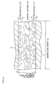
- a honeycomb structure comprising a honeycomb segment joined body having a plurality of honeycomb segments integrally joined with one another at a joint face of each of the honeycomb segments by means of a bonding material layer and having a plurality of cells functioning as fluid passages disposed in parallel with one another in a direction of central axis, wherein porosity in an outside portion of the bonding material layer (portion from the interface of the joint face of honeycomb segments to the point corresponding to 20% thickness of the total bonding material layer) is smaller than that in the central portion located on the inner side of the outside portion.
- the bonding material layer contains an inorganic fiber with the inorganic fiber content ratio of 20 to 45% by mass and the shot content ratio of 10 to 50% by mass, and it has an average diameter of 1 to 20 ⁇ m in a cross-section perpendicular to the longer axial direction and an average length of 10 to 400 ⁇ m in the longer axial direction.
- honeycomb structure according to any one of the above [1] to [8], wherein the honeycomb segment is constituted by silicon carbide (SiC) or by silicon-silicon carbide based composite material produced by the silicon carbide (SiC) as a framework and silicon (Si) as a bonding material.
- SiC silicon carbide
- SiC silicon-silicon carbide based composite material produced by the silicon carbide (SiC) as a framework and silicon (Si) as a bonding material.
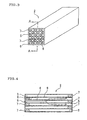
- a honeycomb structure 1 in an embodiment of the present invention is provided with a honeycomb segment joined body 10 having a plurality of honeycomb segments 2 integrally joined with one another at a joint face of each of the honeycomb segments 2 by means of a bonding material layer 9 and has a plurality of cells 5 functioning as fluid passages disposed in parallel with one another in a direction of central axis.
- the honeycomb structure is characterized in that a porosity in an outside portion of the bonding material layer 9 (portion from the interface of the joint face of honeycomb segments to the point corresponding to 20% thickness of the total bonding material layer) is smaller than that in the central portion located on the inner side of the outside portion and that the bonding material layer 9 satisfies the relation of strength (MPa) / Young's modulus (GPa) > 1.0 ⁇ 10 -3 .
- a honeycomb structure 1 in an embodiment of the present invention has a structure in which a plurality of cells 5 partitioned and formed by porous partition walls 6 and works as fluid passages are disposed in parallel with one another in the direction of the central axis of the honeycomb structure 1.
- the honeycomb structure 1 is constituted as a honeycomb segment joined body 10 in which a plurality of honeycomb segment 2 each of which has a shape for constituting a part of the whole structure and a shape for constituting the whole structure by being assembled in a direction perpendicular to the central axis of a honeycomb structure 1 are integrally joined by means of a bonding material layer 9.
- the honeycomb segments 2 are joined by means of a bonding material layer 9, the honeycomb segments 2 are subjected to grinding processing so that the cross-section of the whole structure taken along a plane perpendicular to the central axis of the honeycomb structure 1 may have a shape of a circle, an ellipse, a triangle, a square, or another shape, and the outer peripheral surface is coated with a coating material 4.
- the honeycomb structure 1 as a DPF
- by disposing the honeycomb structure 1 in an exhaust gas system, or the like, of a diesel engine particulate matter containing soot exhausted from the diesel engine can be trapped.
- cells 5 and partition walls 6 are depicted only in one honeycomb segment 2.
- Each honeycomb segment 2 has a shape for constituting a part of the whole structure of a honeycomb structure 1 (honeycomb segment joined body 10) (see Fig. 1) as shown in Figs. 3 and 4 and a shape for constituting the whole structure by being assembled in a direction perpendicular to the central axis of the honeycomb structure 1 (see Fig. 1).
- the cells 5 are disposed to be in parallel with one another in the direction of the central axis of the honeycomb structure 1, and each end portion of cells 5 adjacent thereto are alternately plugged with a filler 7.
- Predetermined cells 5 are opened on the left side end portion in Figs. 3 and 4 and plugged on the right side end portion with a filler 7.
- Other cells 5 (outflow cells) adjacent to the predetermined cells 5 are plugged on the left side end portion with the filler 7 and opened on the right side end portion.
- each of the end portions of the honeycomb segment 2 shows a checkerwise pattern as shown in Fig. 2.
- exhaust gas flows into the cells 5 of the each honeycomb segments 2 from the left side shown in Fig. 4 and moves to the right side.
- Fig. 4 shows a case that exhaust gas enters from left side of the honeycomb segment 2, and exhaust gas flows into the honeycomb segment 2 from the cells 5 (inflow cells) which are opened without being plugged.
- the exhaust gas flowing into the cells 5 (inflow cells) passes through porous partition walls 6 and flows out from the other cells 5 (outflow cells).
- particulate matter containing soot in the exhaust gas can be trapped by the partition walls 6.
- exhaust gas is purified.
- particulate matter containing soot accumulates inside the honeycomb segments 2 in the course of time to increase pressure loss. Therefore, regeneration is performed to burn soot and the like.
- the cross-section may have a shape of a triangle, a hexagon, or the like.
- a cross-section of the cells 5 may have a shape of a triangle, a hexagon, a circle, an ellipse, or the like.
- a honeycomb structure has the aforementioned structure and characterized in that a porosity in an outside portion of the bonding material layer 9 (portion from the interface of the joint face of honeycomb segments to the point corresponding to 20% thickness of the total bonding material layer) is smaller than that in the central portion located on the inner side of the outside portion and that the bonding material layer 9 satisfies the relation of strength (MPa) /Young's modulus (GPa) > 1.0 ⁇ 10 -3 [preferably, strength (MPa) / Young's modulus (GPa) > 2.5 ⁇ 10 -3 , more preferably, strength (MPa) / Young's modulus (GPa) > 3.5 ⁇ 10 -3 ].
- the outside portion of the bonding material layer used in the present embodiment has a porosity of 5 to 40% and that the central portion has a porosity of 25 to 90%. It is more preferable that the outside portion of the bonding material layer 9 has a porosity of 10 to 30% and that the central portion has a porosity of 30 to 70%.
- the porosity in the outside portion is smaller than 5%, the Young's modulus becomes large, and a stress-releasing function may not be exhibited sufficiently.
- the porosity in the outside portion is larger than 40%, bonding strength between a segment and a bonding material layer may be lowered.
- the bonding material layer portion has an average porosity of 17 to 70%, more preferably 22 to 54%.
- the bonding material layer used in the present embodiment contains inorganic fiber, and it is preferable the bonding material layer contains, for example, an inorganic binder, an organic binder, an inorganic particle, a foaming particle, and the like, besides the inorganic fiber.
- the inorganic fiber include aluminosilicate, alumina, SiO 2 -MgO based and SiO 2 -CaO-Mg based oxide fiber, and other fiber (e.g., SiC fiber).
- the inorganic binder include silica sol, alumina sol, and clay.
- the organic binder include polyvinyl alcohol (PVA), carboxymethyl cellulose (CMC), and methyl cellulose (MC).
- the inorganic particle examples include ceramics such as silicon carbide, silicon nitride, cordierite, alumina, and mullite.
- ceramics such as silicon carbide, silicon nitride, cordierite, alumina, and mullite.
- bonding material constituting the bonding material layer, the same material as the coating material described below may be used.
- the content ratio of the inorganic fiber is preferably 20 to 45% by mass (more preferably 30 to 40% by mass), the shot content ratio is preferably 10 to 50% by mass, an average diameter in a cross-section perpendicular to the direction of the longer axis is 1 to 20 ⁇ m (more preferably 2 to 15 ⁇ m), and an average length in the direction of the longer axis is 10 to 600 ⁇ m (more preferably 50 to 300 ⁇ m).
- the content ratio of the inorganic fiber When the content ratio of the inorganic fiber is below 20% by mass, it may be impossible to impart elasticity to the bonding material layer.
- the content ratio When the content ratio is above 45% by mass, a large amount of water is required to obtain applicable paste. Use of a large amount of water causes large shrinkage upon drying the bonding material, and a crack may be caused.
- the shot content ratio is below 10% by mass, a large amount of water is required to obtain applicable paste. Use of a large amount of water causes large shrinkage upon drying the bonding material, and cracks may be caused.
- the content ratio When the content ratio is above 50% by mass, it may be impossible to impart elasticity to the bonding material layer.
- the average diameter in a cross-section perpendicular to the direction of the longer axis is below 1 ⁇ m, it may be impossible to impart elasticity to the bonding material layer.
- the average diameter is above 20 ⁇ m, it has a large influence on thickness of the bonding material, and therefore, it is sometimes difficult to apply it uniformly on the outer wall surface of the honeycomb segment.
- the average length in the longer axis is below 10 ⁇ m, it may be impossible to impart elasticity to the bonding material layer.
- the average length in the longer axis is above 600 ⁇ m, the applicability may be lowered.
- a bonding material layer 9 is applied on an outer peripheral surface of each of the honeycomb segments 2 to function so that it joins the honeycomb segments 2.
- the bonding material layer 9 may be applied on the outer peripheral surface of each of the adjacent honeycomb segments 2 or only on one of the opposing outer peripheral surfaces of the adjacent honeycomb segments 2. Such application on only one of the opposing surfaces is preferable in that an amount of the bonding material layer 9 can be saved.
- the thickness of the bonding material layer 9 is determined in consideration of bonding force between honeycomb segments 2 and appropriately selected, for example, within the range between 0.5 to 3.0 mm.
- Examples of the material for the honeycomb segment 2 used in the present embodiment include a material constituted by at least one selected from the group consisting of silicon carbide, silicon-silicon carbide based compound material produced with silicon carbide (SiC) as a framework and silicon (Si) as a bonding material, silicon nitride, cordierite, mullite, alumina, spinel, silicon carbide-cordierite based composite material, silicon-silicon carbide composite material, lithium aluminum silicate, aluminum titanate, and Fe-Cr-Al based metal from the viewpoint of strength and heat resistance.
- a material constituted by a silicon carbide (SiC) or silicon-silicon carbide based composite material is preferable.
- the honeycomb segment 2 can be manufactured by, for example, adding a binder such as methyl cellulose, hydroxypropoxyl cellulose, hydroxyethyl cellulose, carboxymethyl cellulose, and polyvinyl alcohol, a surfactant, water as a solvent, and the like, to a material appropriately selected from the aforementioned materials, to obtain clay having plasticity, subjecting the clay to extrusion forming to give a formed body having the aforementioned shape, drying the formed body with microwaves, hot air, or the like, and sintering the formed body.
- a binder such as methyl cellulose, hydroxypropoxyl cellulose, hydroxyethyl cellulose, carboxymethyl cellulose, and polyvinyl alcohol, a surfactant, water as a solvent, and the like
- Plugging with the filler 7 can be performed by immersing an end face of the honeycomb segment 2 in the slurried filler 7 with the cells 5 which are not to be plugged being masked so that the filler 7 can be filled into only opening cells 5.
- the filler 7 can be filled before or after firing the honeycomb segment 2 being formed. However, filling before firing is preferable because only one firing process is required.
- a slurried bonding material 9 is applied on an outer peripheral surface of the honeycomb segment 2, a plurality of honeycomb segments 2 are assembled to give a predetermined solid shape (whole structure of the honeycomb structure 1), press-fitted in this assembled state, and dried by heating.
- a joined body having a plurality of honeycomb segments 2 integrally joined is manufactured.
- the joined body is subjected to grinding processing to give the predetermined shape.
- the outer peripheral surface is coated with the coating material 4, which is dried by heating.
- a honeycomb structure 1 shown in Fig. 1 is manufactured.
- a material for the coating material 4 a material similar to that for the bonding material layer 9 can be used.
- the thickness of the coating material 4 is appropriately selected within the range between 0.1 to 1.5 mm.
- a honeycomb structure which is useful as a trapping filter for exhaust gas, particularly as a diesel particulate filter for trapping particulate matter or the like in exhaust gas from a diesel engine, which is excellent in thermal shock resistance, and where defects such as cracks are securely inhibited from causing particularly upon regenerating the filter.
- honeycomb segment material SiC powder and metal Si powder were mixed together at the ratio of 80:20 by mass to give a mixture.
- starch and a foaming resin as pore formers were added to the mixture to prepare clay having plasticity.
- the clay was subjected to extrusion forming and dried with microwaves and hot air to obtain a honeycomb segment formed body having a partition wall thickness of 310 ⁇ m, a cell density of about 46.5 cells/cm 2 (300 cells/inch 2 ), a square cross-section with a side length of 35 mm, and a length of 152 mm.
- the honeycomb segment formed body was subjected to plugging at both end faces so that each of the end faces shows a checkerwise pattern. That is, plugging was performed so that adjacent cells are plugged at the opposite end portions.
- As the plugging material a material similar to that for the honeycomb segment raw material was used. After plugging the both end faces and drying, the binder was degreased at about 400°C in an ambient atmosphere, and then firing was performed at about 1450°C in an Ar inert atmosphere to obtain a honeycomb segment having a porous structure, in which SiC crystal particles are bonded with Si.
- the bonding material No. 1 was applied on the outer wall surface of the honeycomb segment to form a bonding material layer having a thickness of about 1 mm, on which another honeycomb segment was mounted.
- the process was repeated to manufacture a honeycomb segment-laminated body having 16 honeycomb segments. Pressure was applied from outside to join the honeycomb segments, and drying was performed at 140°C for two hours to obtain a honeycomb segment joined body. Then, the outer periphery of the honeycomb segment joined body was cut to make a cylindrical shape, and the coating material is applied and dried and cured at 700°C for two hours to obtain a honeycomb structure.
- Examples 2 to 12 were obtained in the same manner as in Example 1 except that the bonding material of Example 1 was replaced by the bonding materials No. 2 to 12.
- Comparative Examples 1 to 3 were obtained in the same manner as in Example 1 except that the bonding material of Example 1 was replaced by the bonding materials No. 13 to 15. The results of various tests of the bonding material of the honeycomb structure in each of the Examples and Comparative Examples are shown in Tables 2 to 3.
- Aluminosilicate was used as inorganic fibers, and the shot content ratio was all 50%.
- SiC was used as inorganic particles, and the particle diameters were 1.4 to 1.9 ⁇ m.
- Each of the bonding materials contained 22% by mass of colloidal silica as an inorganic binder and 1.0% by mass of clay.
- Each bonding material layer had a thickness of 1 mm.
- [B-sp] test Burner spalling test (rapid heating test): Air heated by a burner was sent into a honeycomb structure to make a difference in temperature between the central portion and the outside portion of the honeycomb structure. Thermal shock resistance test was given to observe a temperature where cracks are caused in the honeycomb structure(The higher the temperature is, the higher the thermal shock resistance is.).
- [E-sp] test Electric furnace spalling test (quick quenching test): A honeycomb structure having a temperature of 450°C was heated at 550°C for two hours in an electric furnace so as to have uniform temperature. Then, the honeycomb structure was taken out in room temperature to evaluate thermal shock resistance depending on the presence/absence of a crack in the honeycomb structure.
- each of the honeycomb structures did not have any visible crack after the various kinds of tests.
- the structure shown in No. 15 having strength / Young's modulus ratio of below 1.0 of the bonding material layer and having lower porosity in the central portion of the bonding material layer than porosity in the outside portion of the bonding material, a crack was caused in the honeycomb structure after various kinds of tests. This is considered that the bonding material layer could not exhibit elasticity sufficient for releasing thermal stress generated during tests.
- each of the honeycomb structures did not have any visible crack after the various kinds of tests.
- a honeycomb structure of the present invention is useful as a trapping filter for exhaust gas, for example, a diesel particulate filter (DPF) for trapping and removing particulate matter contained in exhaust gas from a diesel engine, or the like.
- DPF diesel particulate filter
Landscapes
- Chemical & Material Sciences (AREA)
- Engineering & Computer Science (AREA)
- Geometry (AREA)
- Physics & Mathematics (AREA)
- Chemical Kinetics & Catalysis (AREA)
- Ceramic Engineering (AREA)
- Materials Engineering (AREA)
- Structural Engineering (AREA)
- Organic Chemistry (AREA)
- Inorganic Chemistry (AREA)
- Manufacturing & Machinery (AREA)
- General Engineering & Computer Science (AREA)
- Mechanical Engineering (AREA)
- Combustion & Propulsion (AREA)
- Life Sciences & Earth Sciences (AREA)
- Geology (AREA)
- Filtering Materials (AREA)
- Ceramic Products (AREA)
- Filtering Of Dispersed Particles In Gases (AREA)
- Porous Artificial Stone Or Porous Ceramic Products (AREA)
Applications Claiming Priority (2)
| Application Number | Priority Date | Filing Date | Title |
|---|---|---|---|
| JP2005074354 | 2005-03-16 | ||
| PCT/JP2006/304397 WO2006098191A1 (fr) | 2005-03-16 | 2006-03-07 | Structure alvéolaire |
Publications (3)
| Publication Number | Publication Date |
|---|---|
| EP1860082A1 true EP1860082A1 (fr) | 2007-11-28 |
| EP1860082A4 EP1860082A4 (fr) | 2011-08-03 |
| EP1860082B1 EP1860082B1 (fr) | 2019-10-09 |
Family
ID=36991539
Family Applications (1)
| Application Number | Title | Priority Date | Filing Date |
|---|---|---|---|
| EP06715367.6A Expired - Lifetime EP1860082B1 (fr) | 2005-03-16 | 2006-03-07 | Structure alvéolaire |
Country Status (5)
| Country | Link |
|---|---|
| US (1) | US8039085B2 (fr) |
| EP (1) | EP1860082B1 (fr) |
| JP (1) | JP4927710B2 (fr) |
| KR (1) | KR100833140B1 (fr) |
| WO (1) | WO2006098191A1 (fr) |
Cited By (5)
| Publication number | Priority date | Publication date | Assignee | Title |
|---|---|---|---|---|
| EP1997790A4 (fr) * | 2006-03-23 | 2010-04-28 | Ngk Insulators Ltd | Structure en nid d'abeille |
| WO2010049909A1 (fr) * | 2008-10-30 | 2010-05-06 | Saint-Gobain Centre De Recherches Et D'etudes Europeen | Corps assemblé avec un ciment durci macroporeux |
| CN101850203A (zh) * | 2009-03-30 | 2010-10-06 | 揖斐电株式会社 | 蜂窝结构体用密封材料、蜂窝结构体及其制造方法 |
| CN102665854A (zh) * | 2009-11-11 | 2012-09-12 | 陶氏环球技术有限责任公司 | 用于制备耐热冲击性陶瓷蜂窝状结构体的改良接合剂及其制备方法 |
| EP2944366A3 (fr) * | 2014-03-26 | 2016-03-02 | NGK Insulators, Ltd. | Structure en nid d'abeille |
Families Citing this family (10)
| Publication number | Priority date | Publication date | Assignee | Title |
|---|---|---|---|---|
| JP2008119664A (ja) * | 2006-11-15 | 2008-05-29 | Denso Corp | 排ガス浄化フィルタの製造方法 |
| WO2008096569A1 (fr) * | 2007-02-05 | 2008-08-14 | Ngk Insulators, Ltd. | Corps assemblé à segments en nid d'abeilles pour un filtre de purification de gaz d'échappement de diesel et composition de matière de liaison pour le corps assemblé |
| EP2112129B1 (fr) * | 2007-02-14 | 2013-08-07 | NGK Insulators, Ltd. | Corps assemblé et procédé de production de celui-ci |
| WO2008155856A1 (fr) * | 2007-06-21 | 2008-12-24 | Ibiden Co., Ltd. | Structure en nid d'abeille et son procédé de production |
| KR100923105B1 (ko) * | 2007-10-19 | 2009-10-22 | 한국생명공학연구원 | 아스타잔틴 추출이 용이한 파피아 로도지마 돌연변이주 및그 추출법 |
| JP5144402B2 (ja) * | 2008-07-03 | 2013-02-13 | 日本碍子株式会社 | ハニカム構造体 |
| BRPI1010167A2 (pt) * | 2009-06-29 | 2016-03-29 | Dow Global Technologies Llc | estrutura cerâmica e processo para produzir uma estrutura cerâmica |
| JP6059954B2 (ja) * | 2012-10-30 | 2017-01-11 | 日本碍子株式会社 | ハニカムフィルタ |
| JP2013144640A (ja) * | 2013-03-18 | 2013-07-25 | Tokyo Yogyo Co Ltd | ハニカム構造体 |
| JP7318841B1 (ja) | 2021-09-27 | 2023-08-01 | 株式会社プロテリアル | セラミックハニカム構造体及びその製造方法 |
Family Cites Families (8)
| Publication number | Priority date | Publication date | Assignee | Title |
|---|---|---|---|---|
| JP3121497B2 (ja) | 1994-07-14 | 2000-12-25 | イビデン株式会社 | セラミック構造体 |
| JP2003002075A (ja) | 2001-06-20 | 2003-01-08 | Yanmar Agricult Equip Co Ltd | 農業用作業車 |
| US7427308B2 (en) | 2002-03-04 | 2008-09-23 | Ibiden Co., Ltd. | Honeycomb filter for exhaust gas decontamination and exhaust gas decontamination apparatus |
| JP4657566B2 (ja) * | 2002-07-16 | 2011-03-23 | 日本碍子株式会社 | ハニカム構造体及びその製造方法 |
| WO2004024295A1 (fr) * | 2002-09-13 | 2004-03-25 | Ibiden Co., Ltd. | Structure en nid d'abeilles |
| EP1550646A4 (fr) | 2002-10-07 | 2006-04-26 | Ibiden Co Ltd | Corps structural en nid d'abeilles |
| JP4532063B2 (ja) | 2002-10-09 | 2010-08-25 | 日本碍子株式会社 | ハニカム構造体 |
| JP2004261623A (ja) | 2003-01-08 | 2004-09-24 | Ngk Insulators Ltd | ハニカム構造体 |
-
2006
- 2006-03-07 EP EP06715367.6A patent/EP1860082B1/fr not_active Expired - Lifetime
- 2006-03-07 WO PCT/JP2006/304397 patent/WO2006098191A1/fr not_active Ceased
- 2006-03-07 JP JP2007508081A patent/JP4927710B2/ja not_active Expired - Lifetime
- 2006-03-07 US US11/597,868 patent/US8039085B2/en active Active
- 2006-03-07 KR KR1020067026460A patent/KR100833140B1/ko not_active Expired - Lifetime
Non-Patent Citations (2)
| Title |
|---|
| No further relevant documents disclosed * |
| See also references of WO2006098191A1 * |
Cited By (11)
| Publication number | Priority date | Publication date | Assignee | Title |
|---|---|---|---|---|
| EP1997790A4 (fr) * | 2006-03-23 | 2010-04-28 | Ngk Insulators Ltd | Structure en nid d'abeille |
| US8053054B2 (en) | 2006-03-23 | 2011-11-08 | Ngk Insulators, Ltd. | Honeycomb structure |
| WO2010049909A1 (fr) * | 2008-10-30 | 2010-05-06 | Saint-Gobain Centre De Recherches Et D'etudes Europeen | Corps assemblé avec un ciment durci macroporeux |
| FR2937971A1 (fr) * | 2008-10-30 | 2010-05-07 | Saint Gobain Ct Recherches | Corps assemble avec un ciment durci macroporeux |
| CN101850203A (zh) * | 2009-03-30 | 2010-10-06 | 揖斐电株式会社 | 蜂窝结构体用密封材料、蜂窝结构体及其制造方法 |
| EP2236480A1 (fr) * | 2009-03-30 | 2010-10-06 | Ibiden Co., Ltd. | Matériau d'étanchéité pour corps structuré en nid d'abeille, corps structuré en nid d'abeille et son procédé de fabrication |
| CN101850203B (zh) * | 2009-03-30 | 2013-04-17 | 揖斐电株式会社 | 蜂窝结构体用密封材料、蜂窝结构体及其制造方法 |
| CN102665854A (zh) * | 2009-11-11 | 2012-09-12 | 陶氏环球技术有限责任公司 | 用于制备耐热冲击性陶瓷蜂窝状结构体的改良接合剂及其制备方法 |
| CN102665854B (zh) * | 2009-11-11 | 2015-11-25 | 陶氏环球技术有限责任公司 | 用于制备耐热冲击性陶瓷蜂窝状结构体的改良接合剂及其制备方法 |
| EP2944366A3 (fr) * | 2014-03-26 | 2016-03-02 | NGK Insulators, Ltd. | Structure en nid d'abeille |
| US9429054B2 (en) | 2014-03-26 | 2016-08-30 | Ngk Insulators, Ltd. | Honeycomb structure |
Also Published As
| Publication number | Publication date |
|---|---|
| US20080187712A1 (en) | 2008-08-07 |
| KR100833140B1 (ko) | 2008-05-29 |
| JP4927710B2 (ja) | 2012-05-09 |
| KR20070041687A (ko) | 2007-04-19 |
| JPWO2006098191A1 (ja) | 2008-08-21 |
| EP1860082B1 (fr) | 2019-10-09 |
| EP1860082A4 (fr) | 2011-08-03 |
| WO2006098191A1 (fr) | 2006-09-21 |
| US8039085B2 (en) | 2011-10-18 |
Similar Documents
| Publication | Publication Date | Title |
|---|---|---|
| EP2006265B1 (fr) | Corps colle | |
| JP5485546B2 (ja) | 接合体、ハニカムセグメント接合体、及びそれを用いたハニカム構造体 | |
| EP2644580B1 (fr) | Structure en nid d'abeille | |
| US7658985B2 (en) | Honeycomb structure | |
| JP5103378B2 (ja) | ハニカム構造体 | |
| US7473456B2 (en) | Honeycomb structure | |
| EP1930061A2 (fr) | Composition en matériau de liaison et son procédé de fabrication, et corps assemblé et son procédé de fabrication | |
| JP5469305B2 (ja) | 接合材とその製造方法、及びそれを用いたハニカム構造体 | |
| US7981228B2 (en) | Joined body and method for manufacturing the same | |
| EP2123617B1 (fr) | Composition de matière de liaison, procédé de fabrication de la composition de matière de liaison, article assemblé et procédé de fabrication de l'article assemblé | |
| EP1860082B1 (fr) | Structure alvéolaire | |
| JP4890857B2 (ja) | ハニカム構造体 | |
| EP1600433B1 (fr) | Structure en nid d'abeilles | |
| JP4997068B2 (ja) | 接合体及びその製造方法 | |
| JP4997064B2 (ja) | 接合材組成物及びその製造方法並びに接合体及びその製造方法 | |
| KR100762196B1 (ko) | 허니컴 구조체 | |
| JP4432024B2 (ja) | セラミックハニカム構造体 | |
| JPWO2008096569A1 (ja) | Dpf用ハニカムセグメント接合体及び該接合体用接合材組成物 |
Legal Events
| Date | Code | Title | Description |
|---|---|---|---|
| PUAI | Public reference made under article 153(3) epc to a published international application that has entered the european phase |
Free format text: ORIGINAL CODE: 0009012 |
|
| 17P | Request for examination filed |
Effective date: 20070206 |
|
| AK | Designated contracting states |
Kind code of ref document: A1 Designated state(s): DE FR PL |
|
| DAX | Request for extension of the european patent (deleted) | ||
| RBV | Designated contracting states (corrected) |
Designated state(s): DE FR PL |
|
| A4 | Supplementary search report drawn up and despatched |
Effective date: 20110706 |
|
| RIC1 | Information provided on ipc code assigned before grant |
Ipc: C04B 37/00 20060101AFI20110630BHEP Ipc: F01N 3/02 20060101ALI20110630BHEP Ipc: C04B 35/565 20060101ALI20110630BHEP Ipc: B01D 39/20 20060101ALI20110630BHEP Ipc: C04B 38/00 20060101ALI20110630BHEP |
|
| 17Q | First examination report despatched |
Effective date: 20131128 |
|
| REG | Reference to a national code |
Ref country code: DE Ref legal event code: R079 Ref document number: 602006058679 Country of ref document: DE Free format text: PREVIOUS MAIN CLASS: C04B0037000000 Ipc: B01D0039200000 |
|
| GRAP | Despatch of communication of intention to grant a patent |
Free format text: ORIGINAL CODE: EPIDOSNIGR1 |
|
| RIC1 | Information provided on ipc code assigned before grant |
Ipc: F01N 3/02 20060101ALI20190321BHEP Ipc: C04B 37/00 20060101ALI20190321BHEP Ipc: C04B 35/565 20060101ALI20190321BHEP Ipc: C04B 38/00 20060101ALI20190321BHEP Ipc: B01D 46/24 20060101ALI20190321BHEP Ipc: B01D 39/20 20060101AFI20190321BHEP |
|
| RIN1 | Information on inventor provided before grant (corrected) |
Inventor name: WATANABE, ATSUSHI Inventor name: ICHIKAWA, SYUICHI Inventor name: IWATA, KOICHI Inventor name: MASUKAWA, NAOSHI |
|
| INTG | Intention to grant announced |
Effective date: 20190424 |
|
| GRAS | Grant fee paid |
Free format text: ORIGINAL CODE: EPIDOSNIGR3 |
|
| GRAA | (expected) grant |
Free format text: ORIGINAL CODE: 0009210 |
|
| AK | Designated contracting states |
Kind code of ref document: B1 Designated state(s): DE FR PL |
|
| REG | Reference to a national code |
Ref country code: DE Ref legal event code: R096 Ref document number: 602006058679 Country of ref document: DE |
|
| PG25 | Lapsed in a contracting state [announced via postgrant information from national office to epo] |
Ref country code: PL Free format text: LAPSE BECAUSE OF FAILURE TO SUBMIT A TRANSLATION OF THE DESCRIPTION OR TO PAY THE FEE WITHIN THE PRESCRIBED TIME-LIMIT Effective date: 20191009 |
|
| REG | Reference to a national code |
Ref country code: DE Ref legal event code: R097 Ref document number: 602006058679 Country of ref document: DE |
|
| PLBE | No opposition filed within time limit |
Free format text: ORIGINAL CODE: 0009261 |
|
| STAA | Information on the status of an ep patent application or granted ep patent |
Free format text: STATUS: NO OPPOSITION FILED WITHIN TIME LIMIT |
|
| 26N | No opposition filed |
Effective date: 20200710 |
|
| PG25 | Lapsed in a contracting state [announced via postgrant information from national office to epo] |
Ref country code: FR Free format text: LAPSE BECAUSE OF NON-PAYMENT OF DUE FEES Effective date: 20200331 |
|
| PGFP | Annual fee paid to national office [announced via postgrant information from national office to epo] |
Ref country code: DE Payment date: 20250128 Year of fee payment: 20 |
|
| REG | Reference to a national code |
Ref country code: DE Ref legal event code: R071 Ref document number: 602006058679 Country of ref document: DE |