EP1860238A2 - Dispositif pour raccorder des voies ferrées - Google Patents
Dispositif pour raccorder des voies ferrées Download PDFInfo
- Publication number
- EP1860238A2 EP1860238A2 EP07252121A EP07252121A EP1860238A2 EP 1860238 A2 EP1860238 A2 EP 1860238A2 EP 07252121 A EP07252121 A EP 07252121A EP 07252121 A EP07252121 A EP 07252121A EP 1860238 A2 EP1860238 A2 EP 1860238A2
- Authority
- EP
- European Patent Office
- Prior art keywords
- switching device
- track
- rail
- base
- switch
- Prior art date
- Legal status (The legal status is an assumption and is not a legal conclusion. Google has not performed a legal analysis and makes no representation as to the accuracy of the status listed.)
- Withdrawn
Links
Images


Classifications
-
- E—FIXED CONSTRUCTIONS
- E01—CONSTRUCTION OF ROADS, RAILWAYS, OR BRIDGES
- E01B—PERMANENT WAY; PERMANENT-WAY TOOLS; MACHINES FOR MAKING RAILWAYS OF ALL KINDS
- E01B7/00—Switches; Crossings
-
- B—PERFORMING OPERATIONS; TRANSPORTING
- B61—RAILWAYS
- B61L—GUIDING RAILWAY TRAFFIC; ENSURING THE SAFETY OF RAILWAY TRAFFIC
- B61L5/00—Local operating mechanisms for points or track-mounted scotch-blocks; Visible or audible signals; Local operating mechanisms for visible or audible signals
- B61L5/02—Mechanical devices for operating points or scotch-blocks, e.g. local manual control
-
- E—FIXED CONSTRUCTIONS
- E01—CONSTRUCTION OF ROADS, RAILWAYS, OR BRIDGES
- E01B—PERMANENT WAY; PERMANENT-WAY TOOLS; MACHINES FOR MAKING RAILWAYS OF ALL KINDS
- E01B7/00—Switches; Crossings
- E01B7/20—Safety means for switches, e.g. switch point protectors, auxiliary or guiding rail members
Definitions
- This invention relates to a switching device for connecting railway tracks.
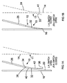
- FIGS 1A and 1B show a turnout with two prior art switching devices 10, 11.
- a turnout comprises a first railway track which has two running rails. It will be appreciated that trains can be driven in either of two directions along a railway track.
- Figures 1A and 1B are described below for a train approaching from the bottom of Figures 1A and 1B.
- Figures 1A and 1B show the first track comprises a left running rail 16 and a right running rail 14 (shown with dotted lines).
- Figures 1A and 1B show the left running rail 16 has an inner side 20, which faces the centre of the first track. Flanges of the left wheels of trains are guided by the inner side 20 of the left running rail 16 which receives the front of the wheel flanges.
- One prior art switching device is used for the left running rail 16 and another prior art switching device 11 is used for the right running rail 14.
- the prior art switching device 10 comprises a switch blade 32 that can be moved between an open position shown in Figure 1A and a closed position shown in Figure 1B.
- the other prior art switching device 11 also comprises a switch blade 33 that can be moved between a closed position shown in Figure 1A and an open position shown in Figure 1B. Hence, when one switching device 10, 11 is open, the other switching device 11, 10 is closed.
- Figure 1B shows that when the switch blade 32 is closed, the switching device 10 is used to connect the first track to a diverging second turnout track.
- the turnout track has a left turnout rail 26 and a right turnout rail 24 (shown with dotted lines).
- Figure 1B shows the switch blade 32 connecting the left running rail 16 to the left turnout rail 26. Hence, a passing train continues on the second diverging turnout track when the switching device 10 is closed.
- the switch blade 32 has a back end 34, a front end 36, an inner side 42 and an outer side 40.
- the back end 34 of the switch blade 32 is connected by a hinge 38 to the left turnout rail 26.
- the hinge 38 enables the switch blade 32 to be opened and closed.
- the switch blade 32 closes against the left running rail 16.
- the front end 36 of the switch blade 32 is tapered so it can close against the left running rail 16 more closely.
- a small gap of 12 mm for example
- a facing point lock is necessary to ensure the closed blade 32 does not move away from the left running rail 16 when trains pass over the closed switching device 10. If these locks fail, switches could be thrown as a train passes which could result in derailment. Hence, safety is a serious problem.
- switch blade 32 has a tapered front end 36, it is susceptible to wear and tear on the inner side 42 of switch blade 32. This can result in a change of shape and damage to the switch blade 32. A derailment can then ensue. Hence, derailment is more likely if switch blades 32 are not monitored and replaced when they become too worn.
- Derailment is more likely to occur if there is a gap between the switch blade 32 and the running rail 16 when the switching device 10 is closed.
- the front end 36 of the switch blade does not contact and join the switch blade 32 to the inner side 20 of the running rail 16.
- a gap is created between the inner side 42 of the switch blade 32 and the inner side 20 of the running rail 16. If the switch blade 32 contacts the running rail 16 at a shallow angle, the gap in front of the inner side 42 of the switch blade 32 will be wider. The risk of derailment will be increased if this gap is wider than the width of a train wheel flange.
- switch blades Whilst the switch blade 32 shown in Figures 1A and 1B has straight running edges, switch blades can have a curved inner side 42. However, this arrangement results in the front end 36 of these blades being even thinner which makes it even more difficult to create a strong switch blade arrangement with minimal gap between the switch blade 32 and the running rail 14.
- Switch blades can be made to contact a curved running rail but it is more difficult to achieve close fit between the switch blade and running rail.
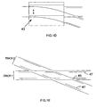
- Early switching device arrangements include a double-edged single switch blade such as the blade illustrated in Figure 1C.
- a long switch blade 35 swings across the first track when the switch is opened and connects with the left running rail 16 thereby connecting the second diverging turnout track to the first track.
- the switch blade is held in the open position as the train passes from the first to the second turnout track, as the switch blade guides the front of the flange of the wheels on the outside of the curve.
- an alternative switching device is based on a movable complete section of track 1 which is called a traverser turnout 43 illustrated in Figure 1D.
- a traverser turnout 43 illustrated in Figure 1D.
- This is used on some rack and pinion railways in Switzerland.
- the moveable section of track 43 is sometimes forced towards the open position when trains pass and sometimes towards the closed position.
- derailment protection depends totally on the point lock and hence this mechanism is not intrinsically safe.
- the movable section of track is also operated by a sliding mechanism, which requires a substantial amount of power to move the track.
- switch blade turnouts being unsafe. Wear and tear of switch blades increases the risk of derailment. This risk can be reduced by decreasing train speed at turnouts, but this lengthens train journey times.
- Other known switching devices such as the traverser turnout 43 are prohibited for passenger use in the UK as they are held in position by locks alone.
- Switching devices are also used at crossings.
- a crossing a first track crosses over a second track, but trains can continue on the track they were previously on. This is made possible by having gaps in the rails at the crossing.
- An example of such gaps can be seen at 45 in Figure IE.
- trains usually cross crossings at reduced speed, which again increases journey times.
- check-rails 47 are needed to prevent derailment as train wheel flanges pass through the gaps.
- a switching device for connecting railway track or tracks in more than one configuration comprising:
- a variety of guide means may be used to guide the base along this path.
- the guide means may guide the base along a substantially cycloidal path between the first and second positions.
- the guide means includes a frame which is carried on front and rear wheel pairs, each wheel being connected to the base by a connecting member extending from the base to an off axis position on each wheel.
- the wheels of these embodiments may have teeth.
- the wheels of some of these embodiments may have teeth which engage with teeth of a gear track to provide a rack and pinion mechanism.
- the guide means includes wheels with teeth which engage with a chain to provide a chain and sprocket mechanism.
- the guide means comprises at least one four bar linkage which guides the base between the first and second positions.
- the four bar linkage may guide the base between the first and second positions along a circular arc path.
- At least one of the track connecting portions may have ends which are adapted to mate with the track it connects. This arrangement reduces gaps between the track connecting portion and the track it connects.
- At least one of the track connecting portions may have sides which are curved. This arrangement is useful for connecting curved tracks.
- a guide rail may also be mounted to the base plate.
- the guide rail may be in the form of a conventional guide-rail or a check-rail. This arrangement allows the front and/or back of wheel flanges of a train to be guided as a wheel flange passes over the switching device.
- the first track connecting portion and second track connecting portions may be mounted on the base plate so that they connect tracks at different heights. This arrangement is useful for connecting tracks with a cant.
- each connecting portion can be replaced separately. This arrangement is useful if only one connecting portion becomes worn and needs replacing.
- Switching devices in accordance with embodiments of the present invention are described below for connecting railway tracks at turnouts and crossings. Whilst these embodiments are described for tracks with two running rails, it will be appreciated that they can be used to connect monorail tracks.
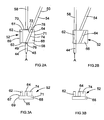
- Figures 2A and 2B show a turnout having a switching device in accordance with an embodiment of the present invention.
- the turnout comprises a first railway track which has two running rails. It will be appreciated that trains can be driven in either of two directions along this track.
- Figures 2A and 2B are described below for a train approaching from the bottom of Figures 2A and 2B.
- the first track has a left running rail 44 and a right running rail (not shown).
- the left running rail 44 has an inner side 48 which faces the centre of the first track and an outer side 49, which faces away from the centre of the first track.
- the running rail 44 receives the front of flanges of a train wheel on the inner side 48 of the rail 44.
- FIGS 2A and 2B show the left running rail 44 is coupled to the switching device 52.
- the switching device 52 can be moved between a first position ( Figure 2A) and a second position ( Figure 2B).
- Figure 2A shows that when the switching device 52 is in the first position, the first track is connected so it continues on a diverging second track on a left turnout rail 54 and a right turnout rail (not shown). Hence the switching device 52 is "set for the turnout" when it is in the first position.
- Figure 2B shows that when the switching device 52 is in the second position, the first track is connected so it continues on a straight path on a left through route rail 58 and a right through route rail (not shown). Hence, the switching device 52 is "set for the through route" when it is in the second position.
- Figures 2A, 2B, 3A, and 3B and Figure 4 show the switching device 52 generally comprises a base plate 66 on which are mounted a through switch rail 62, and a turnout switch rail 64.
- the switching device 52 has a front end and a back end.
- the base plate 66 has a first end 68, a second end 70, a left side 69, a right side 71, a top 67 and a bottom 65.
- the turnout switch rail 64 has an outer side 72 and an inner side 74, a front end 76 and a back end 78.
- the front end 76 is arranged so it is substantially parallel with the first end 68 of the base plate 66.
- the back end 78 is arranged so it is substantially parallel with the second end 70 of the base plate 66.
- the through switch rail 62 has a front end 63, back end 61 and two sides.
- the switch rails 62, 64 are mounted at least the width of a train wheel flange apart on the base plate 66.
- the turnout switch rail 64 and through switch rail 62 are mounted on the base plate 66 of the switching device 52 to enable the position of both the turnout switch rail 64 and the through switch rail 62 to be changed between the first and second positions.
- the turnout switch rail 64 connects the left running rail 44 to the left turnout rail 54. Hence the front of the wheel flanges are guided by the rails 44, 64, 54 on to the second diverging track.
- the front end 76 of the turnout switch rail 64 is parallel with the first end 68 of the base plate 68 so the turnout switch rail 64 can couple with the left running rail 44.
- the back end 78 of the turnout switch rail 64 is parallel with the second end of the base plate 70, so the turnout switch rail 64 can couple with the left turnout rail 54.
- the sides 72, 74 of the turnout switch rail 64 are at an angle to the front 76 and back 78 ends so they can connect the left running rail 44, to the left turnout rail 54 of the diverging second track.
- the through switch rail 62 connects the left running rail 44 to the left through route rail 58.
- the switch rails 62, 64 are mounted apart so wheel flanges can pass between them when the switching device is in this position.
- the base plate 66 is operatively coupled to a guide means for controlling movement of the switching device 52 between the first position shown in Figure 2A and the second position shown in Figure 2B.
- the guide means comprises a frame, a first gear wheel 88, a second gear wheel 90 and two other gear wheels.
- the frame comprises a first arm 92 and a second arm.
- the frame is connected to a driving shaft.
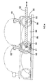
- Figure 4 is a schematic view of a section of the switching device 52 and shows the first arm 92 of the frame, the first gear wheel 88 and the second gear wheel 90 of the guide means.
- Each of the gear wheels 88, 90 are connected to the base plate 66 by a connecting member extending from the base plate 66 to an off axis position on each wheel 88, 90.
- the connecting members are a first pin 84, a second pin 86 and two further pins (not shown) which are each mounted on the base plate 66.
- the first pin 84 and second pin 86 are mounted on the first end 68 of the base plate 66 as shown by Figure 4.
- Figure 4 shows the first gear wheel 88 has a first axle 91.
- the second gear wheel 90 has a second axle 93.
- the axles 91, 93 are mounted on the first arm 92 of the frame.
- the first gear wheel 88 has an inner circumferential surface and an outer circumferential surface. The inner circumferential surface is closer to the wheel's axle 91 than the outer circumferential surface.
- Each of the gear wheels 88, 90 has gear teeth. The gear teeth are located on the outer circumferential surface of each wheel.
- the first gear wheel 88 has a receiving portion.
- the receiving portion is at a position offset from the axle 91 of the gear wheel 88.
- the receiving portion is on the inner circumferential surface of the gear wheel 88.
- the second gear wheel 90 has the same arrangement.
- the first pin 84 of the base plate 66 engages with the first gear wheel 88.
- the first pin 84 engages with the receiving portion on the gear wheel 88.
- the second pin 86 engages with a second gear wheel 90 in the same manner.
- the other two gear wheels have the same structure as the first 88 and second 90 gear wheels and are mounted on the second arm of the frame and couple with the two other pins (not shown) of the base plate 66 as described above for Figure 4.
- the two further pins are mounted on the second end 70 of the base plate 66.
- the gear wheels 88, 90 are each arranged to run along a gear track 89.
- the gear track is arranged below the base plate 66.
- the gear track 89 is wide enough so the base plate 66 is above the gear track 89 when the base plate 66 is in the first position shown in Figure 2A and when the base plate 66 is in the second position shown in Figure 2B.
- the gear track 89 has rack teeth.
- the gear wheels 88, 90 each engage with the gear track 89.
- the teeth of the first gear wheel 88 engage with the rack teeth of the gear track 89.
- the teeth of the second gear wheel 90 engage with the rack teeth of gear track 89.
- the gear wheels 88, 90 on the first arm 92 and the other two gear wheels on the second arm of the frame guide the base plate 66 co-operatively.
- the guide means guides the switching device 52 when the frame and thus the first arm 92 and second arm are moved.
- the driving shaft of the frame is driven by a driving means (not shown) which can move the frame horizontally in a reciprocating manner.
- the first arm 92 can move in a first direction to the right of Figures 4 and 5 or a second direction to the left of Figures 4 and 5.
- the second direction being opposite to the first direction.
- the switching device 52 When the first arm 92 is moved in the second horizontal direction, the switching device 52 is moved from the second position (shown in Figure 2B, Figure 4 (with solid lines) and Figure 5C) to the first position (shown in Figure 2A, Figure 4 (with dotted lines) and Figure 5A). Movement of the first arm 92 in the second horizontal direction, causes the gear wheel axles 91, 93 to also move in the same second horizontal direction (to the left of Figures 4 and 5).
- the gear wheels 88, 90 act as pinions and engage with the gear track 89 which acts as a rack. Hence, the movement of the gear wheel axles 91, 93 in the second horizontal direction causes the gear wheels 88, 90 to rotate anticlockwise and roll to the left of Figure 4 along the track 89.
- the rotating gear wheels move the base plate 66 pins 84, 86 and hence the base plate 66.
- the guide means co-operates with the driving means to enable the base plate 66 to be moved along a cycloidal path (indicated by the dotted line in Figure 4) between the first and second positions.
- the base plate 66 is thus initially moved upwardly and to the left of Figure 4. This means the base plate 66 is moved along a path which has both vertical and horizontal components.
- the base plate 66 When the base plate 66 is at this top of the cycloidal path, the base plate 66 can drop into either the first or the second position, as indicated by the double headed arrow in Figure 5B. Continued movement of the first arm 92 in the second horizontal direction to the left of Figure 4 causes the base plate 66 to drop into the first position.
- the base plate 66 can then be moved from the first position along the same cycloidal path and returned to the second position (shown in Figure 2B, Figure 4 (with solid lines) and Figure 5C) if the driving means is then operated to move the first arm 92 of the frame of the guide means in the first horizontal direction (i.e. to the right of Figures 4 and 5).
- the turnout switch rail 64 connects the left running rail 44 to the left turnout rail 54.
- the guide means is coupled with the base plate so that when the switching device 52 is moved between the first and second positions, the switching device is guided along a path which has both vertical and horizontal components.
- the four pins 84, 86, frame and four gear wheels 88, 90 are arranged so the switching device can move between the first and second position along a path which has both vertical and horizontal components.
- the guide means guides the switching device 52 along a cycloidal path between the first and second positions as shown by Figures 4 and 5.
- the four pins 84, 86, frame and four gear wheels 88, 90 are arranged to guide the switching device 52 along the cycloidal path.
- the switching device 52 When the switching device 52 is in the first position indicated with dotted lines in Figure 4, it is resistant to movement in the first or second horizontal direction (i.e. to the left or right of Figure 4) as the switching device 52 is guided along the path which has both horizontal and vertical components.
- switching device 52 when the switching device 52 is in the first position, the switching device 52 is resistant to movement in a direction with only horizontal components. This means the switching device 52 can only be lifted out of the first position. For the same reasons, switching device 52 is resistant to purely horizontal movement when it is in the second position shown in Figure 2B.
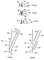
- FIGS. 6A and 6B show a modified form of switching device 53 used in a slightly different turnout.
- Figures 6A and 6B show the right running rail 46 of the first track shown in Figures 2A and 2B and the first track and diverging track also have check-rails which are not present in Figures 2A and 2B.
- Figures 6A and 6B show a running check-rail 116 is provided for the right running rail 46.
- a turnout check-rail 118 is also provided for the right turnout rail 56.
- the right turnout rail 56 has an inner side 57 which faces towards the centre of the diverging track.
- the right running rail 46 has an inner side 51 which faces towards the centre of the first track.
- the check-rails 116, 118 are arranged so they are opposite the inner side 51 of the right running rail 46 and the inner side 57 of the turnout rail 56 respectively
- FIGS 6A and 6B show the switching device 53 is connected to the right running rail 46.
- the switching device 53 is identical to the switching device 52 shown in Figures 2A and 2B, but it also includes a check switch rail 120.
- the check switch rail 120 is mounted on the base plate 66.
- the check switch rail 120 is mounted on the base plate 66 between the through switch rail 62 and the turnout switch rail 64.
- the check switch rail 120 is substantially parallel to the turnout switch rail 64.
- the check switch rail 120 and the turnout switch rail 64 are mounted at least a wheel flange width apart.
- FIG. 6A and 6B Another switching device 53 with a similar check-rail arrangement to that shown in Figure 6A and 6B can be used as a switching device 53 for the left running rail 44.
- a check-rail can be used with the switch rail 62 and through route running rail 60 if the through route also requires a check-rail.
- FIG. 6A shows the switching device 53 set for turnout route.
- the switch check-rail 120 connects the running check-rail 116 and the turnout check-rail 118.
- flanges of the right wheel of the train are guided between the right running rail 46 and the running check-rail 116.
- the wheel flanges are guided between the turnout switch rail 64 and the switch check-rail 120.
- wheel flanges are guided by the right turnout rail 56 and the turnout check-rail 118.
- the switch check-rail 120 can also function as a turnout switch check-rail if a train approaches the switching device 53 from the opposite direction.
- Figure 7 shows a switching device 122 in accordance with an embodiment of the present invention which is used at a crossing.
- a first track intersects with a second track.
- the first track has a first left running rail 130 and a second left running rail 132 and a first right running rail (not shown) and a second right running rail (not shown).
- the second track has a first right running rail 138 and a second right running rail 140 and a first left running rail (not shown) and a second left running rail (not shown).
- Figure 7 only shows the running rails 130, 132, 138, 140 of each track.
- the switching device 122 is movable between a first position and a second position. When the switching device 122 is in a first position shown in Figure 7, a train can continue on the first track. When the switching device is in a second position shown with dotted lines in Figure 7, a train can continue on the second track.
- the switching device 122 generally comprises a first switch rail 148, a second switch rail 150 and a base plate 66. Each of the switch rails 148, 150 are mounted on the base plate 66.
- the base plate 66 has a structure similar to that of the base plate 66 shown in Figure 4 and has the same guide means, driving shaft and driving means.
- the second switch rail 150 has a front end 151, a back end 149 and two sides.
- Figure 7 shows the first switch rail 148 has two sides 152, 154, a front end 156 and a back end 158.
- the front end 156 is substantially parallel to the first end 68 of the base plate 66.
- the back end 158 is substantially parallel to the second end 70 of the base plate 66.
- the switching device 122 When the switching device 122 is in the first position shown in Figure 7, the switching device 122 connects the first track.
- the first switch rail 148 connects the first left running rail 130 to the second left running rail 132.
- the switching device 122 When the switching device 122 is in the second position (shown with dotted lines in Figure 7), the switching device 122 connects the second track. In this position, the second switch rail 150 connects the first right running rail 138 to the second right running rail 140.
- the switch rails 148,150 are mounted on the base plate 66 of the switching device 122 to enable the position of both the switch rails 148, 150 to be changed between the first and the second positions. Movement between the first and second positions is effected in the same way as that of the first embodiment of the present invention 52.
- the first track and the second track cross over each other at an angle to form a diamond shape as shown in Figures 8A and 8B.
- the diamond shape created where the first and second tracks cross has two corners with acute angles 168, 169 and two corners with obtuse angles 170, 171 as shown in Figures 8A and 8B.
- Figures 8A and 8B show it is possible to use the switching device 122 at each of these corners 168, 169 170, 171.
- switch rails 64, 62 of the switching devices 52, 53 described above with sides 72, 74 that are curved to enable the switch rails 64, 62 of the switching devices 52, 53 described above to tangent a curved track more smoothly.
- the sides of switch rails 150, 148 could be curved for connecting curved tracks at crossings.
- switch rails 148, 150 of the switching device 122 do not need to be mounted at the same height on the base plate 66. This enables the switching device 122 to connect tracks which have a cant at a crossing. Switching devices 52, 53, 122 with rails for canted tracks provide improved safety. Any of switch rails 62, 64, 148, 150 can be mounted so they are not parallel to the top 67 of the base plate 66. Mounting the switch rail 62, 64, 148, 150 in this way, enables the switch rail 62, 64, 148, 150 to connect two track rails which are at different heights.
- the switch rails 62, 64, 148, 150 can connect track in a variety of ways.
- the switch rails 62, 64 may be arranged at different angles to each other on the base plate 66. It is preferable that there is no gap between the switch rails 62, 64 and the track rails they connect. Likewise, it is preferable that there is no gap between switch rails 148, 150 and the track rails they connect. Gaps can be minimised as the ends 61, 63, 76, 78, 149, 151, 158, 156 of switch rails can be arranged at an angle to enable them to engage with track rails.
- the ends of the switch rails do not need to be tapered, they are stronger and can therefore be arranged to minimise gaps between the switch rails and track rails. Minimising gaps reduces danger of obstruction and makes the switching device 52, 53, 122 more resistant to wear and tear. It also makes the ride more pleasant when a train passes over the switching device 122. Noise is also reduced when trains pass over the switching device 122 due to minimal gaps between the switch rails and track rails at a crossing. As switch rails 62, 64, 148, 150 can mate with track rail, this reduces track alignment problems. Guide rails 120 like those described for the switching device 53 can also be used for switching devices 122 used at crossings.
- the switch rails 62, 64, 148, 150 can be detachably mounted to the base plate 12 to enable the rails to be replaced independently. This eases maintenance of the switching devices 52, 53, 122.
- the fact that the weight of trains can be used to keep the switching devices 52, 53, 122 in position minimises the chance of the switching devices 52, 53, 122 moving out of position accidentally.
- Facing point locks can be attached to lock switching devices 52, 53 and switching devices 122 to provide an additional means of ensuring the switching devices 52, 53, 122 are held in position.
- Other known locking devices may also be used if preferred.
- Gear wheels 88, 90 can be arranged within the base plate 66. It may be desirable to couple the guide means to the base plate 66 at several locations.
- the frame can have more than two arms 92. More than two gear wheels 88, 90 can be mounted on an arm 92 of the guide means.
- the gear wheels 88, 90 may act as sprockets and engage with a chain rather than the toothed gear track 89 described above.
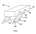
- FIG. 9 shows a switching device in accordance with an alternative embodiment of the present invention in which the switching device 52 of Figures 2A and 2B is guided by a four bar linkage arrangement rather than the guide means shown in Figure 4.
- the four bar linkage arrangement comprises the base plate 66, two bars 100, 104, a mount 102 and four pins 84, 86, 106, 108.
- the first pin 84 is coupled to a first bar 100.
- the first bar 100 is coupled to the mount 102.
- the first bar 100 and the mount 102 are coupled by a third pin 106.
- the second pin 86 is coupled to a third bar 104.
- the third bar 104 and the mount 102 are coupled by a fourth pin 108.
- Another identical four bar linkage is arranged on the second end 70 of the base plate 66.
- the mount 102 anchors the four bar linkage during operation.
- the four bar linkage arrangement is operatively coupled to a driving shaft (not shown) and the driving shaft is driven by a driving means (not shown).
- the driving means moves the driving shaft in the horizontal reciprocating manner as described for Figures 4 and 5 and both four bar linkages guide the base plate 66 co-operatively.
- the four bar linkage guides the base plate 66 so it moves along a circular arc.
- the four bar linkage arrangement ensures switching device 52, 53, 122 is guided along a path which has both vertical and horizontal components. Hence, it is difficult to move the switching device 52, 53, 122 accidentally to the left or right of Figure 2A when it is in the first position shown in Figure 2A or when it is in the second position shown in Figure 2B.
- the switching device 52, 53, 122 is also held in position by the weight of the train as described above.
- More than two four bar linkages may be used.
- the four bar linkages can be mounted to the base plate 66 using alternative means. It is not necessary to mount them to the ends 68, 70 of the base plate 66. Additional bars may link the base plate 66 to the mount 102. This improves stability of the base plate 66.
- the driving shafts are driven by an air cylinder driving means.
- switching devices 52, 53, 122 each drop into either the first or the second position from the position shown in Figure 5B, very little power is needed for the driving means as the switching devices 52, 53, 122 have no sliding parts.
- the driving means can be replaced with different driving means known in the art.
- the driving means can be improved using commonly known techniques. For example a counter balance spring or a counter balance deadweight can be used to reduce the driving force needed and accelerate operation.
- alternative guide means and/or driving means can be used to move the base plate 66 along the path having both vertical and horizontal components as described above.
- Alternative straight driving means can be used.
- the driving means can be an electrical, pneumatic or hydraulic driving means. Manual means can also be employed to "throw" the switches. Whilst the driving shafts are driven in a horizontal direction and operate on the guide means to produce the desired movement, a standard rotary driver arrangement with different guide means can also be used to produce this movement.
Landscapes
- Engineering & Computer Science (AREA)
- Mechanical Engineering (AREA)
- Architecture (AREA)
- Civil Engineering (AREA)
- Structural Engineering (AREA)
- Railway Tracks (AREA)
- Train Traffic Observation, Control, And Security (AREA)
Applications Claiming Priority (1)
| Application Number | Priority Date | Filing Date | Title |
|---|---|---|---|
| GB0610534A GB0610534D0 (en) | 2006-05-26 | 2006-05-26 | Device for connecting railways |
Publications (2)
| Publication Number | Publication Date |
|---|---|
| EP1860238A2 true EP1860238A2 (fr) | 2007-11-28 |
| EP1860238A3 EP1860238A3 (fr) | 2008-11-19 |
Family
ID=36687836
Family Applications (1)
| Application Number | Title | Priority Date | Filing Date |
|---|---|---|---|
| EP07252121A Withdrawn EP1860238A3 (fr) | 2006-05-26 | 2007-05-23 | Dispositif pour raccorder des voies ferrées |
Country Status (2)
| Country | Link |
|---|---|
| EP (1) | EP1860238A3 (fr) |
| GB (1) | GB0610534D0 (fr) |
Cited By (4)
| Publication number | Priority date | Publication date | Assignee | Title |
|---|---|---|---|---|
| CN102951432A (zh) * | 2012-10-18 | 2013-03-06 | 上海德马物流技术有限公司 | 滑块式分拣机内的中置自动道岔换向装置 |
| CN110886159A (zh) * | 2019-12-16 | 2020-03-17 | 中建空列(北京)科技有限公司 | 基于多道岔结构的双线双开轨道梁和悬挂式空铁系统 |
| US11155967B2 (en) | 2016-04-13 | 2021-10-26 | Pandrol Limited | Swing turnout for railroad tracks and method for providing a turnout |
| CN118811397A (zh) * | 2024-09-14 | 2024-10-22 | 意锐科(宁波)智能科技有限公司 | 一种轨道变轨切换机构 |
Family Cites Families (3)
| Publication number | Priority date | Publication date | Assignee | Title |
|---|---|---|---|---|
| US1388700A (en) * | 1921-05-05 | 1921-08-23 | Cwojna Albert | Railway-switch |
| DE2247551A1 (de) * | 1972-09-28 | 1974-04-11 | Krupp Gmbh | Weiche mit horizontal beweglichem weichenteil, insbesondere fuer schwebefahrzeuge |
| CA2165835C (fr) * | 1993-07-13 | 2003-12-16 | Arthur Ernest Bishop | Aiguilles pour systeme automatise de transport sur rails |
-
2006
- 2006-05-26 GB GB0610534A patent/GB0610534D0/en not_active Ceased
-
2007
- 2007-05-23 EP EP07252121A patent/EP1860238A3/fr not_active Withdrawn
Cited By (5)
| Publication number | Priority date | Publication date | Assignee | Title |
|---|---|---|---|---|
| CN102951432A (zh) * | 2012-10-18 | 2013-03-06 | 上海德马物流技术有限公司 | 滑块式分拣机内的中置自动道岔换向装置 |
| CN102951432B (zh) * | 2012-10-18 | 2016-02-17 | 上海德马物流技术有限公司 | 滑块式分拣机内的中置自动道岔换向装置 |
| US11155967B2 (en) | 2016-04-13 | 2021-10-26 | Pandrol Limited | Swing turnout for railroad tracks and method for providing a turnout |
| CN110886159A (zh) * | 2019-12-16 | 2020-03-17 | 中建空列(北京)科技有限公司 | 基于多道岔结构的双线双开轨道梁和悬挂式空铁系统 |
| CN118811397A (zh) * | 2024-09-14 | 2024-10-22 | 意锐科(宁波)智能科技有限公司 | 一种轨道变轨切换机构 |
Also Published As
| Publication number | Publication date |
|---|---|
| GB0610534D0 (en) | 2006-07-05 |
| EP1860238A3 (fr) | 2008-11-19 |
Similar Documents
| Publication | Publication Date | Title |
|---|---|---|
| US10260202B2 (en) | Railway points, railway points operating apparatus and railway track crossing | |
| EP1860238A2 (fr) | Dispositif pour raccorder des voies ferrées | |
| DE4142914A1 (de) | Biegeweiche | |
| EP1183424B1 (fr) | Bifurcation ferroviaire | |
| US20070007394A1 (en) | System, method, and apparatus for railroad turnout and derail lift frog | |
| EP1169517A1 (fr) | Aiguillage pivotant pour rampe de guidage | |
| CS197310B2 (en) | Railway switch | |
| KR100426522B1 (ko) | 철도 선로 분기 장치 | |
| US795342A (en) | Derailing-switch. | |
| US641952A (en) | Street-railway switching device. | |
| US193206A (en) | Improvement in railroad-switches | |
| JP3153583U (ja) | ノーズ可動クロッシング構造 | |
| US3118642A (en) | Railroad frogs | |
| US765572A (en) | Railroad-switch. | |
| US779695A (en) | Railway-switch. | |
| US792647A (en) | Railway-crossing. | |
| US776692A (en) | Railway-switch. | |
| US162460A (en) | Improvement in railway-switches | |
| US532817A (en) | Railway-switch | |
| US931073A (en) | Railway-frog. | |
| US977116A (en) | Safety-lock for railway-switches. | |
| US330509A (en) | Railroad-switch | |
| US578966A (en) | Railroad-switch | |
| US165287A (en) | Improvement in railway-switches | |
| US328044A (en) | Automatic railway-frog |
Legal Events
| Date | Code | Title | Description |
|---|---|---|---|
| PUAI | Public reference made under article 153(3) epc to a published international application that has entered the european phase |
Free format text: ORIGINAL CODE: 0009012 |
|
| AK | Designated contracting states |
Kind code of ref document: A2 Designated state(s): AT BE BG CH CY CZ DE DK EE ES FI FR GB GR HU IE IS IT LI LT LU LV MC MT NL PL PT RO SE SI SK TR |
|
| AX | Request for extension of the european patent |
Extension state: AL BA HR MK YU |
|
| PUAL | Search report despatched |
Free format text: ORIGINAL CODE: 0009013 |
|
| AK | Designated contracting states |
Kind code of ref document: A3 Designated state(s): AT BE BG CH CY CZ DE DK EE ES FI FR GB GR HU IE IS IT LI LT LU LV MC MT NL PL PT RO SE SI SK TR |
|
| AX | Request for extension of the european patent |
Extension state: AL BA HR MK RS |
|
| RIC1 | Information provided on ipc code assigned before grant |
Ipc: E01B 7/20 20060101ALI20081014BHEP Ipc: B61L 5/00 20060101ALI20081014BHEP Ipc: E01B 7/00 20060101AFI20070906BHEP |
|
| 17P | Request for examination filed |
Effective date: 20090514 |
|
| AKX | Designation fees paid |
Designated state(s): AT BE BG CH CY CZ DE DK EE ES FI FR GB GR HU IE IS IT LI LT LU LV MC MT NL PL PT RO SE SI SK TR |
|
| 17Q | First examination report despatched |
Effective date: 20090707 |
|
| STAA | Information on the status of an ep patent application or granted ep patent |
Free format text: STATUS: THE APPLICATION IS DEEMED TO BE WITHDRAWN |
|
| 18D | Application deemed to be withdrawn |
Effective date: 20091118 |