EP1860239A2 - Wagenverwaltungssystem und Schienenwartungsverfahren - Google Patents
Wagenverwaltungssystem und Schienenwartungsverfahren Download PDFInfo
- Publication number
- EP1860239A2 EP1860239A2 EP07107628A EP07107628A EP1860239A2 EP 1860239 A2 EP1860239 A2 EP 1860239A2 EP 07107628 A EP07107628 A EP 07107628A EP 07107628 A EP07107628 A EP 07107628A EP 1860239 A2 EP1860239 A2 EP 1860239A2
- Authority
- EP
- European Patent Office
- Prior art keywords
- rail
- rails
- track
- running
- management system
- Prior art date
- Legal status (The legal status is an assumption and is not a legal conclusion. Google has not performed a legal analysis and makes no representation as to the accuracy of the status listed.)
- Withdrawn
Links
Images


Classifications
-
- E—FIXED CONSTRUCTIONS
- E01—CONSTRUCTION OF ROADS, RAILWAYS, OR BRIDGES
- E01B—PERMANENT WAY; PERMANENT-WAY TOOLS; MACHINES FOR MAKING RAILWAYS OF ALL KINDS
- E01B23/00—Easily dismountable or movable tracks, e.g. temporary railways; Details specially adapted therefor
-
- A—HUMAN NECESSITIES
- A63—SPORTS; GAMES; AMUSEMENTS
- A63G—MERRY-GO-ROUNDS; SWINGS; ROCKING-HORSES; CHUTES; SWITCHBACKS; SIMILAR DEVICES FOR PUBLIC AMUSEMENT
- A63G21/00—Chutes; Helter-skelters
- A63G21/04—Chutes; Helter-skelters with fixed rails
-
- A—HUMAN NECESSITIES
- A63—SPORTS; GAMES; AMUSEMENTS
- A63G—MERRY-GO-ROUNDS; SWINGS; ROCKING-HORSES; CHUTES; SWITCHBACKS; SIMILAR DEVICES FOR PUBLIC AMUSEMENT
- A63G7/00—Up-and-down hill tracks; Switchbacks
-
- B—PERFORMING OPERATIONS; TRANSPORTING
- B61—RAILWAYS
- B61B—RAILWAY SYSTEMS; EQUIPMENT THEREFOR NOT OTHERWISE PROVIDED FOR
- B61B13/00—Other railway systems
-
- E—FIXED CONSTRUCTIONS
- E01—CONSTRUCTION OF ROADS, RAILWAYS, OR BRIDGES
- E01B—PERMANENT WAY; PERMANENT-WAY TOOLS; MACHINES FOR MAKING RAILWAYS OF ALL KINDS
- E01B23/00—Easily dismountable or movable tracks, e.g. temporary railways; Details specially adapted therefor
- E01B23/02—Tracks for light railways, e.g. for field, colliery, or mine use
- E01B23/06—Switches; Portable switches; Turnouts
-
- E—FIXED CONSTRUCTIONS
- E01—CONSTRUCTION OF ROADS, RAILWAYS, OR BRIDGES
- E01B—PERMANENT WAY; PERMANENT-WAY TOOLS; MACHINES FOR MAKING RAILWAYS OF ALL KINDS
- E01B9/00—Fastening rails on sleepers, or the like
Definitions
- the present invention relates to a cart management system which is installed in regions such as nature reserves, inhabited by animals and plants requiring that extreme care be taken, undeveloped regions difficult for humans to access, and swamps where traffic, such as vehicles, cannot travel, so that sightseeing is made possible without destroying the ecosystem of various resident animals and plants. More particularly, the present invention relates to a cart management system which can also be utilized as leisure sport equipment, by which a user can drive a rail cart using his/her own strength through a scenically beautiful region while enjoying the scenery.
- the inventor has developed Korean Utility Registration No. 368841 , entitled “Manually Controlled Power Train on Railroad” and No. 371751 , entitled “Rail Cart Powered by Wind,” and has been managing such equipment in regions such as Jeong-seon, Gang-won province, Korea.
- Such a rail cart system which is installed to use abandoned railroad tracks and is driven manually without additional power, can attract many tourists to flourish the regional economies because of the various tourists coming and enjoying the manually driving railroad cart system.
- the rail carts of the above type can be managed only in regions where railroad tracks are installed.
- such railroad tracks are mostly single sets of tracks, so that a large number of people cannot drive rail carts without having to wait for a long time.
- the present invention has thus been made to solve the aforementioned problems with the prior art, and an object of the present invention is to provide a tourist system capable of allowing large numbers of tourists to access nature reserves without injuring the ecological systems.
- Another object of the invention is to provide a system capable of allowing easy access to sightseeing areas which are difficult to access and where railroad tracks are not installed, by installing a simple support structure and a rail track and developing carts for driving on the rail track.
- a further object of the invention is to provide a tour cart management system that includes a multiple structure of two or more sets of rail tracks, in which a turntable or a resting place is installed so that tourists can take a rest while enjoying tours on carts.
- Another object of the invention is to provide a tour cart management system including a multiple structure of two or more sets of rail tracks, so that the number of users can be greatly increased without having to destroy nature.
- Yet another object of the invention is to provide a rail system enabling tours and leisure, for which one need not construct a tunnel, build a bridge or remove a protruding part of a mountain for the purpose of road or footpath construction, and in which running rails are installed a preset distance from the ground, which is required in order to conserve nature, thus permitting tourism without injuring the ground, so that the ecological paths of animals can be preserved.
- the cart driving rail system of the invention can be installed in areas having excellent scenery, places where various memorials or educational materials are displayed, nature reserves where wildlife resides and access is restricted, undeveloped areas that are difficult to access, swamps which are difficult to access using typical vehicles and so on, in order to enable tours for various natural resources, animals, plants and educational materials, without having to consume a massive amount of construction costs for road construction and rail installation.
- the invention provides a rail system which is installed a preset distance from the ground so that the rail system does not directly contact the ground or animals/plants in nature reserves.
- the invention provides a rail system that includes turntable structures in specific places so that a cart can reverse its direction or move from one rail to another one if necessary in order to access a desired place, which is an improvement on the a conventional system, in which carts can move only in one direction.
- the invention also provides a rail system which is installed a preset distance from the ground using rails made of square iron pipes, which are suitably bent according to the installation site, and a pillar structure capable of fixing the rails at a specific location in the ground.
- the invention further provides a rail system capable of allowing tours regardless of obstacles such as swamps, steep slopes and rivers, using a pillar structure to fix rails above the swamp, an additional support structure to support rails on the steep slope, or a simple reinforcement structure attached to the edge of a bridge in the case of a river.
- FIG. 1 is a schematic view illustrating the rail system of the invention installed around a lake;
- FIG. 2 is a cross sectional view illustrating a rail track of the invention
- FIG. 3 is a plan view illustrating the rail track of the invention.
- FIG. 4 is a cross sectional view illustrating a flat rail track of the invention, which is installed directly on the ground;
- FIG. 5 is a side elevation view illustrating the rail system of the invention installed in an area of uneven ground;
- FIG. 6 is a cross sectional view illustrating a light road crossing structure installed at a road crossing
- FIG. 7 is a cross sectional view illustrating carts traveling on the light road crossing structure installed at a road crossing
- FIG. 8 is a cross sectional view illustrating a heavy road crossing structure installed at a road crossing
- FIG. 9 is a perspective view illustrating a common joining block of the invention.
- FIG. 10 is a perspective view illustrating a repair joining block of the invention.
- FIG. 11 is a front elevation view illustrating a repair rail of the invention.
- FIG. 12 is a cross sectional view illustrating running rails of the invention, which are installed on a bridge;
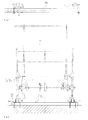
- FIG. 13 is a front elevation view illustrating a turntable of the invention.
- FIG. 14 is a side elevation view illustrating the turntable of the invention.
- FIG. 15 is a plan view illustrating the turntable of the invention.
- FIG. 16 is a cross sectional view illustrating the rail track of the invention installed water body
- FIG. 17 is a cross sectional view illustrating the rail track of the invention installed over a water body
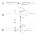
- FIG. 18 is a process view illustrating the procedure for repairing a rail track in case of damage thereto;
- FIG. 19 is a plan view illustrating a cart wheel running toward a rail track joint of the invention.
- FIG. 20 is a plan view illustrating the cart wheel running on a rail track joint of the invention.
- FIG. 21 is a process view illustrating the procedure of assembling the rail track of the invention.
- an exemplary embodiment of the invention includes a track 100 having rails installed directly on the ground or at a preset distance from the ground, a turntable 200 provided at a preset position in the track 100 to allow a cart running on the track 100 to be turned around, a road crossing structure 300 configured to cross a road and the like, on which heavy objects such as vehicles travel, a waterside track 400 installed near a water body, such as a river or a lake, and a cart storage unit 600.
- FIG. 5 is a side view illustrating the track of the invention installed on an area of uneven ground.
- the adjustable rails are installed on ground which is not flat but is uneven, that is, has height differences
- holders for fixing the rails 50 to pillars 1 are adjusted in position to make the rails parallel with the horizon.
- Sinkage prevention plates 3 are provided to prevent the pillars 1 from sinking into the ground.
- the sinkage prevention plates 3 have a wide and planar base structure to prevent sinking.
- ties are installed directly on the ground without the use of additional pillars, and then the rails are installed on the ties.
- auxiliary bases are installed to prevent deformation of the rails.
- ties 7a made of wood members or steel pipes are installed at a preset interval, and the rails 50 are seated on and fixed to the ties 7a using fixing bolts 8 and coupling nuts 9.
- This installation technique is used to directly install the rails on ground which is relatively flat, in which case the rails are not deformed much by the running of the carts.
- the rails 50 are cut to have inclined sections at each end thereof, as shown in FIG. 11, and a joining block 13 such as that shown in FIG. 9 is inserted into one rail 50 through the inclined section (see FIG. 21). Then, as shown in FIG. 21, the joining block 13 is assembled with the rail 50 by using a bolt engaged with a nut so that the bolt extends through an assembly hole 32 in the joining block and an assembly hole 51 in the track rail, and the holders 5 for fixing the rails to the pillars 1 are assembled therewith.
- an indentation 13a is formed in the bottom wall of the joining block to form a rainwater drain path when assembled. Then, rainwater that enters the space inside the rail can be drained out through the rainwater drain path defined by the indentation 13a.
- the turntable 200 is configured to allow a cart to be moved to another track without having to obstruct a following running cart, by which a user can drive the cart to a resting place R as shown in FIG. 1 to take a rest for a while, or can turn the cart around to run in the opposite direction.
- the turntable 200 has turntable rails 210 fixed to respective running rails 211 by locking devices 212, as shown in FIG. 14, in order to allow a cart C running on the rail to be turned around.
- Each of the turntable rails 210 is provided at a lower central portion thereof with a rotation shaft 220, and is configured to be rotatable around the rotation shaft 220.
- the turntable rail 210 in a turned position, can be moved toward an adjacent rail, indicated by the arrow D, by an additional conversion rail 215.
- the locking device 212 installed between the turntable rail and the running rail is locked and unlocked using a lock 214 connected with a lever 202 of a handle 201.
- the lock When the user pulls the lever 202, the lock, connected to the lever, moves back to unlock the locking device 212.
- the locking device 212 is locked when the lever 202 is returned to its original position.
- the locking technique using the lever can be replaced by an electronic control system having a magnetic clutch or a mechanical control system having a gear assembly. It will be appreciated that any structure implementing the locking and unlocking can be adopted as long as it works and can endure outdoor conditions.
- the locking device 212 In the case where it is desired to drive the cart on the running rails installed in the resting place R, the locking device 212 is unlocked and the turntable rails are turned to face the resting place, as indicated by the arrow 250 in FIG. 15.
- the cart C is moved, as indicated by the arrow D, from the rails on which it is currently running to the resting place.
- the above procedures are repeated to move the cart to the running rails again so that the cart runs on the running rails again.
- the road crossing structure 300 is as shown in FIGS. 6 to 8, and is installed at a place where the track crosses an existing road or footpath.
- the road crossing structure 300 is configured to allow free passage to vehicles, other carts, pedestrians and the like who cross over the running rails and to sustain the impact applied to the running rails under the weight of the vehicles without being deformed.
- the road crossing structure 300 is installed differently corresponding to the load encountered at different installation places. That is, a place where vehicles cross places a larger load on the road crossing structure 300 than a place where pedestrians cross.
- FIG. 6 shows a light road crossing structure installed in a place where the track crosses a footpath or a cycle path where relatively lighter objects, such as pedestrians or bicycles, cross.
- the road crossing structure has U-shaped support structures 8 installed in the ground 2, each of the support structures 8 being open upward and implemented as a U-shaped gutter.
- FIG. 8 shows a heavy road crossing structure installed in a place where the track crosses a road for relatively heavier objects such as vehicles.
- the road crossing structure has bases 6 installed to support the entire bottom of the running rails.
- vertical and horizontal reinforcement members 9 and 9a are provided in each of the bases 6.
- the rail 50 is installed so as to be connected to a linking member 5c of the pillar 1 by a connector 9b.
- This structural feature acts to prevent a heavy object such as a vehicle from directly contacting the rails 50 as well as to disperse and remove a large vertical load using the vertical and horizontal reinforcement members 9 and 9a and the bases 6.
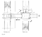
- the waterside track 400 of the invention is installed beside a water body such as a river or lake, and in particular, on a slope, or at least partially fixed underwater.
- the waterside track 400 also includes a bridge crossing a river. The installation position of the waterside track 400 will be described below with reference to FIGS. 16 and 17.
- FIG. 16 shows a row of pillars installed underwater
- FIG. 17 shows both rows of pillars installed underwater.
- a row of pillars on the ground is provided with sinkage prevention plates, which are stuck in the ground.
- underwater pillars 410 are provided to support the corresponding rail.
- the underwater pillars can be implemented with or fixed by wood pillars, iron frames or iron frame concrete structures which are rust-resistant, such as those commonly used in bridges and engineering work.
- both rows of pillars are installed underwater and can be implemented with or fixed using wood pillars, iron frames or iron frame concrete structures, which are rust-resistant.
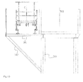
- Another embodiment of the waterside track of the invention can be realized using a simple additional structure in a swamp or lake so that the running rails can be installed without causing interference to pedestrians or vehicles crossing an existing bridge on the swamp or lake.
- an extension 301 is fastened to the edge of an existing bridge 500, and is supported by a reinforcement 302 braced against a pillar 501 of the bridge 500.
- the running rails of the rail track 50 are installed on the extension 301, so that carts can travel along the rail track 50.
- This aspect of the invention allows the running rails to be installed on an existing structure, such as an overpass or a bridge, so that the tour carts can drive on the rails as desired.
- joints of the running rails are slanted in order to suppress vibration and noise occurring at the joints of the running tracks, thereby greatly improving driving comfort.
- the assembly contact surfaces of the running rails are cut at an angle of 45°, thereby forming inclined sections 12 and 12a.
- the inclined sections 12 and 12a of joining rails are formed to match each other, and a joining block 13 is inserted into the joining rails through the inclined sections 12 and 12a. Then, the joining block 13 is assembled with the joining rails to provide smooth running rails to afford smooth cart driving.
- the running rails are implemented as hollow iron members, unlike conventional rails, and thus can be easily installed, disassembled and modified.
- curved rails can be modified before installation so as to match various conditions at installation sites.
- the joining block 13 is used to assemble the rails with 45° inclined sections. Furthermore, the invention also proposes a cutting and replacement structure, by which a broken or damaged rail can be easily cut or removed from the rail track and a new rail can be easily installed.
- the damaged rail track can be repaired by following procedures of:
- the height of pillars for curved running rails can be adjusted according to the direction and degree of curves to the outer circumference of the rails in order to obtain a suitable inclination angle, thereby helping the cart safely and stably drive along the curved rail track.
- the running rails of the invention are designed such that vertical positions of the holders and the pillars can be adjusted in order to properly disperse vertical and lateral weight caused by the radius of the curve.
- a further aspect of the invention serves to overcome the drawback in which it is difficult for carts to run on the rails when the top surface of the rails freezes, by providing slits in the top surface of the rails in the direction perpendicular to the running direction (i.e., perpendicular to the longitudinal direction of the rail).
- the slits may include small protrusions or indentations on the top surface of the rails to create a suitable level of frictional force with the drive wheels of the carts when they contact the slits in order to ensure safe driving.
- Another aspect of the invention is to provide sensors at specific points along the rails to detect the passage of carts. In this way, when a sensor detects a cart arriving at a specific place, it is possible to make an announcement to the cart about the name of the place, tell stories associated with the place, describe famous sights, and so on.
- the tour and leisure cart management system of the invention may be installed generally in famous sightseeing areas, nature reserves, wildlife preserves and the like, guidance and publication for regional development and sightseeing tours can be provided, focusing on animals/plants inhabiting the corresponding region and on various information pertaining to the corresponding region.
- the pillars or sinkage prevention plates need not be installed, but common iron pipes are arranged sequentially to support rails, thereby constructing ties 7a (see FIG. 4), and then rails can be fixed onto the ties 7a.
- auxiliary pillars 1a are provided to the pillar rows to ensure reinforcement.
- the auxiliary pillars are shown in FIG. 5, or may be installed to be suitable for installation sites in the case of a steep slope, as shown in FIG. 16.
- the installation operation of the invention can be carried out while retaining the wilderness and natural environments, unlike in conventional railroad or road construction, and furthermore, the rail system can be installed so that it does not contact the ground, merely using pillars.
- This arrangement basically prohibits tourists from contacting the ground in order to prevent damages to natural areas. This can satisfy both the need to preserve nature and the need to stimulate tourism based on the natural areas, thereby ensuring tax revenues for local governments while enabling the preservation of nature.
- the invention uses a cart system capable of operating without a power supply (e.g., electricity and gasoline), and thus is easily installed in remote areas. Furthermore, no complicated mechanism or process is needed to manage the cart system.
- a power supply e.g., electricity and gasoline
- the cart system is driven manually, slight deformation or distortion of the rails may make driving difficult.
- the rails are connected together at a slight angle so that the deformation or distortion of the rails does not obstruct driving.
Landscapes
- Engineering & Computer Science (AREA)
- Mechanical Engineering (AREA)
- Architecture (AREA)
- Civil Engineering (AREA)
- Structural Engineering (AREA)
- Transportation (AREA)
- Platform Screen Doors And Railroad Systems (AREA)
- Road Paving Structures (AREA)
Applications Claiming Priority (1)
| Application Number | Priority Date | Filing Date | Title |
|---|---|---|---|
| KR1020060045762A KR100702617B1 (ko) | 2006-05-22 | 2006-05-22 | 관광 레져용 카트 운행 시스템 및 레일트랙 보수방법 |
Publications (3)
| Publication Number | Publication Date |
|---|---|
| EP1860239A2 true EP1860239A2 (de) | 2007-11-28 |
| EP1860239A8 EP1860239A8 (de) | 2008-01-02 |
| EP1860239A3 EP1860239A3 (de) | 2009-01-21 |
Family
ID=38160648
Family Applications (1)
| Application Number | Title | Priority Date | Filing Date |
|---|---|---|---|
| EP07107628A Withdrawn EP1860239A3 (de) | 2006-05-22 | 2007-05-07 | Wagenverwaltungssystem und Schienenwartungsverfahren |
Country Status (4)
| Country | Link |
|---|---|
| US (1) | US20070283838A1 (de) |
| EP (1) | EP1860239A3 (de) |
| JP (1) | JP2007308134A (de) |
| KR (1) | KR100702617B1 (de) |
Cited By (1)
| Publication number | Priority date | Publication date | Assignee | Title |
|---|---|---|---|---|
| GB2486403A (en) * | 2010-12-07 | 2012-06-20 | Matthew Edward Rosen | Camera dolly track |
Families Citing this family (7)
| Publication number | Priority date | Publication date | Assignee | Title |
|---|---|---|---|---|
| KR101050101B1 (ko) * | 2008-12-29 | 2011-07-19 | 한국모노레일주식회사 | 관광 레져용 레일카트 운행 시스템 |
| KR200452910Y1 (ko) | 2010-11-19 | 2011-03-31 | (주)한국에이앤지 | 레일바이크용 수동식 턴테이블 장치 |
| CN106166384B (zh) * | 2016-04-12 | 2018-04-13 | 中山市金马科技娱乐设备股份有限公司 | 一种路轨导向锁紧机构 |
| CN106166381B (zh) * | 2016-04-12 | 2018-06-26 | 中山市金马科技娱乐设备股份有限公司 | 一种断轨过山车翻转平台锁车机构 |
| WO2021067881A1 (en) * | 2019-10-04 | 2021-04-08 | Warner Bros. Entertainment Inc. | Hardware for entertainment content in vehicles |
| JP7491525B2 (ja) * | 2020-04-21 | 2024-05-28 | 株式会社竹中工務店 | 曳家方法 |
| KR102476109B1 (ko) | 2022-04-25 | 2022-12-09 | 길승환 | 순환형 코스터 |
Family Cites Families (8)
| Publication number | Priority date | Publication date | Assignee | Title |
|---|---|---|---|---|
| US3261550A (en) * | 1960-08-19 | 1966-07-19 | Pneuways Dev Company Private L | Tracks for railed transport systems |
| GB1282482A (en) * | 1969-01-18 | 1972-07-19 | Joloda Transp Equipment Ltd | Improvements in or relating to portable track for vehicles or articles |
| JPS5262805A (en) * | 1975-11-17 | 1977-05-24 | Shikoku Daikin Kuuchiyou Kk | Transportation device for golf course |
| DE3726755A1 (de) * | 1987-08-12 | 1989-03-02 | Dietrich A Strohmaier | Unterbau fuer die verlegung von eisenbahngleisen kleiner spurweiten |
| DE4200567C2 (de) * | 1992-01-11 | 1995-03-09 | Mack Heinrich Gmbh & Co | Drehvorrichtung für Schienenfahrzeuge |
| US5403238A (en) | 1993-08-19 | 1995-04-04 | The Walt Disney Company | Amusement park attraction |
| JPH07178253A (ja) * | 1993-12-22 | 1995-07-18 | Nkk Corp | 水上を自走可能な遊戯用乗り物 |
| KR200406375Y1 (ko) * | 2005-10-21 | 2006-01-20 | 이동기 | 레일 바이크용 턴테이블 |
-
2006
- 2006-05-22 KR KR1020060045762A patent/KR100702617B1/ko active Active
-
2007
- 2007-03-15 JP JP2007067645A patent/JP2007308134A/ja active Pending
- 2007-04-27 US US11/741,094 patent/US20070283838A1/en not_active Abandoned
- 2007-05-07 EP EP07107628A patent/EP1860239A3/de not_active Withdrawn
Cited By (1)
| Publication number | Priority date | Publication date | Assignee | Title |
|---|---|---|---|---|
| GB2486403A (en) * | 2010-12-07 | 2012-06-20 | Matthew Edward Rosen | Camera dolly track |
Also Published As
| Publication number | Publication date |
|---|---|
| KR100702617B1 (ko) | 2007-04-04 |
| US20070283838A1 (en) | 2007-12-13 |
| EP1860239A3 (de) | 2009-01-21 |
| EP1860239A8 (de) | 2008-01-02 |
| JP2007308134A (ja) | 2007-11-29 |
Similar Documents
| Publication | Publication Date | Title |
|---|---|---|
| EP1860239A2 (de) | Wagenverwaltungssystem und Schienenwartungsverfahren | |
| KR100791182B1 (ko) | 고가 레일차량 가이드웨이용 지지 구조물 | |
| US20220372743A1 (en) | Storm water and traffic collector box culvert | |
| US20230235519A1 (en) | Storm water and traffic collector box culvert | |
| WO2010097498A1 (en) | A method and equipment for arranging track banking, electric power supplies and tract covering | |
| US20230349117A1 (en) | System, apparatus and method for installation of street furniture | |
| JP2013083144A (ja) | 液状化防止構造 | |
| EP0424223A1 (de) | Verfahren zum schnellen Herstellen von zwei übereinander liegenden Strassen mit einem auf der bestehenden Strasse verlegten Bauwerk, ohne den Verkehr zu behindern | |
| FR2684133A1 (fr) | Systeme de conversion de tunnels de chemin de fer en tunnels autoroutiers a deux niveaux, avec 3 ou 4 voies. | |
| Paravalos | Moving a house with preservation in mind | |
| Hellenthal et al. | Design and construction of the Chicago Riverwalk | |
| CN215518543U (zh) | 一种桥梁机非车道隔离护栏 | |
| JP2021088884A (ja) | 杭の打設方法 | |
| KR101050101B1 (ko) | 관광 레져용 레일카트 운행 시스템 | |
| AU2021316852B2 (en) | System, apparatus and method for installation of street furniture | |
| JP3890529B2 (ja) | 橋梁施工用構造物および橋梁の施工方法 | |
| RU100086U1 (ru) | Гоночная трасса для авто- и мотогонок | |
| Addison et al. | East Mall Redesign Project | |
| RU4985U1 (ru) | Открытая стоянка для хранения легковых автомобилей | |
| Knight et al. | Modular by necessity–Bracklinn Falls footbridge | |
| Redick et al. | Treasured Trestle | |
| Clark et al. | Challenges of design and construction of passenger terminal building foundation, New International Airport of Mexico, Mexico City | |
| Franco | and a Culturally Aware Fruition | |
| Satterfield | Moveable Barrier | |
| Paine | The Elements of Railroading: A Series of Short Essays Reprinted from the Railroad Gazette |
Legal Events
| Date | Code | Title | Description |
|---|---|---|---|
| PUAI | Public reference made under article 153(3) epc to a published international application that has entered the european phase |
Free format text: ORIGINAL CODE: 0009012 |
|
| 17P | Request for examination filed |
Effective date: 20070507 |
|
| AK | Designated contracting states |
Kind code of ref document: A2 Designated state(s): AT BE BG CH CY CZ DE DK EE ES FI FR GB GR HU IE IS IT LI LT LU LV MC MT NL PL PT RO SE SI SK TR |
|
| AX | Request for extension of the european patent |
Extension state: AL BA HR MK YU |
|
| RAP1 | Party data changed (applicant data changed or rights of an application transferred) |
Owner name: KOREA MONORAIL CO. LTD. |
|
| RIC1 | Information provided on ipc code assigned before grant |
Ipc: E01B 23/02 20060101ALI20080926BHEP Ipc: E01B 23/00 20060101AFI20070907BHEP |
|
| PUAL | Search report despatched |
Free format text: ORIGINAL CODE: 0009013 |
|
| AK | Designated contracting states |
Kind code of ref document: A3 Designated state(s): AT BE BG CH CY CZ DE DK EE ES FI FR GB GR HU IE IS IT LI LT LU LV MC MT NL PL PT RO SE SI SK TR |
|
| AX | Request for extension of the european patent |
Extension state: AL BA HR MK RS |
|
| AKX | Designation fees paid |
Designated state(s): DE FR GB IT |
|
| STAA | Information on the status of an ep patent application or granted ep patent |
Free format text: STATUS: THE APPLICATION IS DEEMED TO BE WITHDRAWN |
|
| 18D | Application deemed to be withdrawn |
Effective date: 20090722 |