EP1860306A1 - Circuit pilote d'injecteur et procédé de diagnostic - Google Patents
Circuit pilote d'injecteur et procédé de diagnostic Download PDFInfo
- Publication number
- EP1860306A1 EP1860306A1 EP06253619A EP06253619A EP1860306A1 EP 1860306 A1 EP1860306 A1 EP 1860306A1 EP 06253619 A EP06253619 A EP 06253619A EP 06253619 A EP06253619 A EP 06253619A EP 1860306 A1 EP1860306 A1 EP 1860306A1
- Authority
- EP
- European Patent Office
- Prior art keywords
- fuel injector
- drive circuit
- current
- injector
- fuel
- Prior art date
- Legal status (The legal status is an assumption and is not a legal conclusion. Google has not performed a legal analysis and makes no representation as to the accuracy of the status listed.)
- Granted
Links
- 238000002405 diagnostic procedure Methods 0.000 title description 11
- 239000000446 fuel Substances 0.000 claims abstract description 327
- 238000001514 detection method Methods 0.000 claims abstract description 20
- 238000000034 method Methods 0.000 claims description 39
- 230000008929 regeneration Effects 0.000 claims description 33
- 238000011069 regeneration method Methods 0.000 claims description 33
- 238000004590 computer program Methods 0.000 claims description 4
- 238000013500 data storage Methods 0.000 claims description 4
- 238000012546 transfer Methods 0.000 claims description 3
- 230000003213 activating effect Effects 0.000 claims 2
- 238000002347 injection Methods 0.000 description 46
- 239000007924 injection Substances 0.000 description 46
- 239000003990 capacitor Substances 0.000 description 25
- 238000012360 testing method Methods 0.000 description 7
- 238000006073 displacement reaction Methods 0.000 description 6
- 230000009286 beneficial effect Effects 0.000 description 4
- 238000010586 diagram Methods 0.000 description 4
- 238000007599 discharging Methods 0.000 description 4
- 230000000694 effects Effects 0.000 description 4
- 230000006870 function Effects 0.000 description 4
- 230000008901 benefit Effects 0.000 description 3
- 238000002485 combustion reaction Methods 0.000 description 3
- 238000012544 monitoring process Methods 0.000 description 3
- 230000004044 response Effects 0.000 description 3
- 230000008602 contraction Effects 0.000 description 2
- 239000002283 diesel fuel Substances 0.000 description 2
- 238000005259 measurement Methods 0.000 description 2
- 238000011017 operating method Methods 0.000 description 2
- 230000000295 complement effect Effects 0.000 description 1
- 230000001419 dependent effect Effects 0.000 description 1
- 239000012530 fluid Substances 0.000 description 1
- 230000000977 initiatory effect Effects 0.000 description 1
- 238000012986 modification Methods 0.000 description 1
- 230000004048 modification Effects 0.000 description 1
- 230000008569 process Effects 0.000 description 1
- 238000012545 processing Methods 0.000 description 1
- 230000009897 systematic effect Effects 0.000 description 1
Images


Classifications
-
- F—MECHANICAL ENGINEERING; LIGHTING; HEATING; WEAPONS; BLASTING
- F02—COMBUSTION ENGINES; HOT-GAS OR COMBUSTION-PRODUCT ENGINE PLANTS
- F02D—CONTROLLING COMBUSTION ENGINES
- F02D41/00—Electrical control of supply of combustible mixture or its constituents
- F02D41/20—Output circuits, e.g. for controlling currents in command coils
- F02D41/2096—Output circuits, e.g. for controlling currents in command coils for controlling piezoelectric injectors
-
- F—MECHANICAL ENGINEERING; LIGHTING; HEATING; WEAPONS; BLASTING
- F02—COMBUSTION ENGINES; HOT-GAS OR COMBUSTION-PRODUCT ENGINE PLANTS
- F02D—CONTROLLING COMBUSTION ENGINES
- F02D41/00—Electrical control of supply of combustible mixture or its constituents
- F02D41/22—Safety or indicating devices for abnormal conditions
- F02D41/221—Safety or indicating devices for abnormal conditions relating to the failure of actuators or electrically driven elements
-
- F—MECHANICAL ENGINEERING; LIGHTING; HEATING; WEAPONS; BLASTING
- F02—COMBUSTION ENGINES; HOT-GAS OR COMBUSTION-PRODUCT ENGINE PLANTS
- F02D—CONTROLLING COMBUSTION ENGINES
- F02D41/00—Electrical control of supply of combustible mixture or its constituents
- F02D41/20—Output circuits, e.g. for controlling currents in command coils
- F02D2041/202—Output circuits, e.g. for controlling currents in command coils characterised by the control of the circuit
- F02D2041/2048—Output circuits, e.g. for controlling currents in command coils characterised by the control of the circuit said control involving a limitation, e.g. applying current or voltage limits
-
- F—MECHANICAL ENGINEERING; LIGHTING; HEATING; WEAPONS; BLASTING
- F02—COMBUSTION ENGINES; HOT-GAS OR COMBUSTION-PRODUCT ENGINE PLANTS
- F02D—CONTROLLING COMBUSTION ENGINES
- F02D41/00—Electrical control of supply of combustible mixture or its constituents
- F02D41/20—Output circuits, e.g. for controlling currents in command coils
- F02D2041/202—Output circuits, e.g. for controlling currents in command coils characterised by the control of the circuit
- F02D2041/2058—Output circuits, e.g. for controlling currents in command coils characterised by the control of the circuit using information of the actual current value
-
- F—MECHANICAL ENGINEERING; LIGHTING; HEATING; WEAPONS; BLASTING
- F02—COMBUSTION ENGINES; HOT-GAS OR COMBUSTION-PRODUCT ENGINE PLANTS
- F02D—CONTROLLING COMBUSTION ENGINES
- F02D41/00—Electrical control of supply of combustible mixture or its constituents
- F02D41/20—Output circuits, e.g. for controlling currents in command coils
- F02D2041/2086—Output circuits, e.g. for controlling currents in command coils with means for detecting circuit failures
- F02D2041/2093—Output circuits, e.g. for controlling currents in command coils with means for detecting circuit failures detecting short circuits
Definitions
- the present invention relates to a drive circuit for an injector arrangement having a diagnostic means for detecting a fault, and to a diagnostic method for the drive circuit of an injector arrangement.
- the drive circuit is especially, although not exclusively, for an injector arrangement in an internal combustion engine, the injector arrangement including an injector of the type having a piezoelectric actuator for controlling injector valve needle movement.
- Automotive vehicle engines are generally equipped with fuel injectors for injecting fuel (e.g., gasoline or diesel fuel) into the individual cylinders or intake manifold of the engine.
- fuel e.g., gasoline or diesel fuel
- the engine fuel injectors are coupled to a fuel rail which contains high pressure fuel that is delivered by way of a fuel delivery system.
- conventional fuel injectors typically employ a valve needle that is actuated to open and to close in order to control the amount of fluid fuel metered from the fuel rail and injected into the corresponding engine cylinder or intake manifold.
- Piezoelectric fuel injectors employ piezoelectric actuators made of a stack of piezoelectric elements arranged mechanically in series for opening and for closing an injection valve needle to meter fuel injected into the engine. Piezoelectric fuel injectors are well known for use in automotive engines.
- the metering of fuel with a piezoelectric fuel injector is generally achieved by controlling the electrical voltage potential applied to the piezoelectric elements to vary the amount of expansion and contraction of the piezoelectric elements.
- the amount of expansion and contraction of the piezoelectric elements varies the travel distance of a valve needle and, thus, the amount of fuel that is passed through the fuel injector.
- Piezoelectric fuel injectors offer the ability to meter precisely a small amount of fuel.
- each bank of injectors has its own drive circuit for controlling operation of the injectors.
- the circuitry includes a power supply, such as a transformer, which steps-up the voltage V S generated by a power source, i.e. from 12 Volts to a higher voltage, and storage capacitors for storing charge and, thus, energy. The higher voltage is applied across the storage capacitors which are used to power the charging and discharging of the piezoelectric fuel injectors for each injection event.
- Drive circuits have also been developed, as described in WO 2005/028836A1 , which do not require a dedicated power supply, such as a transformer.
- These drive circuits enables the voltage applied across the storage capacitors, and thus the piezoelectric fuel injectors, to be controlled dynamically. This is achieved by using two storage capacitors which are alternately connected to an injector arrangement. One of the storage capacitors is connected to the injector arrangement during a discharge phase when a discharge current flows through the injector arrangement, initiating an injection event. The other storage capacitor is connected to the injector arrangement during a charging phase, terminating the injection event. A regeneration switch is used at the end of the charging phase, before a later discharge phase, to replenish the storage capacitors.
- faults may occur in a drive circuit.
- safety critical systems such as diesel engine fuel injection systems
- a fault in the drive circuit may lead to a failure of the injection system, which could consequentially result in a catastrophic failure of the engine.
- a robust diagnostic system is therefore required to detect critical failure modes of piezoelectric actuators, and of the associated drive circuits, particularly whilst the drive circuit is in use.
- An aim of the invention is therefore to provide a diagnostic tool that is capable of detecting critical failure modes, or fault response characteristics, of an injector arrangement, and the associated drive circuit, and a method of operating the diagnostic tool.
- a drive circuit for an injector arrangement comprising a first fuel injector in parallel with a capacitive component.
- the drive circuit comprises selector means and diagnostic means.
- the selector means is operable to select the first fuel injector and/or the capacitive component into the drive circuit and to deselect the first fuel injector and/or the capacitive component from the drive circuit.
- the diagnostic means is operable to sense a sensed current through the first fuel injector. Then, when the sensed current is at variance from a first threshold current indicative of a short circuit fault associated with first fuel injector, the diagnostic means is operable to provide a first signal.
- the first fuel injector and the capacitive component have substantially the same capacitance.
- a fuel injector comprises an actuator that has capacitive properties. So, when a fuel injector with a charged actuator is deselected, the fuel injector should not conduct current. However, if the fuel injector has a short circuit fault between terminals of the actuator (termed a "stack terminal short circuit fault") the fuel injector conducts to discharge.
- the fuel injector is in parallel with a capacitive component so that the fuel injector can be deselected from the drive circuit associated with the injector arrangement, and the electrical element can be selected. When the actuator of the deselected fuel injector is fully charged it should not draw current.
- the deselected fuel injector has a stack terminal short circuit fault, it draws current away from the selected capacitive component. So, advantageously, by sensing the current flowing through the deselected fuel injector, it is possible to determine whether or not the deselected injector has a stack terminal short circuit fault. When the first signal is provided by the diagnostic means, an indication of the stack terminal short circuit fault is provided.
- the diagnostic means is preferably operable to sense the sensed current through the capacitive component.
- the capacitive component may be a second fuel injector.
- each of the first and second injectors is arranged in series with an associated current sensor. So, both the first and second fuel injectors may be deselected and tested in turn for stack terminal faults, and a stack terminal short circuit fault can be associated with a particular fuel injector of the injector arrangement. This is beneficial because during normal running conditions, each of the fuel injectors may be selected in turn for injection, whilst the other fuel injectors are deselected.
- the drive circuit may comprise first charge storage means and second storage means.
- the first charge storage means may be for operative connection with a selected one of the first fuel injector and the second fuel injector during a charging phase so as to cause a charge current to flow therethrough.
- the second charge storage means may be for operative connection with the selected one of the first fuel injector and the second fuel injector during a discharge phase so as to permit a discharge current to flow therethrough.
- the drive circuit comprises switch means for operably controlling the connection of the selected one of the first fuel injector and the second fuel injector to the first charge storage means or the second charge storage means.
- the discharge phase may initiate an injection event, and the charging phase may terminate the injection event.
- the charging phase initiates an injection event and the discharge phase terminates the injection event.
- the diagnostic means can be operable to sense an open sensed current through the selected one of the fuel injector and the second fuel injector.
- the diagnostic means senses that the open sensed current is substantially equal to the first threshold current, the diagnostic means preferably provides a second signal which is indicative of an open circuit fault. This embodiment is beneficial, because it is possible to associate a detected open circuit fault with a particular fuel injector of the injector arrangement.
- the switch means may comprise a charge switch operable to close so as to activate the charging phase.
- the charge switch can be operated at start up so that an open circuit fault can be detected.
- a discharge switch is operable to close so as to activate the discharge phase, permitting an open circuit fault to be detected during normal running conditions.
- the diagnostic means is beneficially enabled to sense the sensed current for an open circuit fault associated with the first fuel injector on operation of both the selector means to select the first fuel injector and the switch means.
- the diagnostic means is enabled to sense stack terminal short circuit faults associated with the first fuel injector on operation of the selector means to deselect the first fuel injector and to select the second fuel injector.
- the selector means comprises selector switch means associated with each of the first and second fuel injectors.
- each of the fuel injector and the second fuel injector may be connected to and removed from the drive circuit by operation of its associated selector switch means.
- the diagnostic means may comprise a current sensor associated with each of the first and second fuel injectors.
- the current sensors are each in series with the respective one of the first fuel injector and the second fuel injector.
- the current sensors permit the current through the first fuel injector and the second fuel injector to be closely monitored.
- the first threshold current may be equal to substantially zero amps. This has the benefit that in order to detect a stack terminal short circuit fault, it is not necessary to sense a reference current for comparison with the sensed current.
- the sensed current is at variance from the first threshold current if it differs from the first threshold current by more than a tolerance current. So, in the detection of a stack terminal short circuit fault, errors of current measurement and insignificant stray currents may be accounted for.
- the diagnostic means provides a signal where the fuel injector is unable to function satisfactorily.
- the open sensed current may be considered to be substantially the same as the first threshold current if it falls within an open circuit tolerance current either side of the first threshold current.
- the diagnostic means is thus able to detect an open circuit fault in the injector arrangement, even where there are small systematic errors in measuring the sensed current. Furthermore, the open circuit tolerance is very small.
- the diagnostic means may be operable to sense a measured voltage between a bank connection of the first fuel injector to the second fuel injector and a known voltage level. The measured voltage is biased with respect to the known voltage to a predicted voltage, unless the drive circuit has an open or a short circuit fault.
- the diagnostic means may provide a third signal which is indicative of the fault.
- the third signal indicative of a fault is beneficially provided on sensing of a measured voltage that differs from the predicted voltage. So, the diagnostic means may additionally use a voltage associated with the first fuel injector in order to detect the fault and to identify its type.
- the third signal is provided if the measured voltage is at variance from the predicted voltage by more than a tolerance voltage. So, the diagnostic means provides a third signal only when the fuel injector is unable to function satisfactorily.
- the third signal may be indicative of a short circuit fault when the predicted voltage is the voltage difference between the bank connection and the known voltage level and when the first fuel injector and the second fuel injector are deselected from the drive circuit.
- the diagnostic means is capable of detecting a short circuit fault associated with the first fuel injector.
- the diagnostic means is capable of detecting a short circuit fault associated with the first fuel injector.
- the third signal may be indicative of an open circuit fault associated with the injector arrangement when the predicted voltage is substantially the sum of the known voltage and a voltage across the first fuel injector and the second fuel injector, when one of the first fuel injector and the second fuel injector is selected in the drive circuit.
- the diagnostic means may therefore be capable of detecting an open circuit fault associated with the first fuel injector by sensing a voltage associated with the injector arrangement.
- the diagnostic means is capable of detecting both open and short circuit faults, so that the third signal is indicative of both types of fault.
- the diagnostic means may be capable of detecting short circuit faults associated with the fuel injector arrangement.
- the diagnostic means may be in a ground connection to a ground potential, and may be operable to sense a detected current.
- the diagnostic means is operable on sensing of a detected current to provide a fourth signal indicative of a short circuit fault.
- the types of short circuit detectable may include short circuits from a high side or a low side of the fuel injector to the ground potential, or a low voltage source such as a battery.
- the fourth signal may be provided when the detected current is at variance from a second threshold current, preferably when the detected current is greater than the second threshold current.
- the diagnostic means uses a current associated with the fuel injector in order to detect a short circuit fault, enabling detection of types of short circuit fault associated with the fuel injector other than a stack terminal fault. The type of short circuit fault may then be determined by assessing the detected and sensed currents.
- the ground connection of the drive circuit to the ground potential may be connected to the switch means for operably controlling the connection of the fuel injectors to the first charge storage means or the second charge storage means.
- the ground connection is connected to one of the two charge storage means and, preferably, to the discharge switch.
- the drive circuit has a power supply means.
- the drive circuit may have a regeneration switch means.
- the operation of the regeneration switch means may transfer charge from the power supply means to the first charge storage means, before a subsequent discharge phase.
- Operating the regeneration switch means provides an advantage of enabling detection of a short circuit fault indicated by the fourth signal.
- the regeneration switch means may be operated prior to the detection of a fault and, preferably, is operable at the end of the charging phase to transfer charge.
- the drive circuit may be integrated within the microcomputer, such as an ECM. In another embodiment, however, the drive circuit is separate from, but connected to, the rest of the ECM.
- an injector bank for an automotive engine.
- the injector set comprises a first fuel injector, a capacitive component and a drive circuit according to the first aspect of the invention, so that the fuel injector is operable by the drive circuit.
- the capacitive component is a fuel injector, it is also operable by the drive circuit.
- an engine control module for controlling the operation of an engine.
- the engine control module comprises a microprocessor, a memory and a drive circuit according to the first aspect of the invention.
- the microprocessor controls the operation of the engine via the drive circuit and the memory records data.
- a method of detecting stack terminal short circuit faults in a drive circuit for an injector arrangement comprising a first fuel injector and a capacitive component that are arranged in parallel.
- the method comprises selecting the capacitive component into the drive circuit and deselecting the first fuel injector from the drive circuit.
- a sensed current is sensed through the first fuel injector.
- a first signal is provided on detection of a stack terminal short circuit fault associated with the first fuel injector when the sensed current is at variance from a first threshold current.
- the method may additionally comprise deselecting the capacitive component and selecting the first fuel injector.
- the sensed current may be sensed through the deselected capacitive component. This is beneficial when the capacitive component is a second fuel injector as it permits the selection of the first and second fuel injectors, in turn, in order to detect a stack terminal fault in either one of them.
- selecting the first fuel injector into, and deselecting the first fuel injector from, the drive circuit comprises operating selector switch means. It is beneficial for the selector switch means to be in series with the fuel injector. In a variant of this embodiment of the method, selecting the second fuel injector into, and deselecting the second fuel injector from, the drive circuit comprises operating said selector switch means. Preferably, the selector switch means is in series with the second fuel injector.
- the method may comprise controlling switch means to operate the connection of one of the first fuel injector and the second fuel injector to first charge storage means or to second charge storage means.
- the switch means operates to connect to the first charge storage means during a charging phase so as to cause a charge current to flow therethrough.
- the switch means operates to connect to the second charge storage means so as to cause a discharge current to flow therethrough.
- the method comprises sensing an open sensed current through the selected one of the first fuel injector and the second fuel injector. Monitoring the sensed current may be by a current sensor associated with the first fuel injector. The current sensor is, preferably, in series with the first fuel injector. When the open sensed current is substantially the first threshold current, a second signal may be provided on detection of an open circuit fault associated with the selected one of the injectors.
- the switch means may comprise a charge switch.
- the charge switch activates a charging phase by operating the charge switch prior to detection of a fault associated with at least one of the fuel injectors.
- the charge switch is activated at start-up in order to detect an open circuit fault.
- the switch means may include a discharge switch.
- the discharge switch is operated to activate the discharge phase prior to detection of a fault associated with one of the fuel injectors.
- the discharge switch may be operated during normal running conditions to detect an open circuit fault.
- a measured voltage may be sensed between a bank connection of the first fuel injector to the capacitive component and a known voltage level.
- the measured voltage may be biased with respect to the known voltage to a predicted voltage unless the drive circuit has a fault.
- the method includes providing a third signal indicative of an open or a short circuit fault.
- the method includes sensing a detected current through a ground connection of the drive circuit to the ground potential.
- the detected current is at variance from a second threshold current the method may provide a fourth signal indicative a short circuit fault.
- the computer program product comprises at least one computer program software portion.
- the at least one computer program when executed in an executing environment, is operable to implement one or more of the steps of the method of the fourth aspect of the invention.
- a data storage medium having the or each computer software portion of the fifth aspect of the invention.
- a microcomputer having the data storage medium according to the sixth aspect of the invention.
- first and second fuel injectors are both preferably of a negative-charge displacement type.
- positive-charge displacement type actuated fuel injectors may be used, for which charging initiates an injection event and discharging terminates the fuel injection event.
- the methods of using the diagnostic means are the same, except certain features are reversed.
- close and activate are interchangeable, when used in connection with a switch, and are intended to include the actuation of any suitable switching means to create an electrical connection across the switch.
- open and deactivate when used in connection with a switch, are interchangeable, and are intended to include the actuation of any suitable switching means to break an electrical connection across the switch.
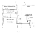
- an engine 8 such as an automotive vehicle engine, is generally shown having an injector arrangement comprising a first fuel injector 12a and a second fuel injector 12b.
- the fuel injectors 12a, 12b each have an injector valve needle 13 and a piezoelectric actuator 11.
- the piezoelectric actuator 11 is operable to cause the injector valve needle 13 to open and close to control the injection of fuel into an associated cylinder of the engine 8.
- the fuel injectors 12a, 12b may be employed in a diesel internal combustion engine to inject diesel fuel into the engine 8, or they may be employed in a spark ignited internal combustion engine to inject combustible gasoline into the engine 8.
- the fuel injectors 12a, 12b form a first injector set 10 of fuel injectors of the engine 8 and are controlled by means of a drive circuit 20a.
- the drive circuit 20a is arranged to monitor and control the injector high side voltages V 11HI , V 12HI and injector low side voltages V 11LO , V 12LO so as to control actuation of the first and second fuel injectors 12a, 12b respectively, to open and close the injectors.
- Voltages V 11HI and V 12HI represent the high side voltages of the fuel injectors 12a, 12b, respectively
- V 11LO , V 12LO represent the low side voltages of the fuel injectors 12a, 12b, respectively.
- the engine 8 may be provided with two or more injector set s, each containing one or more fuel injectors and each injector set having its own drive circuit 20a to 20 N . Where possible, for reasons of clarity, the following description relates to only one of the injector sets.
- the fuel injectors 12a, 12b are of a negative-charge displacement type. The fuel injectors 12a, 12b are therefore opened to inject fuel into the engine cylinder during a discharge phase and closed to terminate injection of fuel during a charging phase.
- the engine 8 is controlled by an Engine Control Module (ECM) 14, of which the drive circuit 20a forms an integral part.
- the ECM 14 includes a microprocessor 16 and a memory 24 which are arranged to perform various routines to control the operation of the engine 8, including the control of the fuel injector arrangement.
- the ECM 14 is arranged to monitor engine speed and load. It also controls the amount of fuel supplied to the fuel injectors 12a, 12b and the timing of operation of the fuel injectors.
- the ECM 14 is connected to an engine battery (not shown) which has battery voltage V BAT of about 12 Volts.
- the ECM 14 generates the voltages required by other components of the engine 8 from the battery voltage V BAT .
- the drive circuit 20a operates in three main phases: a charging phase, a discharge phase and a regeneration phase.
- the discharge phase the drive circuit 20a operates to discharge one of the fuel injectors 12a, 12b to open the injector valve needle 13 to inject fuel.
- the drive circuit 20a operates to charge the previously discharged fuel injector 12a, 12b to close the injector valve needle 13 to terminate injection of fuel.
- the regeneration phase energy in the form of electric charge is replenished to a first storage capacitor C 1 and a second storage capacitor C 2 (not shown in Figure 1), for use in subsequent injection cycles, so that a dedicated power supply is not required.
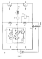
- the drive circuit 20a comprises a first voltage rail V 0 and a second voltage rail V 1 .
- the first voltage rail V 0 is at a higher voltage than the second voltage rail V 1 .
- the drive circuit 20a also includes a half-H-bridge circuit having a middle current path 32 which serves as a bi-directional current path.
- the middle current path 32 has an inductor L 1 coupled in series with the injector set 10 of fuel injectors 12a, 12b.
- the fuel injectors 12a, 12b and their associated switching circuitry are connected in parallel with each other.
- Each fuel injector 12a, 12b has the electrical characteristics of a capacitor, with its piezoelectric actuator 11 being chargeable to hold voltage which is the potential difference between a low side (-) terminal and a high side (+) terminal of the piezoelectric actuator 11.
- the drive circuit 20a further comprises the first storage capacitor C 1 and the second storage capacitor C 2 .
- Each of the storage capacitors C 1 , C 2 has a positive and a negative terminal.
- Each storage capacitor C 1 , C 2 has a high side and a low side; the high side is on the positive terminal of the capacitor and the low side is on the negative terminal.
- the first storage capacitor C 1 is connected between the first voltage rail V 0 and the second voltage rail V 1 .
- the second storage capacitor C 2 is connected between the second voltage rail V 1 and the ground potential V GND .
- the drive circuit 20a has a voltage source V s , or power supply, 22 supplied by the ECM 14, the drive circuit 20a does not have a dedicated power supply.
- the voltage source V S is connected between the second voltage rail V 1 and the ground potential V GND , and is arranged to supply energy to the second storage capacitor C 2 . Energy is supplied to the first storage capacitor C 1 by regeneration of charge to it during the regeneration phase.
- the voltage source V S is between 50 and 60 Volts.
- the drive circuit 20a there is a charge switch Q 1 and a discharge switch Q 2 for controlling, respectively, the charging and discharging operations of the first and second fuel injectors 12a, 12b.
- the charge and the discharge switches Q 1 , Q 2 are operable by the microprocessor 16.
- Each of the charge and the discharge switches Q 1 , Q 2 when closed, allows for unidirectional current flow through the respective one of the switches and, when open, prevents current flow.
- the charge switch Q 1 has a first recirculation diode RD 1 connected across it.
- the discharge switch Q 2 has a second recirculation diode RD 2 connected across it.
- recirculation diodes RD 1 , RD 2 permit recirculation current to return charge to the first storage capacitor C 1 and the second storage capacitor C 2 , respectively, during an energy recirculation phase of operation of the drive circuit 20a, in which energy is recovered from at least one of the fuel injectors 12a, 12b.
- the first fuel injector 12a is connected in series with an associated first selector switch SQ 1 and the second fuel injector 12b is connected in series with an associated second selector switch SQ 2 .
- Each of the selector switches SQ 1 , SQ 2 is operable by the microprocessor 16.
- a first diode D 1 is connected in parallel with the first selector switch SQ 1
- a second diode D 2 is connected in parallel with the second selector switch SQ 2 .
- a current I DISCHARGE is permitted to flow in a discharge direction through the selected fuel injector 12a when its associated selector switch SQ 1 is activated and the discharge switch Q2 is operated.
- the first and second diodes D 1 , D 2 each allow a current I CHARGE to flow in a charge direction during the charging phase of operation of the circuit, across the first and the second fuel injectors 12a, 12b, respectively.
- a regeneration switch circuitry is included in the drive circuit 20a in parallel with the injectors 12a, 12b to implement the regeneration phase.
- the regeneration switch circuitry serves to connect the second storage capacitor C 2 to the inductor L 1 .
- the regeneration switch circuitry comprises a regeneration switch RSQ which is operable by the microprocessor 16.
- a first regeneration switch diode RSD 1 is connected in parallel with the regeneration switch RSQ; and a second regeneration switch diode RSD 2 is coupled in series to the first regeneration switch diode RSD 1 and the regeneration switch RSQ.
- the second regeneration switch diode RSD 2 acts as a protection diode, because the first and second regeneration switch diodes RSD 1 , RSD 2 are opposed to each other, so that current will not flow through the regeneration switch circuitry unless the regeneration switch RSQ is closed and current is flowing from the second voltage rail V 1 . Current, thus, cannot pass through the regeneration switch circuitry during the charging phase.
- the middle current path 32 includes a current sensing and control means 34 that is arranged to communicate with the microprocessor 16.
- the current sensing and control means 34 is arranged to sense the current in the middle current path 32 and to compare the sensed current with a predetermined current threshold.
- the current sensing and control means 34 generates an output signal when the sensed current is substantially equal to the predetermined current threshold.
- a voltage sensing means (not shown) is also provided to sense the sensed voltage V SENSE across the fuel injector 12a, 12b selected for injection.
- the voltage sensing means is used to sense the voltages V C1 , V C2 across the first and second storage capacitors C 1 , C 2 , and the power supply 22.
- the regeneration phase is terminated when sensed voltage levels V C1 , V C2 across the first and second storage capacitors C 1 , C 2 are substantially the same as predetermined voltage levels.
- the drive circuit 20a also includes control logic 30 for receiving the output of the current sensing and control means 34, the sensed voltage, V SENSE , from the positive terminal (+) of the actuators 11 of the fuel injectors 12a and 12b, and the various output signals from the microprocessor 16 and its memory 24.
- the control logic 30 includes software executable by the microprocessor 16 for processing the various inputs so as to generate control signals for each of the charge and the discharge switches Q 1 , Q 2 , the first and second selector switches SQ 1 , SQ 2 , and the regeneration switch RSQ.
- a drive pulse (or voltage waveform) is applied to the piezoelectric actuator 11 of each fuel injector 12a and 12b, for example the first fuel injector 12a.
- the drive pulse varies between the charging voltage, V CHARGE , and the discharging voltage, V DISCHARGE .
- V CHARGE the charging voltage
- V DISCHARGE the discharging voltage
- the drive pulse is at V CHARGE so that a relatively high voltage is applied to the piezoelectric actuator 11.
- V CHARGE is around 200 to 300 V.
- the drive pulse is reduced to V DISCHARGE , which is typically around -100 V.
- the voltage of the drive pulse is increased to its charging voltage level, V CHARGE , again.
- the associated drive circuit 20a is operated in the following manner. Firstly, the discharge switch Q 2 and the first selector switch SQ 1 of the first fuel injector 12a are closed. During the discharge phase that follows, the discharge switch Q 2 is automatically opened and closed until the voltage across the selected fuel injector 12a is reduced to the appropriate voltage discharge level (i.e. V DISCHARGE ) to initiate an injection event. After a predetermined time during which injection is required, the fuel injector 12a is closed by closing the charge switch Q 1 . The closing of the charge switch Q 1 causes a charging current to flow through the first and second fuel injectors 12a and 12b.
- V DISCHARGE the appropriate voltage discharge level
- the charge switch Q 1 is continually opened and closed until the appropriate charge voltage level is achieved (i.e. V CHARGE ).
- the regeneration switch RSQ is activated, and the discharge switch Q 2 is periodically opened and closed under the control of a signal emitted by the microprocessor 16. Operation of the discharge switch Q 2 is continued until the energy on the first storage capacitor C 1 reaches a predetermined level.
- a fault of the drive circuit 20a and its associated fuel injectors 12a, 12b has detectable response characteristics that indicate the nature of the fault, for example whether it is a short circuit or an open circuit fault associated with at least one of the fuel injectors 12a, 12b.
- a fault present in the drive circuit 20a may affect the performance of the injector arrangement and may be critical, ultimately, to the performance of the engine 8.
- the aforementioned drive circuit 20a and its associated injectors 12a, 12b have already been developed, a suitable diagnostic tool and a suitable diagnostic method to detect these fault response characteristics is unknown until now.
- the drive circuit 20a of the invention is provided with an integral diagnostic tool.
- the diagnostic tool provides a robust diagnostic system that is operated according to specific diagnostic methods to detect critical failure modes of the drive circuit 20a and its associated piezoelectric fuel injectors 12a, 12b. The diagnostic tool thereby prevents complete failure of the drive circuit 20a and the fuel injectors 12a, 12b.
- the diagnostic tool includes an injector sensor circuit, a resistive bias network and a fault trip circuit.
- the injector sensor circuit comprises a first current sensor 36a and a second current sensor 36b.
- the current sensors 36a, 36b are located within the injector set 10.
- the first current sensor 36a is connected in series with the first fuel injector 12a, to the high side of the fuel injector 12a
- the second current sensor 36b is connected in series with the second fuel injector 12b, to the high side of the second fuel injector 12b. So, the first and second current sensors 36a, 36b are in parallel with each other.
- the current sensors 36a, 36b each provide an output to the microprocessor 16 of the ECM 14.
- the microprocessor 16 is arranged to operate both of the current sensors 36a, 36b and receives signals from each of the current sensors 36a, 36b indicative of current flow through the respective fuel injector 12a, 12b.
- the resistive bias network comprises a first resistor R H and a second resistor R L .
- the first resistor R H is connected between the first voltage rail V 0 and the high side of the fuel injectors 12a, 12b at a bias point P B that is connected to the inductor L 1 .
- the second resistor R L is connected to the high side of the fuel injectors 12a, 12b, at the bias point P B , and to the ground potential V GND .
- the first and second resistors R L and R H each have a known resistance of a high order of magnitude.
- a volt sensor 25 is connected across the second resistor R L and provides an output to the microprocessor 16.
- the microprocessor 16 is arranged to operate the volt sensor 25 and receives signals from the volt sensor 25 indicative of a bias voltage across the second resistor R L .
- a fault trip resistor R F is located in the connection of the drive circuit 20a to the ground potential V GND .
- a current sensor 27 is connected in series with the fault trip resistor R F in order to sense the current that passes through the fault trip resistor R F .
- the fault trip resistor R F is of very low resistance with an order of magnitude of milliohms.
- the microprocessor 16 is arranged to transmit control signals to the current sensor 27 and receives signals from the current sensor 27 indicative of the current flow through the fault trip resistor R F .
- the injector sensor circuit can detect stack terminal short circuit faults associated with the deselected fuel injector 12a, 12b and open circuit faults associated with the selected fuel injector 12a, 12b.
- the fuel injectors 12a, 12b can have other types of fault, which can be detected by using the resistive bias network and the fault trip circuit.
- the fault trip circuit detects high side and low side to ground potential short circuits
- the resistive bias network can detect all types of short circuit fault as well as open circuit faults.
- different diagnostic tools can detect the same type of fault under different circumstances. So it is advantageous to have the three diagnostic tools in the same drive circuit 20a, so that all the different types of fault can be detected, under different working conditions, which would not be possible by using one of the diagnostic tools on its own.
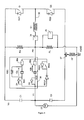
- the deselected first fuel injector 12a has a stack terminal short circuit fault.
- the first fuel injector 12a discharges through its resistive fault element R SC .
- the second selector switch SQ 2 is closed, the potential difference between the first fuel injector 12a and the second fuel injector 12b causes a current to flow (as shown by an arrow 39) from the second fuel injector 12b, through the first and second current sensors 36a, 36b, through the resistive fault element R SC and the first fuel injector 12a, through the first diode D 1 and through the second selector switch SQ 2 .
- the second fuel injector 12b discharges, the faulty first fuel injector 12a therefore recharges.
- the sensed current I sense detected by the first current sensor 36a is greater than the first threshold current I limit .
- the microprocessor 16 initiates a fault signal. If the first fuel injector 12a does not have a stack terminal short circuit (situation not shown), the sensed current I sense would be substantially equal to the first threshold current I limit . So, by monitoring the current flowing through the current sensor 36a associated with the unselected fuel injector 12a to measure I sense it is possible to determine whether or not the unselected fuel injector 12a has a stack terminal short circuit fault.
- the second injector 12a is deselected by opening the second selector switch SQ 2 and the first selector switch SQ 1 is closed to select the first fuel injector 12a. If the second current sensor 36b senses a sensed current I sense in excess of the first threshold current I limit , this is an indication that the second fuel injector 12b has a stack terminal short circuit fault and the microprocessor 16 initiates a fault signal. By selecting each fuel injector 12a, 12b in turn and by monitoring the current sensors 36a, 36b that correspond to the deselected fuel injectors of the injector set 10, it is therefore possible to determine whether or not each injector has a stack terminal short circuit fault.
- the microprocessor 16 is configured to provide a signal indicative of a fault only if the sensed current I sense exceeds the magnitude of the first threshold current I limit by a tolerance current I stol .
- the tolerance current I stol is a few milliamps.
- a fuel injector with an open circuit fault When a fuel injector with an open circuit fault is selected in conjunction with actuation of the discharge switch Q 2 (situation not shown), it does not conduct current. For example, if the selected fuel injector 12b in Figure 4 has an open circuit fault, the current sensor 36b senses an open sensed current I opsense substantially equal to the first threshold current I limit . To determine whether the selected fuel injector 12b has an open circuit fault, the current sensor 36b (that is associated with the selected fuel injector 12b) is enabled whilst the second selector switch SQ 2 and the discharge switch Q 2 are closed.
- each fuel injector 12a, 12b is selected in turn.
- each fuel injector 12a, 12b is also tested for an open circuit fault.
- the discharge switch Q 2 is actuated a short time after the testing of the unselected fuel injector 12b for stack terminal short circuit faults is complete.
- the microprocessor 16 connected to the current sensor 36b initiates a signal indicative of an open circuit fault.
- the presence of a current sensor 36a, 36b associated with each fuel injector 12a, 12b enables detection of an open circuit fault on each fuel injector 12a, 12b.
- a fuel injector 12a, 12b may conduct very small currents, even when it has an open circuit fault.
- the microprocessor 16 is therefore configured to provide a signal indicative of an open circuit fault if the sensed current I sense exceeds the magnitude of the first threshold current I limit by no more than an open circuit tolerance current I optol .
- the tolerance current is a few milliamps.
- the drive circuit 20a and its injector sensor circuit follow an operating method to detect stack terminal short circuit faults.
- the method, or diagnostic test is in the form of specific steps carried out during an injection cycle of a selected fuel injector 12a, 12b, as shown in Figure 5. Each step of the diagnostic method is carried out over a specific period of the injection cycle.
- the discharge phase of the selected injector 12a, 12b is initiated in a first period 78, by reducing the drive pulse (the voltage across the selected fuel injector 12a, 12b) to the discharge voltage level, V DISCHARGE , by operating the discharge switch Q 2 .
- An injection event of the selected fuel injector 12a, 12b occurs during a second period 79. However, the injection event is not limited to the period 79.
- the injection event starts when the valve needle 13 associated with selected fuel injector 12a, 12b opens, which is typically towards the end of the first period 78, before the selected fuel injector 12a, 12b is fully discharged.
- the injection event terminates once the valve needle 13 associated with the selected fuel injector 12a, 12b is closed. This occurs towards the beginning of a third period 70, after the start of the charge phase.
- the drive pulse is increased to the charge voltage level, V CHARGE , by operating the charge switch Q 1 .
- the injector set 10 then undergoes the regeneration phase in a fourth period 72.
- One of the fuel injectors 12a, 12b is selected before the beginning of the first period 78 and thus before the operation of the discharge switch Q 2 .
- the corresponding second selector switch SQ 2 is closed and the other fuel injector 12a is deselected by opening the corresponding first selector switch SQ 1 .
- the current sensor 36a associated with the deselected (non-injecting) fuel injector 12a is enabled to detect a stack terminal short circuit fault associated with the deselected fuel injector 12a.
- the discharge switch Q 2 is activated and the current sensor 36b associated with selected (injecting) fuel injector 12b is enabled to detect an open circuit fault.
- the current sensors 36a, 36b are disabled once the injection event of the selected injector 12b is complete, towards the beginning of the third period 70. Whichever of the fuel injectors 12a, 12b was previously deselected is then selected for injection, and vice versa.
- the injector sensor circuit monitors the current through the deselected injector 12a and the selected fuel injector 12b during the injecting sequence of the selected injector 12b. As each of the fuel injectors 12a, 12b is selected and deselected in turn through successive injection cycles, both of the fuel injectors 12a, 12b are tested for stack terminal short circuit faults and open circuit faults. Consequently, stack terminal short circuit and open circuit faults can be advantageously detected by using the injector sensor circuit in its operating method without having to add additional stages to the injection cycle.
- the selector switches SQ 1 , SQ 2 are open, the current sensors 36a, 36b are each enabled to detect an open circuit fault and the associated the fuel injectors 12a, 12b are charged by closing the charge switch Q 1 .
- Open circuit fuel injectors can be detected at this point because, on charging, current is expected flow through both fuel injectors 12a, 12b and through both of the associated current sensors 36a, 36a.
- a current sensor 36a, 36b that fails to detect current provides an indication that its associated fuel injector 12a, 12b has an open circuit fault.
- the method at start up is precisely the same as that implemented using the injector sensor circuit whilst the bank is operating under normal running conditions for detecting stack terminal short circuit faults.
- a period of time elapses before the diagnostic test for stack terminal short circuit faults is begun so as to give the unselected fuel injectors 12a, 12b time to discharge through the resistance of any stack terminal faults that might be present.
- the steps to detect open circuit faults during normal running conditions are omitted.
- the injector sensor circuit is capable of detecting stack terminal short circuit faults, it is not capable of detecting other types of short circuit fault.
- the resistive bias network as shown in Figure 3 can detect three types of short circuit fault associated with a fuel injector: a stack terminal short circuit fault, a short circuit from the low side of the actuator 11 of one the fuel injectors 12a, 12b to the ground potential V GND , and from the high side of the actuator 11 to the ground potential V GND .
- the injector sensor circuit specifically detects stack terminal faults of the actuator 11. Therefore, in using the resistive bias network and the injector sensor circuit together it is possible to detect and distinguish a high side to ground short circuit fault from a stack terminal fault. So, it is possible to detect all the different types of short circuit fault present in a fuel injector arrangement with confidence.
- the resistive bias network is dependent on the accurate prediction of the effect of a faulty injector on a bias voltage V B measured at a bias point P B .
- the magnitude of the resistance of the resistive element R SC and of the capacitance of the remaining elements of a faulty injector are unknown. It is therefore difficult to predict accurately an equivalent parallel circuit of the resistive element R SC and the remaining capacitive elements for a fuel injector, and thus the effect of such a faulty fuel injector on the measured bias voltage V BIAS .
- the injector sensor circuit is capable of detecting a stack terminal fault reliably, the injector sensor circuit provides a more robust fault detection methodology for this type of short circuit fault than the resistive bias network.
- the resistive bias network can also detect open circuit faults of a selected one of the fuel injectors 12a, 12b.
- the respective one of the selector switches SQ 1 , SQ 2 for the selected fuel injector 12a, 12b is operated.
- An open circuit fault is detected if the measured bias voltage V BIAS is not equal to substantially a predicted selected injector voltage V PinjN .
- one of the selector switches SQ 1 , SQ 2 is operated.
- the time delay exists because two readings are taken using the resistive bias network: one reading is taken without selecting one of the fuel injectors 12a, 12b, and the other reading is taken having selected one of the fuel injectors 12a, 12b.
- one of the fuel injectors 12a, 12b (for example the first fuel injector 12a) is selected by closing its associated selector switch SQ 1 .
- the measured bias voltage V BIAS then increases over a time period to a predicted selected injector voltage V PinjN .
- the predicted selected injector voltage V PinjN is equal to substantially the sum of the voltage of the second voltage rail V 1 and the voltage V injN across the selected injector 12a.
- the fuel injector 12a is deselected by opening the associated selector switch SQ 1 , and the measured bias voltage V BIAS exponentially decays over a time period to a voltage level set by the resistive bias network.
- each reading has an unavoidable error caused by the exponential decay of the measured bias voltage V BIAS selection, or deselection, one of the fuel injectors 12a, 12b.
- This error source can be minimised by allowing a short time period to elapse between taking the two readings. There is a further delay to process the readings. Therefore, making accurate measurements of the measured bias voltage V BIAS to detect open circuit and short circuit faults using the resistive bias network can be time consuming.
- the injection cycle is adapted to have an extra step, a fifth period (not shown) which occurs during the regeneration phase of the fourth period 72.
- the addition of the fifth period lengthens the duration of the injection cycle, which limits the speed of operation of the drive circuit 20a, and restricts the load range that can be applied to the engine 8.
- the fifth period is cut out of most injection cycles so that it is present periodically, e.g. in every fifth injection cycle.
- the injector sensor circuit can be used to diagnose a stack terminal fault or open circuit fault quickly. So for the injector sensor circuit, it is not necessary to alter the injection cycle to have an additional step to detect open circuit faults and stack terminal short circuit faults.
- the methods of operating the resistive bias network and the injector sensor circuit can be combined.
- the operation of these two diagnostic tools is combined in the fifth period.
- the injector arrangement is tested for short circuit faults using the resistive bias network, with the selector switches SQ 1 , SQ 2 open.
- the selector switches SQ 1 , SQ 2 is then closed to select one of the fuel injectors 12a, 12b the resistive bias network detects open circuit faults associated with the selected fuel injector 12a, 12b, and the injector sensor circuit is enabled to detect stack terminal short circuit faults associated with the deselected fuel injector.
- the injector selector switches SQ 1 , SQ 2 is closed during operation of the resistive bias network so as to detect open circuit faults, and the injector sensor circuit is operated to detect stack terminal short circuit faults.
- the fault trip circuit shown in Figure 3 is capable of detecting a short circuit fault associated with an injector arrangement, that is either a low side, or high side, short circuit fault to the ground potential V GND .
- the injector sensor circuit is able to detect a stack terminal fault, it is possible to use the fault trip circuit and the injector sensor circuit together to detect the presence of all three forms of short circuit fault in an injector arrangement at start up, and during normal operating conditions.
- the current through the fault trip resistor R F is monitored by the current sensor 27 that is operable by the microprocessor 16.
- the fault trip circuit is arranged to trip, and the microprocessor 16 is arranged to initiate a signal.
- Different switches (Q 1 , Q 2 , SQ 1 , SQ 2 , and RSQ) of the drive circuit 20a are operated to detect the two different types of short circuit to ground potential faults. As the switches are all operated (Q 1 , Q 2 , SQ 1 , SQ 2 , and RSQ) in an injection cycle the fault trip circuit is operational during normal running conditions.
- the fault trip circuit and the injector sensor circuit can be used together without adding an extra step to the injection cycle. Furthermore, by using these two diagnostic tools together, it is possible to detect short circuits and open circuits present in an injector arrangement.
- the drive circuit 20a includes the injector sensor circuit, the fault trip circuit and the resistive bias network.
- the three different diagnostic tools may be used independently to detect the different types of circuit fault. However, as can be appreciated from the aforementioned description, the three different diagnostic tools are complementary and can be used in combination to detect different types of fault under different circumstances.
- the diagnostic methods in which the injector sensor circuit is used are capable of detecting both short and open circuit faults. These methods may be used to detect these two types of fault separately, instead of together as described for the preferred embodiment.
- the injector sensor circuit may be adapted to test only for stack terminal short circuit faults or only for open circuit faults.
- the drive circuit 20a comprises only the injector sensor circuit of the three different diagnostic tools. In other embodiments, the drive circuit 20a includes the injector sensor circuit and either the resistive bias network or the fault trip circuit.
- the drive circuit 20a herein described is a generic drive circuit.
- the injector sensor circuit, the resistive bias network and fault trip circuit may each be adapted for use with similar drive circuits, for example, the drive circuits described in WO 2005/028836 .
- the drive circuit may only have one voltage rail, or it may not have the circuitry that is used in the regeneration phase.
- the drive means may have only a single charge storage means.
- the injector sensor circuit may be implemented in any drive circuit which has an injector set having at least two injectors that are all arranged in parallel, because the injector sensor circuit is integrated into the injector set 10.
- the injector set 10 may be in a drive circuit having a single charge storage means.
- the second fuel injector 12b of the injector set 10 in Figure 3 may be replaced with a capacitive component.
- This drive circuit may still allow the fault detection steps for a stack terminal short circuit fault and an open circuit fault, using the injector sensor circuit, to be used for the first fuel injector 12a, as described previously.
- the injector set 10 has only one current sensor 36a associated with the first fuel injector 12a.
- the current sensor 36a can detect an open circuit fault associated with the first fuel injector 12a when it is selected, and can detect a stack terminal short circuit fault when the first fuel injector 12a is unselected.
- the current sensor 36a can detect the presence of a stack terminal short circuit fault associated with the unselected, second fuel injector 12b.
- the described diagnostic methods may be varied so that the current sensor 36a, 36b associated with a selected fuel injector 12a, 12b is enabled to detect open circuit faults when either of the discharge switch Q 2 or the charge switch Q 1 is actuated.
- Positive charge displacement type fuel injectors may be used instead of negative charge displacement type fuel injectors.
- the piezoelectric actuators may initially be discharged by operating a discharge switch Q 2 .
- the fault trip resistor R F and the current sensor 27 can be in a single current sensing means that provides the same function.
- the diagnostic methods that test the drive circuit 20a for short circuit faults to the ground potential V GND are also capable of detecting equivalent short circuits to the voltage V BAT of the engine battery.
- each of the current sensors 36a, 36b may be connected in series: to the low side of the associated fuel injector 12a, 12b, or to the low side of the selector switch SQ 1 , SQ 2 , instead of to the high side of the associated fuel injector 12a, 12b.
- the current sensors may be connected in series between the low side of the associated fuel injector 12a, 12b and the high side of the associated selector switch SQ 1 , SQ 2 .
- a series of injection events may be performed on a single fuel injector 12a, 12b before carrying out an injection event on the other of the fuel injectors 12a, 12b.
Landscapes
- Engineering & Computer Science (AREA)
- Chemical & Material Sciences (AREA)
- Combustion & Propulsion (AREA)
- Mechanical Engineering (AREA)
- General Engineering & Computer Science (AREA)
- Electrical Control Of Air Or Fuel Supplied To Internal-Combustion Engine (AREA)
- Fuel-Injection Apparatus (AREA)
- Control Of Electric Motors In General (AREA)
- Testing, Inspecting, Measuring Of Stereoscopic Televisions And Televisions (AREA)
Priority Applications (3)
| Application Number | Priority Date | Filing Date | Title |
|---|---|---|---|
| US11/804,839 US7497204B2 (en) | 2006-05-23 | 2007-05-21 | Drive circuit for an injector arrangement and a diagnostic method |
| JP2007136142A JP4550861B2 (ja) | 2006-05-23 | 2007-05-23 | インジェクタ構成のための駆動回路及び診断方法 |
| US12/358,298 US7624721B2 (en) | 2006-05-23 | 2009-01-23 | Drive circuit for an injector arrangement and a diagnostic method |
Applications Claiming Priority (1)
| Application Number | Priority Date | Filing Date | Title |
|---|---|---|---|
| GBGB0610226.3A GB0610226D0 (en) | 2006-05-23 | 2006-05-23 | Drive circuit for an injector arrangement and a diagnostic method |
Publications (2)
| Publication Number | Publication Date |
|---|---|
| EP1860306A1 true EP1860306A1 (fr) | 2007-11-28 |
| EP1860306B1 EP1860306B1 (fr) | 2009-09-23 |
Family
ID=36687575
Family Applications (1)
| Application Number | Title | Priority Date | Filing Date |
|---|---|---|---|
| EP06253619A Not-in-force EP1860306B1 (fr) | 2006-05-23 | 2006-07-11 | Circuit pilote d'injecteur et procédé de diagnostic |
Country Status (6)
| Country | Link |
|---|---|
| US (2) | US7497204B2 (fr) |
| EP (1) | EP1860306B1 (fr) |
| JP (1) | JP4550861B2 (fr) |
| AT (1) | ATE443805T1 (fr) |
| DE (1) | DE602006009378D1 (fr) |
| GB (1) | GB0610226D0 (fr) |
Cited By (5)
| Publication number | Priority date | Publication date | Assignee | Title |
|---|---|---|---|---|
| EP2006518A1 (fr) | 2007-06-22 | 2008-12-24 | Delphi Technologies, Inc. | Détection de fautes dans un agencement d'injecteur |
| EP2058496A1 (fr) | 2007-11-09 | 2009-05-13 | Delphi Technologies, Inc. | Détection de défauts dans un ensemble d'injecteurs |
| EP2113647A2 (fr) | 2008-04-30 | 2009-11-04 | Delphi Technologies, Inc. | Détection de défauts dans un ensemble d'injecteurs piézoélectriques de carburant |
| CN106065838A (zh) * | 2015-04-21 | 2016-11-02 | 罗伯特·博世有限公司 | 用于识别在内燃机的燃料输送时的故障的方法 |
| DE102010001820B4 (de) * | 2009-02-12 | 2019-11-28 | Denso Corporation | Ansteuervorrichtung für einen Kraftstoffeinspritzer mit piezoelektrischem Aktuator |
Families Citing this family (23)
| Publication number | Priority date | Publication date | Assignee | Title |
|---|---|---|---|---|
| US8141844B2 (en) * | 2005-10-26 | 2012-03-27 | Codman NeuroSciences Sàrl | Flow rate accuracy of a fluidic delivery system |
| EP1927743A1 (fr) * | 2006-11-30 | 2008-06-04 | Delphi Technologies, Inc. | Détection de fautes dans un agencement d'injecteur |
| DE102006060311A1 (de) * | 2006-12-20 | 2008-06-26 | Robert Bosch Gmbh | Verfahren zum Betrieb eines Einspritzventils |
| DE102008001971A1 (de) * | 2008-05-26 | 2009-12-03 | Robert Bosch Gmbh | Verfahren zur Diagnose eines Lastabfalls |
| DE102008041406B4 (de) * | 2008-08-21 | 2019-07-18 | Robert Bosch Gmbh | Verfahren und Vorrichtung zur Diagnose einer Brennkraftmaschine, Computerprogramm und Computerprogrammprodukt |
| DE102008042981A1 (de) * | 2008-10-21 | 2010-04-22 | Robert Bosch Gmbh | Verfahren und Steuervorrichtung zur Ansteuerung eines Kraftstoffinjektors |
| US7918207B2 (en) * | 2009-01-02 | 2011-04-05 | Ford Global Technologies, Llc | Fuel delivery system for multi-fuel engine |
| US7856867B2 (en) * | 2009-02-06 | 2010-12-28 | Gm Global Technology Operations, Inc. | Injector control performance diagnostic systems |
| US8161946B2 (en) | 2009-11-20 | 2012-04-24 | Ford Global Technologies, Llc | Fuel injector interface and diagnostics |
| US8567369B2 (en) | 2010-11-11 | 2013-10-29 | Cameron International Corporation | Spark ignited radical injection system |
| US8844498B2 (en) * | 2010-11-11 | 2014-09-30 | Ge Oil & Gas Compression Systems, Llc | Positive displacement radical injection system |
| JP5776778B2 (ja) * | 2011-09-02 | 2015-09-09 | トヨタ自動車株式会社 | 内燃機関の燃料供給装置 |
| US20130192566A1 (en) * | 2012-01-27 | 2013-08-01 | Bahman Gozloo | Control system having configurable auxiliary power module |
| US8792222B2 (en) | 2012-02-29 | 2014-07-29 | Lg Chem, Ltd. | Driver circuit for an electric vehicle and a diagnostic method |
| US9050893B2 (en) | 2012-06-29 | 2015-06-09 | Lg Chem, Ltd. | Driver circuit for an electric vehicle and a diagnostic method for determining when a first voltage driver is shorted to a high voltage and a second voltage driver has a low electrical current flowing therethrough |
| US8861161B2 (en) | 2012-06-29 | 2014-10-14 | Lg Chem, Ltd. | Driver circuit for an electric vehicle and a diagnostic method for determining when first and second voltage drivers are shorted to a high voltage |
| US9162579B2 (en) | 2012-06-29 | 2015-10-20 | Lg Chem, Ltd. | Driver circuit for an electric vehicle and a diagnostic method for determining when a first voltage driver is shorted to a low voltage and a second voltage driver is shorted to a high voltage |
| US8994210B2 (en) | 2012-07-02 | 2015-03-31 | Lg Chem, Ltd. | Driver circuit for an electric vehicle and a diagnostic method for determining when an electrical short circuit to a ground voltage is present between a contactor coil and a voltage driver |
| US9024468B2 (en) | 2012-07-02 | 2015-05-05 | Lg Chem, Ltd. | Driver circuit for an electric vehicle and a diagnostic method for determining when a voltage driver is shorted to a ground voltage |
| EP3597899B1 (fr) * | 2013-07-29 | 2026-01-21 | Astemo, Ltd. | Dispositif d'entraînement pour dispositif d'injection de carburant et système d'injection de carburant |
| US9429126B2 (en) | 2014-06-05 | 2016-08-30 | Caterpillar Inc. | System and method for detecting short-to-ground fault |
| FR3082315B1 (fr) | 2018-06-11 | 2020-05-15 | Continental Automotive France | Procede de detection d'un dysfonctionnement d'un circuit limiteur de tension et systeme de controle pour la mise en œuvre dudit procede de detection de dysfonctionnement |
| CN115853688B (zh) * | 2022-11-25 | 2025-06-24 | 潍柴动力股份有限公司 | 喷油器卡滞诊断方法、装置和计算机可读存储介质 |
Citations (5)
| Publication number | Priority date | Publication date | Assignee | Title |
|---|---|---|---|---|
| EP1400677A2 (fr) * | 2002-09-23 | 2004-03-24 | Delphi Technologies, Inc. | Système d'injection |
| WO2004051066A1 (fr) * | 2002-12-03 | 2004-06-17 | Siemens Aktiengesellschaft | Procede de surveillance pour actionneur et circuit d'excitation correspondant |
| DE10323491A1 (de) * | 2003-05-23 | 2004-12-09 | Robert Bosch Gmbh | Verfahren zur Diagnose mindestens eines Aktors mit einem kapazitiven Element oder seiner Ansteuerung |
| WO2005028836A1 (fr) * | 2003-09-23 | 2005-03-31 | Delphi Technologies, Inc. | Circuit d'attaque pour agencement d'injecteur |
| DE102004021377A1 (de) * | 2004-04-30 | 2005-11-17 | Robert Bosch Gmbh | Verfahren zur Diagnose einer Ansteuerschaltung |
Family Cites Families (18)
| Publication number | Priority date | Publication date | Assignee | Title |
|---|---|---|---|---|
| DE1032349B (de) | 1955-12-13 | 1958-06-19 | Appbau G M B H | Kabelanschluss an Akkumulatoren-Batterien |
| DE19632871C2 (de) * | 1996-08-14 | 1998-07-02 | Siemens Ag | Vorrichtung und Verfahren zum Ansteuern wenigstens eines kapazitiven Stellgliedes |
| US6213099B1 (en) * | 1999-12-22 | 2001-04-10 | Ford Global Technologies, Inc. | System for controlling a fuel injector |
| WO2001061304A1 (fr) * | 2000-02-17 | 2001-08-23 | General Electric Company | Systeme et processus de detection de cylindres faibles dans un moteur diesel |
| DE60039676D1 (de) | 2000-04-01 | 2008-09-11 | Bosch Gmbh Robert | Vorrichtung und Verfahren zur Erkennung eines Kurzschlusses zur Batteriespannung während der Ansteuerung piezoelektrischer Elemente |
| US6360161B1 (en) * | 2000-05-04 | 2002-03-19 | Bombardier Motor Corporation Of America | Method and system for fuel injector coefficient installation |
| US6671611B1 (en) * | 2000-11-28 | 2003-12-30 | Bombardier Motor Corporation Of America | Method and apparatus for identifying parameters of an engine component for assembly and programming |
| JP4479113B2 (ja) * | 2001-02-23 | 2010-06-09 | 株式会社デンソー | ピエゾアクチュエータ駆動回路および燃料噴射装置 |
| US6761059B2 (en) * | 2002-02-05 | 2004-07-13 | International Engine Intellectual Property Company, Llc | Diagnostic tool for electric-operated fuel injectors and their drivers |
| JP3765282B2 (ja) * | 2002-04-01 | 2006-04-12 | 株式会社デンソー | ピエゾアクチュエータ駆動回路および燃料噴射装置 |
| SE522658C2 (sv) * | 2002-06-28 | 2004-02-24 | Scania Cv Abp | Metod för att identifiera ett fel förknippat med en särskild cylinder i en flercylindrig förbränningsmotor och datorprogram för genomförande av metoden |
| US6879903B2 (en) * | 2002-12-27 | 2005-04-12 | Caterpillar Inc | Method for estimating fuel injector performance |
| US7231292B2 (en) * | 2003-01-17 | 2007-06-12 | Ph2 Solutions, Inc. | Systems and methods for resetting vehicle emission system error indicators |
| US7252072B2 (en) * | 2003-03-12 | 2007-08-07 | Cummins Inc. | Methods and systems of diagnosing fuel injection system error |
| US7113862B2 (en) * | 2003-09-12 | 2006-09-26 | Brp Us Inc. | Method and system for fuel injector time delay installation |
| ITBO20030642A1 (it) * | 2003-10-31 | 2005-05-01 | Magneti Marelli Powertrain Spa | Metodo per il pilotaggio di un iniettore con verifica |
| JP4174500B2 (ja) * | 2005-07-29 | 2008-10-29 | 三菱電機株式会社 | 車両用内燃機関の制御装置 |
| EP1843027B1 (fr) * | 2006-04-03 | 2018-12-19 | Delphi International Operations Luxembourg S.à r.l. | Circuit de commande pour un arrangement d'injecteurs et méthode diagnostique |
-
2006
- 2006-05-23 GB GBGB0610226.3A patent/GB0610226D0/en not_active Ceased
- 2006-07-11 AT AT06253619T patent/ATE443805T1/de not_active IP Right Cessation
- 2006-07-11 EP EP06253619A patent/EP1860306B1/fr not_active Not-in-force
- 2006-07-11 DE DE602006009378T patent/DE602006009378D1/de active Active
-
2007
- 2007-05-21 US US11/804,839 patent/US7497204B2/en not_active Expired - Fee Related
- 2007-05-23 JP JP2007136142A patent/JP4550861B2/ja not_active Expired - Fee Related
-
2009
- 2009-01-23 US US12/358,298 patent/US7624721B2/en not_active Expired - Fee Related
Patent Citations (5)
| Publication number | Priority date | Publication date | Assignee | Title |
|---|---|---|---|---|
| EP1400677A2 (fr) * | 2002-09-23 | 2004-03-24 | Delphi Technologies, Inc. | Système d'injection |
| WO2004051066A1 (fr) * | 2002-12-03 | 2004-06-17 | Siemens Aktiengesellschaft | Procede de surveillance pour actionneur et circuit d'excitation correspondant |
| DE10323491A1 (de) * | 2003-05-23 | 2004-12-09 | Robert Bosch Gmbh | Verfahren zur Diagnose mindestens eines Aktors mit einem kapazitiven Element oder seiner Ansteuerung |
| WO2005028836A1 (fr) * | 2003-09-23 | 2005-03-31 | Delphi Technologies, Inc. | Circuit d'attaque pour agencement d'injecteur |
| DE102004021377A1 (de) * | 2004-04-30 | 2005-11-17 | Robert Bosch Gmbh | Verfahren zur Diagnose einer Ansteuerschaltung |
Cited By (7)
| Publication number | Priority date | Publication date | Assignee | Title |
|---|---|---|---|---|
| EP2006518A1 (fr) | 2007-06-22 | 2008-12-24 | Delphi Technologies, Inc. | Détection de fautes dans un agencement d'injecteur |
| EP2058496A1 (fr) | 2007-11-09 | 2009-05-13 | Delphi Technologies, Inc. | Détection de défauts dans un ensemble d'injecteurs |
| US8193816B2 (en) | 2007-11-09 | 2012-06-05 | Delphi Technologies Holding S.Arl | Detection of faults in an injector arrangement |
| EP2113647A2 (fr) | 2008-04-30 | 2009-11-04 | Delphi Technologies, Inc. | Détection de défauts dans un ensemble d'injecteurs piézoélectriques de carburant |
| DE102010001820B4 (de) * | 2009-02-12 | 2019-11-28 | Denso Corporation | Ansteuervorrichtung für einen Kraftstoffeinspritzer mit piezoelektrischem Aktuator |
| CN106065838A (zh) * | 2015-04-21 | 2016-11-02 | 罗伯特·博世有限公司 | 用于识别在内燃机的燃料输送时的故障的方法 |
| CN106065838B (zh) * | 2015-04-21 | 2021-03-05 | 罗伯特·博世有限公司 | 用于识别在内燃机的燃料输送时的故障的方法 |
Also Published As
| Publication number | Publication date |
|---|---|
| EP1860306B1 (fr) | 2009-09-23 |
| US20090133671A1 (en) | 2009-05-28 |
| US7624721B2 (en) | 2009-12-01 |
| US20080006246A1 (en) | 2008-01-10 |
| JP4550861B2 (ja) | 2010-09-22 |
| GB0610226D0 (en) | 2006-07-05 |
| US7497204B2 (en) | 2009-03-03 |
| DE602006009378D1 (de) | 2009-11-05 |
| JP2007332959A (ja) | 2007-12-27 |
| ATE443805T1 (de) | 2009-10-15 |
Similar Documents
| Publication | Publication Date | Title |
|---|---|---|
| US7497204B2 (en) | Drive circuit for an injector arrangement and a diagnostic method | |
| EP1843027B1 (fr) | Circuit de commande pour un arrangement d'injecteurs et méthode diagnostique | |
| US7822537B2 (en) | Detection of faults in an injector arrangement | |
| US7945415B2 (en) | Detection of faults in an injector arrangement | |
| US7966871B2 (en) | Detection of faults in an injector arrangement | |
| US8248074B2 (en) | Detection of faults in an injector arrangement | |
| US8193816B2 (en) | Detection of faults in an injector arrangement |
Legal Events
| Date | Code | Title | Description |
|---|---|---|---|
| PUAI | Public reference made under article 153(3) epc to a published international application that has entered the european phase |
Free format text: ORIGINAL CODE: 0009012 |
|
| 17P | Request for examination filed |
Effective date: 20070822 |
|
| AK | Designated contracting states |
Kind code of ref document: A1 Designated state(s): AT BE BG CH CY CZ DE DK EE ES FI FR GB GR HU IE IS IT LI LT LU LV MC NL PL PT RO SE SI SK TR |
|
| AX | Request for extension of the european patent |
Extension state: AL BA HR MK YU |
|
| AKX | Designation fees paid |
Designated state(s): AT BE BG CH CY CZ DE DK EE ES FI FR GB GR HU IE IS IT LI LT LU LV MC NL PL PT RO SE SI SK TR |
|
| GRAJ | Information related to disapproval of communication of intention to grant by the applicant or resumption of examination proceedings by the epo deleted |
Free format text: ORIGINAL CODE: EPIDOSDIGR1 |
|
| GRAP | Despatch of communication of intention to grant a patent |
Free format text: ORIGINAL CODE: EPIDOSNIGR1 |
|
| GRAS | Grant fee paid |
Free format text: ORIGINAL CODE: EPIDOSNIGR3 |
|
| GRAA | (expected) grant |
Free format text: ORIGINAL CODE: 0009210 |
|
| AK | Designated contracting states |
Kind code of ref document: B1 Designated state(s): AT BE BG CH CY CZ DE DK EE ES FI FR GB GR HU IE IS IT LI LT LU LV MC NL PL PT RO SE SI SK TR |
|
| REG | Reference to a national code |
Ref country code: GB Ref legal event code: FG4D |
|
| REG | Reference to a national code |
Ref country code: CH Ref legal event code: EP |
|
| REG | Reference to a national code |
Ref country code: IE Ref legal event code: FG4D |
|
| REF | Corresponds to: |
Ref document number: 602006009378 Country of ref document: DE Date of ref document: 20091105 Kind code of ref document: P |
|
| PG25 | Lapsed in a contracting state [announced via postgrant information from national office to epo] |
Ref country code: FI Free format text: LAPSE BECAUSE OF FAILURE TO SUBMIT A TRANSLATION OF THE DESCRIPTION OR TO PAY THE FEE WITHIN THE PRESCRIBED TIME-LIMIT Effective date: 20090923 Ref country code: SE Free format text: LAPSE BECAUSE OF FAILURE TO SUBMIT A TRANSLATION OF THE DESCRIPTION OR TO PAY THE FEE WITHIN THE PRESCRIBED TIME-LIMIT Effective date: 20090923 Ref country code: LT Free format text: LAPSE BECAUSE OF FAILURE TO SUBMIT A TRANSLATION OF THE DESCRIPTION OR TO PAY THE FEE WITHIN THE PRESCRIBED TIME-LIMIT Effective date: 20090923 |
|
| LTIE | Lt: invalidation of european patent or patent extension |
Effective date: 20090923 |
|
| PG25 | Lapsed in a contracting state [announced via postgrant information from national office to epo] |
Ref country code: LV Free format text: LAPSE BECAUSE OF FAILURE TO SUBMIT A TRANSLATION OF THE DESCRIPTION OR TO PAY THE FEE WITHIN THE PRESCRIBED TIME-LIMIT Effective date: 20090923 Ref country code: SI Free format text: LAPSE BECAUSE OF FAILURE TO SUBMIT A TRANSLATION OF THE DESCRIPTION OR TO PAY THE FEE WITHIN THE PRESCRIBED TIME-LIMIT Effective date: 20090923 Ref country code: PL Free format text: LAPSE BECAUSE OF FAILURE TO SUBMIT A TRANSLATION OF THE DESCRIPTION OR TO PAY THE FEE WITHIN THE PRESCRIBED TIME-LIMIT Effective date: 20090923 |
|
| NLV1 | Nl: lapsed or annulled due to failure to fulfill the requirements of art. 29p and 29m of the patents act | ||
| PG25 | Lapsed in a contracting state [announced via postgrant information from national office to epo] |
Ref country code: CY Free format text: LAPSE BECAUSE OF FAILURE TO SUBMIT A TRANSLATION OF THE DESCRIPTION OR TO PAY THE FEE WITHIN THE PRESCRIBED TIME-LIMIT Effective date: 20090923 |
|
| PG25 | Lapsed in a contracting state [announced via postgrant information from national office to epo] |
Ref country code: RO Free format text: LAPSE BECAUSE OF FAILURE TO SUBMIT A TRANSLATION OF THE DESCRIPTION OR TO PAY THE FEE WITHIN THE PRESCRIBED TIME-LIMIT Effective date: 20090923 Ref country code: PT Free format text: LAPSE BECAUSE OF FAILURE TO SUBMIT A TRANSLATION OF THE DESCRIPTION OR TO PAY THE FEE WITHIN THE PRESCRIBED TIME-LIMIT Effective date: 20100125 Ref country code: IS Free format text: LAPSE BECAUSE OF FAILURE TO SUBMIT A TRANSLATION OF THE DESCRIPTION OR TO PAY THE FEE WITHIN THE PRESCRIBED TIME-LIMIT Effective date: 20100123 Ref country code: ES Free format text: LAPSE BECAUSE OF FAILURE TO SUBMIT A TRANSLATION OF THE DESCRIPTION OR TO PAY THE FEE WITHIN THE PRESCRIBED TIME-LIMIT Effective date: 20100103 Ref country code: EE Free format text: LAPSE BECAUSE OF FAILURE TO SUBMIT A TRANSLATION OF THE DESCRIPTION OR TO PAY THE FEE WITHIN THE PRESCRIBED TIME-LIMIT Effective date: 20090923 Ref country code: CZ Free format text: LAPSE BECAUSE OF FAILURE TO SUBMIT A TRANSLATION OF THE DESCRIPTION OR TO PAY THE FEE WITHIN THE PRESCRIBED TIME-LIMIT Effective date: 20090923 |
|
| PG25 | Lapsed in a contracting state [announced via postgrant information from national office to epo] |
Ref country code: SK Free format text: LAPSE BECAUSE OF FAILURE TO SUBMIT A TRANSLATION OF THE DESCRIPTION OR TO PAY THE FEE WITHIN THE PRESCRIBED TIME-LIMIT Effective date: 20090923 |
|
| PG25 | Lapsed in a contracting state [announced via postgrant information from national office to epo] |
Ref country code: AT Free format text: LAPSE BECAUSE OF FAILURE TO SUBMIT A TRANSLATION OF THE DESCRIPTION OR TO PAY THE FEE WITHIN THE PRESCRIBED TIME-LIMIT Effective date: 20090923 Ref country code: BE Free format text: LAPSE BECAUSE OF FAILURE TO SUBMIT A TRANSLATION OF THE DESCRIPTION OR TO PAY THE FEE WITHIN THE PRESCRIBED TIME-LIMIT Effective date: 20090923 |
|
| PG25 | Lapsed in a contracting state [announced via postgrant information from national office to epo] |
Ref country code: NL Free format text: LAPSE BECAUSE OF FAILURE TO SUBMIT A TRANSLATION OF THE DESCRIPTION OR TO PAY THE FEE WITHIN THE PRESCRIBED TIME-LIMIT Effective date: 20090923 Ref country code: DK Free format text: LAPSE BECAUSE OF FAILURE TO SUBMIT A TRANSLATION OF THE DESCRIPTION OR TO PAY THE FEE WITHIN THE PRESCRIBED TIME-LIMIT Effective date: 20090923 |
|
| PLBE | No opposition filed within time limit |
Free format text: ORIGINAL CODE: 0009261 |
|
| STAA | Information on the status of an ep patent application or granted ep patent |
Free format text: STATUS: NO OPPOSITION FILED WITHIN TIME LIMIT |
|
| 26N | No opposition filed |
Effective date: 20100624 |
|
| PG25 | Lapsed in a contracting state [announced via postgrant information from national office to epo] |
Ref country code: GR Free format text: LAPSE BECAUSE OF FAILURE TO SUBMIT A TRANSLATION OF THE DESCRIPTION OR TO PAY THE FEE WITHIN THE PRESCRIBED TIME-LIMIT Effective date: 20091224 |
|
| PGFP | Annual fee paid to national office [announced via postgrant information from national office to epo] |
Ref country code: DE Payment date: 20100707 Year of fee payment: 5 |
|
| PG25 | Lapsed in a contracting state [announced via postgrant information from national office to epo] |
Ref country code: MC Free format text: LAPSE BECAUSE OF NON-PAYMENT OF DUE FEES Effective date: 20100731 |
|
| REG | Reference to a national code |
Ref country code: CH Ref legal event code: PL |
|
| GBPC | Gb: european patent ceased through non-payment of renewal fee |
Effective date: 20100711 |
|
| PG25 | Lapsed in a contracting state [announced via postgrant information from national office to epo] |
Ref country code: IT Free format text: LAPSE BECAUSE OF FAILURE TO SUBMIT A TRANSLATION OF THE DESCRIPTION OR TO PAY THE FEE WITHIN THE PRESCRIBED TIME-LIMIT Effective date: 20090923 |
|
| REG | Reference to a national code |
Ref country code: FR Ref legal event code: ST Effective date: 20110331 |
|
| PG25 | Lapsed in a contracting state [announced via postgrant information from national office to epo] |
Ref country code: CH Free format text: LAPSE BECAUSE OF NON-PAYMENT OF DUE FEES Effective date: 20100731 Ref country code: LI Free format text: LAPSE BECAUSE OF NON-PAYMENT OF DUE FEES Effective date: 20100731 |
|
| PG25 | Lapsed in a contracting state [announced via postgrant information from national office to epo] |
Ref country code: FR Free format text: LAPSE BECAUSE OF NON-PAYMENT OF DUE FEES Effective date: 20100802 |
|
| PG25 | Lapsed in a contracting state [announced via postgrant information from national office to epo] |
Ref country code: GB Free format text: LAPSE BECAUSE OF NON-PAYMENT OF DUE FEES Effective date: 20100711 Ref country code: IE Free format text: LAPSE BECAUSE OF NON-PAYMENT OF DUE FEES Effective date: 20100711 |
|
| PG25 | Lapsed in a contracting state [announced via postgrant information from national office to epo] |
Ref country code: DE Free format text: LAPSE BECAUSE OF NON-PAYMENT OF DUE FEES Effective date: 20120201 |
|
| REG | Reference to a national code |
Ref country code: DE Ref legal event code: R119 Ref document number: 602006009378 Country of ref document: DE Effective date: 20120201 |
|
| PG25 | Lapsed in a contracting state [announced via postgrant information from national office to epo] |
Ref country code: LU Free format text: LAPSE BECAUSE OF NON-PAYMENT OF DUE FEES Effective date: 20100711 Ref country code: BG Free format text: LAPSE BECAUSE OF FAILURE TO SUBMIT A TRANSLATION OF THE DESCRIPTION OR TO PAY THE FEE WITHIN THE PRESCRIBED TIME-LIMIT Effective date: 20090923 Ref country code: HU Free format text: LAPSE BECAUSE OF FAILURE TO SUBMIT A TRANSLATION OF THE DESCRIPTION OR TO PAY THE FEE WITHIN THE PRESCRIBED TIME-LIMIT Effective date: 20100324 |
|
| PG25 | Lapsed in a contracting state [announced via postgrant information from national office to epo] |
Ref country code: TR Free format text: LAPSE BECAUSE OF FAILURE TO SUBMIT A TRANSLATION OF THE DESCRIPTION OR TO PAY THE FEE WITHIN THE PRESCRIBED TIME-LIMIT Effective date: 20090923 |