EP1860352A2 - Mehrganggetriebe mit Brennstoffsparmodus - Google Patents
Mehrganggetriebe mit Brennstoffsparmodus Download PDFInfo
- Publication number
- EP1860352A2 EP1860352A2 EP07106886A EP07106886A EP1860352A2 EP 1860352 A2 EP1860352 A2 EP 1860352A2 EP 07106886 A EP07106886 A EP 07106886A EP 07106886 A EP07106886 A EP 07106886A EP 1860352 A2 EP1860352 A2 EP 1860352A2
- Authority
- EP
- European Patent Office
- Prior art keywords
- engine
- transmission
- operating
- multiple speed
- speed
- Prior art date
- Legal status (The legal status is an assumption and is not a legal conclusion. Google has not performed a legal analysis and makes no representation as to the accuracy of the status listed.)
- Withdrawn
Links
- 239000000446 fuel Substances 0.000 title claims abstract description 101
- 230000005540 biological transmission Effects 0.000 title claims abstract description 87
- 238000000034 method Methods 0.000 claims abstract description 36
- 230000009347 mechanical transmission Effects 0.000 claims abstract description 26
- 238000002485 combustion reaction Methods 0.000 claims description 10
- 238000013500 data storage Methods 0.000 claims description 3
- 238000011017 operating method Methods 0.000 claims 7
- 230000006870 function Effects 0.000 description 4
- 230000000712 assembly Effects 0.000 description 2
- 238000000429 assembly Methods 0.000 description 2
- 230000003190 augmentative effect Effects 0.000 description 2
- 238000004590 computer program Methods 0.000 description 2
- 238000010586 diagram Methods 0.000 description 2
- 238000007689 inspection Methods 0.000 description 2
- 230000009467 reduction Effects 0.000 description 2
- IYLGZMTXKJYONK-ACLXAEORSA-N (12s,15r)-15-hydroxy-11,16-dioxo-15,20-dihydrosenecionan-12-yl acetate Chemical compound O1C(=O)[C@](CC)(O)C[C@@H](C)[C@](C)(OC(C)=O)C(=O)OCC2=CCN3[C@H]2[C@H]1CC3 IYLGZMTXKJYONK-ACLXAEORSA-N 0.000 description 1
- 230000008859 change Effects 0.000 description 1
- 239000000567 combustion gas Substances 0.000 description 1
- 230000009977 dual effect Effects 0.000 description 1
- 239000007789 gas Substances 0.000 description 1
- 230000001788 irregular Effects 0.000 description 1
- 230000004048 modification Effects 0.000 description 1
- 238000012986 modification Methods 0.000 description 1
- 238000005457 optimization Methods 0.000 description 1
- IYLGZMTXKJYONK-UHFFFAOYSA-N ruwenine Natural products O1C(=O)C(CC)(O)CC(C)C(C)(OC(C)=O)C(=O)OCC2=CCN3C2C1CC3 IYLGZMTXKJYONK-UHFFFAOYSA-N 0.000 description 1
- 230000003068 static effect Effects 0.000 description 1
- 230000000007 visual effect Effects 0.000 description 1
Images


Classifications
-
- F—MECHANICAL ENGINEERING; LIGHTING; HEATING; WEAPONS; BLASTING
- F16—ENGINEERING ELEMENTS AND UNITS; GENERAL MEASURES FOR PRODUCING AND MAINTAINING EFFECTIVE FUNCTIONING OF MACHINES OR INSTALLATIONS; THERMAL INSULATION IN GENERAL
- F16H—GEARING
- F16H61/00—Control functions within control units of change-speed- or reversing-gearings for conveying rotary motion ; Control of exclusively fluid gearing, friction gearing, gearings with endless flexible members or other particular types of gearing
- F16H61/02—Control functions within control units of change-speed- or reversing-gearings for conveying rotary motion ; Control of exclusively fluid gearing, friction gearing, gearings with endless flexible members or other particular types of gearing characterised by the signals used
- F16H61/0202—Control functions within control units of change-speed- or reversing-gearings for conveying rotary motion ; Control of exclusively fluid gearing, friction gearing, gearings with endless flexible members or other particular types of gearing characterised by the signals used the signals being electric
- F16H61/0204—Control functions within control units of change-speed- or reversing-gearings for conveying rotary motion ; Control of exclusively fluid gearing, friction gearing, gearings with endless flexible members or other particular types of gearing characterised by the signals used the signals being electric for gearshift control, e.g. control functions for performing shifting or generation of shift signal
- F16H61/0213—Control functions within control units of change-speed- or reversing-gearings for conveying rotary motion ; Control of exclusively fluid gearing, friction gearing, gearings with endless flexible members or other particular types of gearing characterised by the signals used the signals being electric for gearshift control, e.g. control functions for performing shifting or generation of shift signal characterised by the method for generating shift signals
-
- B—PERFORMING OPERATIONS; TRANSPORTING
- B60—VEHICLES IN GENERAL
- B60W—CONJOINT CONTROL OF VEHICLE SUB-UNITS OF DIFFERENT TYPE OR DIFFERENT FUNCTION; CONTROL SYSTEMS SPECIALLY ADAPTED FOR HYBRID VEHICLES; ROAD VEHICLE DRIVE CONTROL SYSTEMS FOR PURPOSES NOT RELATED TO THE CONTROL OF A PARTICULAR SUB-UNIT
- B60W30/00—Purposes of road vehicle drive control systems not related to the control of a particular sub-unit, e.g. of systems using conjoint control of vehicle sub-units
- B60W30/18—Propelling the vehicle
- B60W30/188—Controlling power parameters of the driveline, e.g. determining the required power
- B60W30/1882—Controlling power parameters of the driveline, e.g. determining the required power characterised by the working point of the engine, e.g. by using engine output chart
-
- B—PERFORMING OPERATIONS; TRANSPORTING
- B60—VEHICLES IN GENERAL
- B60W—CONJOINT CONTROL OF VEHICLE SUB-UNITS OF DIFFERENT TYPE OR DIFFERENT FUNCTION; CONTROL SYSTEMS SPECIALLY ADAPTED FOR HYBRID VEHICLES; ROAD VEHICLE DRIVE CONTROL SYSTEMS FOR PURPOSES NOT RELATED TO THE CONTROL OF A PARTICULAR SUB-UNIT
- B60W10/00—Conjoint control of vehicle sub-units of different type or different function
- B60W10/10—Conjoint control of vehicle sub-units of different type or different function including control of change-speed gearings
- B60W10/11—Stepped gearings
-
- F—MECHANICAL ENGINEERING; LIGHTING; HEATING; WEAPONS; BLASTING
- F16—ENGINEERING ELEMENTS AND UNITS; GENERAL MEASURES FOR PRODUCING AND MAINTAINING EFFECTIVE FUNCTIONING OF MACHINES OR INSTALLATIONS; THERMAL INSULATION IN GENERAL
- F16H—GEARING
- F16H61/00—Control functions within control units of change-speed- or reversing-gearings for conveying rotary motion ; Control of exclusively fluid gearing, friction gearing, gearings with endless flexible members or other particular types of gearing
- F16H2061/0015—Transmission control for optimising fuel consumptions
-
- F—MECHANICAL ENGINEERING; LIGHTING; HEATING; WEAPONS; BLASTING
- F16—ENGINEERING ELEMENTS AND UNITS; GENERAL MEASURES FOR PRODUCING AND MAINTAINING EFFECTIVE FUNCTIONING OF MACHINES OR INSTALLATIONS; THERMAL INSULATION IN GENERAL
- F16H—GEARING
- F16H2300/00—Determining of new ratio
- F16H2300/14—Selecting a state of operation, e.g. depending on two wheel or four wheel drive mode
-
- F—MECHANICAL ENGINEERING; LIGHTING; HEATING; WEAPONS; BLASTING
- F16—ENGINEERING ELEMENTS AND UNITS; GENERAL MEASURES FOR PRODUCING AND MAINTAINING EFFECTIVE FUNCTIONING OF MACHINES OR INSTALLATIONS; THERMAL INSULATION IN GENERAL
- F16H—GEARING
- F16H63/00—Control outputs from the control unit to change-speed- or reversing-gearings for conveying rotary motion or to other devices than the final output mechanism
- F16H63/40—Control outputs from the control unit to change-speed- or reversing-gearings for conveying rotary motion or to other devices than the final output mechanism comprising signals other than signals for actuating the final output mechanisms
- F16H63/42—Ratio indicator devices
-
- Y—GENERAL TAGGING OF NEW TECHNOLOGICAL DEVELOPMENTS; GENERAL TAGGING OF CROSS-SECTIONAL TECHNOLOGIES SPANNING OVER SEVERAL SECTIONS OF THE IPC; TECHNICAL SUBJECTS COVERED BY FORMER USPC CROSS-REFERENCE ART COLLECTIONS [XRACs] AND DIGESTS
- Y02—TECHNOLOGIES OR APPLICATIONS FOR MITIGATION OR ADAPTATION AGAINST CLIMATE CHANGE
- Y02T—CLIMATE CHANGE MITIGATION TECHNOLOGIES RELATED TO TRANSPORTATION
- Y02T10/00—Road transport of goods or passengers
- Y02T10/10—Internal combustion engine [ICE] based vehicles
- Y02T10/40—Engine management systems
-
- Y—GENERAL TAGGING OF NEW TECHNOLOGICAL DEVELOPMENTS; GENERAL TAGGING OF CROSS-SECTIONAL TECHNOLOGIES SPANNING OVER SEVERAL SECTIONS OF THE IPC; TECHNICAL SUBJECTS COVERED BY FORMER USPC CROSS-REFERENCE ART COLLECTIONS [XRACs] AND DIGESTS
- Y02—TECHNOLOGIES OR APPLICATIONS FOR MITIGATION OR ADAPTATION AGAINST CLIMATE CHANGE
- Y02T—CLIMATE CHANGE MITIGATION TECHNOLOGIES RELATED TO TRANSPORTATION
- Y02T10/00—Road transport of goods or passengers
- Y02T10/80—Technologies aiming to reduce greenhouse gasses emissions common to all road transportation technologies
- Y02T10/84—Data processing systems or methods, management, administration
Definitions
- the invention relates generally to a method of efficiently operating a multiple speed transmission and engine combination and more specifically to a method of operating a multiple speed mechanical or automated mechanical transmission and engine combination which utilizes the fuel map of the particular type or brand of engine to optimize fuel consumption of the engine/transmission combination.
- a relatively conventional multiple speed (gear ratio) heavy duty transmission includes an actuator assembly which is controlled by a master controller or microprocessor.
- the microprocessor includes a plurality of inputs which receive signals from various sensors such as speed sensors, a throttle position sensor, brake and ABS sensors, a shift selector, an operator controlled mode selector and other devices and, through the use of algorithms, computational routines, look-up tables and the like, controls operation of the master clutch and selection and engagement of transmission gears. Because such systems will consistently command upshifts and downshifts based upon the sensed conditions and established shift rules, fuel efficiency of such devices is generally good.
- the fuel efficiency (consumption) of a particular engine may be presented in a fuel efficiency map.
- This map relates fuel consumption as a function of engine speed, delivered torque and delivered horsepower.
- the fuel map includes a plurality of isograms or isolines of constant fuel consumption which are roughly arranged about a single value of speed and torque, i.e., a point, of maximum fuel efficiency.
- a single, vehicle operator or a single shift program when used with two engines having distinct fuel efficiency maps will be unable to achieve optimum fuel efficiency with both and may perform at a fuel efficiency well below that which could be obtained by commanding shifts based upon the fuel efficiency map of the given engine to achieve optimum fuel efficiency.
- the fully automatic mode may include several sub-modes that emphasize, that is, more heavily weight, one control variable or parameter over others. For example, one automatic control mode may emphasize performance, while another may provide improved control at very low vehicle speeds while a third may seek to minimize shifting by utilizing more widely separated upshift and downshift values.
- the present invention is directed to further improving the fuel efficiency of multiple speed mechanical and automated mechanical transmission engine combinations.
- An method of operating a multiple speed mechanical transmission and engine combination to optimize (reduce) fuel consumption comprises the steps of determining a fuel efficiency map for an engine, providing a multiple speed transmission controller having program and data storage capabilities, providing and storing data regarding the fuel efficiency map in the controller and a providing a control algorithm in said controller whereby operation of the engine/transmission combination is optimized for fuel economy in accordance with the fuel efficiency map.
- AMT automated mechanical transmission
- Figure 1 is a diagrammatic, plan view of a motor vehicle driveline utilizing an automated mechanical transmission and controller incorporating the present invention
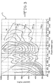
- Figure 2 is a typical or representative fuel efficiency map of a first particular type or brand of internal combustion engine
- Figure 3 is a typical or representative fuel efficiency map of a second particular type or brand of internal combustion engine
- FIG. 4 is a block diagram of a computer program for use with an automated mechanical transmission which embodies the present invention.
- FIG. 5 is a block diagram of a computer program for use with a conventional mechanical transmission which embodies the present invention.
- FIG. 1 a diagrammatic, plan view of a typical truck tractor incorporating the present invention is illustrated and generally designated by the reference number 10.
- the truck tractor 10 -includes a prime mover 12 which may be an internal combustion gas or Diesel engine having an output provided directly to a master friction clutch 14.
- the master friction clutch 14 selectively and positively engages the output of the prime mover 12 to an input of a multiple speed, gear change transmission 16.
- the transmission 16 is preferably of the type currently designated as an automated mechanical transmission (AMT) wherein gear or speed ratio changes of a splitter, a main transmission, and a planetary gear assembly, for example, are all achieved by an automated, i.e., electric, hydraulic or pneumatic, shift actuator assembly 18A connected through a data or control link 19 to a master microprocessor or controller 20.
- AMT automated mechanical transmission
- the transmission 16 may be a conventional operator (manually) shifted multiple speed ratio transmission having a gear shift lever (not illustrated) extending into the cab of the truck tractor 10.
- the master microprocessor or controller 20 includes data input ports, memory, one or more processors and data and control outputs driving, for example, the shift actuator assembly 18A or a visual or audible indicator 18B.
- the master microprocessor or controller 20 is preferably coupled by a data and control link 21 to an engine controller 22.
- the engine controller 22 is an integral component of the prime mover 12 and will typically include a processor or controller which receives data from an engine speed sensor and other sensors or devices and controls (not illustrated), for example, a fuel control or metering device capable of adjusting and terminating the flow of fuel to the prime mover 12 and thus its speed.
- the master friction clutch 14 also includes a master friction clutch operator assembly 24 which controls the engagement and disengagement of the master friction clutch 14.
- the manual transmission 16 may be paired with a manual, i.e. vehicle operator actuator friction clutch.
- a throttle position sensor 26 senses the position of a vehicle throttle or accelerator pedal 28 and provides real time data regarding the position of the throttle pedal 28 to the master controller 20, which, in turn, typically will provide such data to the engine controller 22.
- the output of the transmission 16 is provided to a rear driveline assembly 30 which includes a rear propshaft 32 which drives a conventional rear differential 34.
- the rear differential 34 provides drive torque to a pair of rear axles 36 which are in turn coupled to left and right rear tire and wheel assemblies 38 which may be either a dual configuration illustrated or a single left and right tire and wheel assembly.
- Suitable universal joints 42 may be utilized as necessary with the rear propshaft 32 to accommodate static and dynamic offsets and misalignments thereof.
- an operator adjustable gear selector lever or assembly 44 having an output which is provided to the master controller 20.
- the gear selector lever assembly 44 defines a shift pattern 46 through which the vehicle operator may select, for example, whether the master controller 20 will automatically select and shift between available gears of the transmission 16 or defeat or override such automatic selection and manually select and engage a desired gear.
- One or more push buttons or toggle switches 48 may be utilized to receive commands from the operator to select or de-select an operating mode or condition such as the fuel economy mode of the present invention.
- a stationary front axle 50 pivotally supports a pair of front tire and wheel assemblies 52 which are controllably pivoted by a steering linkage 54 which is coupled to and positioned by a steering wheel 56.
- Figures 2 and 3 present two fuel (efficiency) maps 60 and 70 which set forth the fuel consumption (efficiency) of two different brands, types or models of internal combustion truck engines as a function of engine speed and engine torque output.
- Engine speed in revolutions per minute (RPM) is presented along the X axis of Figures 2and 3 and engine torque output (lb.ft) is presented along the Y axis of Figures 2 and 3.
- Curved dashed lines superimposed on the isograms of the graphs represent various levels of horsepower output of an engine or prime mover 12.
- the irregular lines or curves of the graph are isograms (isolines) of constant fuel consumption.
- the fuel maps 60 and 70 may also be viewed as three dimensional, i.e., topologic, maps with surfaces sloping down and away from a point (peak) disposed with a closed, oblong region or isogram 62.
- the fuel map 60 represents the operational characteristics of a first, particular engine or prime mover 12. It should be understood, however, that the fuel map 60 is presented by way of example and illustration only.
- the closed, oblong region or isogram 62 generally disposed in the middle of the fuel map 60 represents a region of substantially optimum, i.e., maximum, fuel efficiency or minimum fuel consumption relative to maximum energy output. The condition of optimum fuel efficiency is, as noted, a point within the region 62.
- Each isogram or isoline 64 more distant from this closed, oblong isogram 62 represents operating conditions having increased but constant fuel efficiency. All of the isograms or isolines 62 and 64 represent varying operating conditions of engine speed and load having constant fuel efficiency or consumption measured, for example, by brake specific fuel consumption (BSFC).
- BSFC brake specific fuel consumption
- a fuel (efficiency) map 70 for a second, distinct brand, type or model of internal combustion engine or prime mover 12 is illustrated.
- the oblong region or isogram 72 likewise represents a region of substantially optimum fuel efficiency.
- the best fuel efficiency is represented by a point within the isogram 72.
- the surrounding isograms or isolines 74 represent lines of constant fuel efficiency; the farther away from the isogram 72, the poorer the fuel efficiency.
- the present invention utilizes the data contained in the fuel map of a particular engine or prime mover 12 which may be stored in the master controller 20 to influence the shift program of the master controller 20. Specifically, when an economy mode has been engaged, operation of the prime mover 12 and the transmission 16, are adjusted within limits, to operate within, or as near as possible to, the closed, oblong isograms 62 and 72 representing that operation providing the best fuel economy associated with a specific manufacturer, design or type of engine or prime mover 12.
- the first aspect of the invention is to read and store the fuel map data 60 or 70, for example, for a particular manufacturer and design or type of engine or prime mover 12 such as a Diesel engine within the memory of the master microprocessor controller 20.
- the data designating the closed, oblong region or isogram 62 such as the engine speed and engine load, and horsepower if desired, as discussed above, is the most critical with corresponding data more distant the closed, oblong isogram 62 of increasingly less significance. That is, data regarding the isogram 64 most removed from the closed, oblong isogram 62 is of negligible importance whereas those isograms 64 more proximate the closed, oblong isogram 62 are more important.
- engine speed is the controllable variable whereas engine load is a function of primarily the speed of the vehicle and the currently selected operating gear ratio.
- engine speed may be between 1400 and 1500 rpm
- engine efficiency may be significantly below that enjoyed when the engine is operating at a design load and horsepower, for example, 1000 pound feet and 300 horsepower.
- a prime mover 12 such as a gas or Diesel engine in an economy mode is most significant in the higher number (lower actual numerical) gear ratios.
- an economy mode program or subroutine 80 may be executed.
- the program 80 starts with an initialization step 82 and moves to a first decision point 84 which determines whether an operator manipulatable switch or push button 48 or a certain motion of the gear selector lever assembly 44 has established that the driver wishes to engage the economy mode of the transmission 16. If the economy mode of the transmission 16 has not been activated, the decision point 84 exits at NO and the program 80 terminates at an end point 86.
- the decision point 84 is exited at YES and a second decision point 90 is entered which inquires whether the transmission 16 is in its highest number (lowest numerical ratio) gear. If it is not, the program 80 moves to a third decision point 92 which inquires whether the transmission assembly 16 is in its next highest gear. If it is not, the third decision point 92 is exited at NO and a process step 94 is entered which activates and counts down a short duration timer.
- the timer may define a delay of typically between two and ten seconds or more or less depending upon the dynamic performance of the vehicle, the specific type of the vehicle and other operating and mechanical parameters.
- the program 80 returns to the input of the decision point 90. If the transmission is in the highest gear, the decision point 90 is exited at YES and a fourth decision point 96 next inquires whether the speed of the engine or prime mover 12 is less than, for example 1150 rpm. If it is not, the decision point is exited at NO and the program 80 terminates at the end point 86. If the speed of the engine or prime mover 12 is less than 1250 rpm, a process step 98 is entered which commands a downshift to increase the speed of the engine or prime mover 12 and move it closer to the maximum efficiency closed isogram 62. Again, the program 80 terminates at the end point 86.
- the decision point 92 if the transmission 16 is in the next to the highest gear, the decision point 92 is exited at YES and a decision point 102 is entered which inquires whether the speed of the engine or prime mover 12 is greater than 1650 rpm. If it is, the decision point 102 is exited at YES and the program 80 enters a process step 104 which commands an upshift of the transmission assembly 16 to the highest gear in order to slow the speed of the engine or prime mover 12 and move the operating point to the left in Figure 2, closer to the isogram 62.
- the decision point 102 if the speed of the engine or primer mover 12 is not greater than 1650 rpm, the decision point 102 is exited at NO and the program 80 enters a decision point 106 which inquires whether the speed of the engine or prime mover 12 is less than 1150 rpm. If it is not, the decision point 106 is exited at NO and the program concludes at the end point 86.
- the decision point 106 is exited at YES and the program 80 enters a process step 108 which commands a downshift of the transmission 16 to increase the rpm of the engine or prime mover 12 and move the operating point to the right, more proximate the isogram 62.
- the foregoing economy mode program 80 has discussed operation only in the highest two gears (lowest numerical ratios) of the transmission 16. It should be appreciated that certain vehicles, performance and service requirements may encourage or necessitate operation in the economy or fuel efficiency mode of the present invention in lower gears, for example, ninth and tenth gears of a twelve speed transmission. To enable such operation in, for example, the four highest gears, the decision points 90 and 92 must be augmented or modified to inquire regarding additional gear ratios or selections.
- a manual transmission economy mode program or subroutine 110 may be selected and executed.
- the program 110 starts with an initialization step 112 and moves to a decision point 114 which determines whether an operator controlled switch or push button 48 has been activated to indicate that the vehicle operator wishes to drive or operate in the economy mode. If the economy mode has not been selected, the first decision point 114 exits at NO and the program 110 terminates at an end point 116.
- the decision point 114 is exited at YES and a second decision point 120 is entered which inquires whether the transmission 16 is in its highest number (lowest numerical ratio) gear. If it is not, the program 110 moves to a third decision point 122 which inquires whether the transmission 16 is in its next highest gear. If it is not, the third decision point 122 is exited at NO and a process step 124 is entered which activates and counts down a short duration timer.
- the timer of the process step 124 may define a delay of typically between two and ten seconds or more or less depending upon the dynamic performance of the vehicle, the specific type of the vehicle and other operating and mechanical parameters.
- the program 110 returns to the input of the second decision point 120. If the transmission is in the highest gear, the second decision point 120 is exited at YES and a fourth decision point 126 next inquires whether the speed of the engine or prime mover 12 is less than, for example, 1200 rpm. If it is not, the fourth decision point 126 is exited at NO and the program 110 terminates at the end point 116.
- a process step 128 is entered which illuminates an indicator light, or provides another graphic, audible or tactile signal to the vehicle operator to downshift the transmission 16 to increase the speed of the engine or prime mover 12 and move such speed closer to the maximum efficiency closed isogram 62.
- the program 110 terminates at the end point 116.
- the decision point 122 is exited at YES and a fifth decision point 132 is entered which inquires whether the speed of the engine or prime mover 12 is greater than 1600 rpm. If it is, the decision point 132 is exited at YES and the program 110 enters a process step 134 which illuminates an indicator light or provides another graphic, audible or tactile signal to the vehicle operator to upshift the transmission 16 to the highest gear in order to slow the speed of the engine or prime mover 12 and move the operating point to the left in Figure 2, closer to the isogram 62.
- the decision point 132 if the speed of the engine or primer mover 12 is not greater than 1600 rpm, the decision point 132 is exited at NO and the program 110 enters a sixth decision point 136 which inquires whether the speed of the engine or prime mover 12 is less than 1200 rpm. If it is not, the decision point 136 is exited at NO and the program 1110 concludes at the end point 116.
- the fifth decision point 136 is exited at YES and the program 110 enters a process step 138 which illuminates an indicator light or provides other graphic, audible or tactile signal to the vehicle operator to downshift the transmission 16 to increase the rpm of the engine or prime mover 12 and move the operating point to the right, more proximate the isogram 62.
Landscapes
- Engineering & Computer Science (AREA)
- General Engineering & Computer Science (AREA)
- Mechanical Engineering (AREA)
- Automation & Control Theory (AREA)
- Transportation (AREA)
- Control Of Transmission Device (AREA)
- Control Of Vehicle Engines Or Engines For Specific Uses (AREA)
Applications Claiming Priority (1)
| Application Number | Priority Date | Filing Date | Title |
|---|---|---|---|
| US11/439,032 US7684919B2 (en) | 2006-05-23 | 2006-05-23 | Multiple speed transmission having fuel economy mode |
Publications (2)
| Publication Number | Publication Date |
|---|---|
| EP1860352A2 true EP1860352A2 (de) | 2007-11-28 |
| EP1860352A3 EP1860352A3 (de) | 2011-11-30 |
Family
ID=38430552
Family Applications (1)
| Application Number | Title | Priority Date | Filing Date |
|---|---|---|---|
| EP07106886A Withdrawn EP1860352A3 (de) | 2006-05-23 | 2007-04-25 | Mehrganggetriebe mit Brennstoffsparmodus |
Country Status (2)
| Country | Link |
|---|---|
| US (1) | US7684919B2 (de) |
| EP (1) | EP1860352A3 (de) |
Cited By (1)
| Publication number | Priority date | Publication date | Assignee | Title |
|---|---|---|---|---|
| US8751118B2 (en) | 2009-12-17 | 2014-06-10 | Scania Cv Ab | Method and system for driving of a vehicle |
Families Citing this family (18)
| Publication number | Priority date | Publication date | Assignee | Title |
|---|---|---|---|---|
| EP1925520A1 (de) * | 2006-11-24 | 2008-05-28 | Caterpillar, Inc. | Verfahren zur Steuerung eines Antriebsstrangs und entsprechender Antriebsstrang |
| FR2911657B1 (fr) * | 2007-01-24 | 2009-02-20 | Renault Sas | Procede et dispositif d'aide a la conduite d'un vehicule. |
| WO2009054757A1 (en) * | 2007-10-26 | 2009-04-30 | Volvo Lastvagnar Ab | A method for a more efficient use of a combustion engine in a vehicle |
| DE102010063582A1 (de) * | 2010-12-20 | 2012-06-21 | Zf Friedrichshafen Ag | Vorrichtung für einen Antriebsstrang eines Hybridfahrzeugs, Antriebsstrang und Verfahren zum Betreiben derselben |
| EP2696112B1 (de) * | 2011-11-09 | 2020-05-20 | Toyota Jidosha Kabushiki Kaisha | Gangschaltungsanzeigevorrichtung |
| US9383000B2 (en) * | 2011-11-11 | 2016-07-05 | Volkswagen Ag | Gearshift knob and method for operating a vehicle |
| US8862346B2 (en) | 2012-03-20 | 2014-10-14 | Eaton Corporation | System and method for simulating the performance of a virtual vehicle |
| EP2934977B1 (de) | 2012-12-20 | 2019-06-12 | CNH America LLC | System und verfahren zur reduzierung des kraftstoffverbrauchs eines arbeitsfahrzeugs |
| US9037367B2 (en) * | 2013-06-27 | 2015-05-19 | Toyota Motor Engineering & Manufacturing North America, Inc. | System and method for inhibiting top gear at winding road driving |
| CN103499926B (zh) * | 2013-10-21 | 2015-12-23 | 重庆青山工业有限责任公司 | Amt变速箱离合器仿真台及离合器分离与接合的仿真方法 |
| US9188223B1 (en) * | 2014-08-29 | 2015-11-17 | Ford Global Technologies, Llc | Haptic feedback shift indicator |
| WO2017095426A1 (en) | 2015-12-03 | 2017-06-08 | Allison Transmission, Inc. | System and method to control the operation of a transmission using engine fuel consumption data |
| US20170174219A1 (en) * | 2015-12-18 | 2017-06-22 | Cnh Industrial America Llc | Auto-efficiency mode for power shift transmissions |
| US10189468B2 (en) * | 2016-02-26 | 2019-01-29 | Ford Global Technologies, Llc | Paddle shifter control of hybrid powertrain |
| WO2017221233A1 (en) * | 2016-06-19 | 2017-12-28 | Joshua Waldhorn | System and method for optimized cruise control |
| JP6589894B2 (ja) * | 2017-01-18 | 2019-10-16 | トヨタ自動車株式会社 | 車両の制御装置 |
| CN109910890B (zh) * | 2019-03-19 | 2020-11-27 | 吉林大学 | 一种基于道路地形信息的卡车预测节能系统及控制方法 |
| WO2021077182A1 (en) | 2019-10-24 | 2021-04-29 | Volvo Truck Corporation | System and method for controlling engine fueling and vehicle including such a system |
Family Cites Families (20)
| Publication number | Priority date | Publication date | Assignee | Title |
|---|---|---|---|---|
| JPS6026731B2 (ja) * | 1978-08-30 | 1985-06-25 | トヨタ自動車株式会社 | 車輌用変速機の変速時期指令装置 |
| JPS5531669A (en) * | 1978-08-30 | 1980-03-06 | Toyota Motor Corp | Speed change timing instructor for vehicle speed change gear |
| US4463629A (en) | 1979-11-05 | 1984-08-07 | S. Himmelstein And Company | Energy efficient drive system |
| DE3101056A1 (de) * | 1981-01-15 | 1982-08-05 | Daimler-Benz Ag, 7000 Stuttgart | Verfahren und einrichtung zur ermittlung von schaltsignalen |
| JPS58160818A (ja) * | 1982-03-18 | 1983-09-24 | Toyota Motor Corp | 変速操作指示装置 |
| JPS59127087A (ja) * | 1983-01-12 | 1984-07-21 | トヨタ自動車株式会社 | 変速操作指示方法 |
| DE3311306A1 (de) * | 1983-03-28 | 1984-10-11 | Wabco Westinghouse Fahrzeugbremsen GmbH, 3000 Hannover | Kontrolleinrichtung fuer ein fahrzeug-getriebe zur feststellung des wirtschaftlichen fahrbereichs |
| EP0393040B1 (de) * | 1987-08-17 | 1991-11-06 | ZF FRIEDRICHSHAFEN Aktiengesellschaft | Steuereinrictung zum selbsttätigen schalten von stufenwechselgetrieben |
| JPH0463923A (ja) * | 1990-06-30 | 1992-02-28 | Mazda Motor Corp | エンジン及び自動変速機の制御装置 |
| US5458545A (en) | 1994-01-21 | 1995-10-17 | Chrysler Corporation | Adaptive line pressure control for an electronic automatic transmission |
| US5795264A (en) * | 1997-02-05 | 1998-08-18 | Eaton Corporation | Sensing manual shift into automated upper ratios |
| DE19757328A1 (de) | 1997-12-23 | 1999-06-24 | Bosch Gmbh Robert | System zur Einstellung einer Getriebeübersetzung |
| US6436005B1 (en) * | 1998-06-18 | 2002-08-20 | Cummins, Inc. | System for controlling drivetrain components to achieve fuel efficiency goals |
| US6616575B1 (en) * | 1999-10-29 | 2003-09-09 | Caterpillar Inc | Method and apparatus for operating a transmission coupled to an engine for enhanced fuel efficiency characteristics |
| JP2001322456A (ja) | 2000-05-12 | 2001-11-20 | Mitsubishi Electric Corp | 自動変速機付きエンジンの制御装置 |
| JP3882466B2 (ja) | 2000-05-23 | 2007-02-14 | トヨタ自動車株式会社 | 車両の駆動力制御装置 |
| US6702713B2 (en) * | 2001-12-21 | 2004-03-09 | Eaton Corporation | Shift strategies for mock continuously variable transmission |
| JP4045141B2 (ja) * | 2002-07-30 | 2008-02-13 | ミヤマ株式会社 | 車両運転状態評価システム |
| US6830537B1 (en) | 2003-08-29 | 2004-12-14 | Mack Trucks, Inc. | Vehicle transmission control system and method |
| US7512477B2 (en) * | 2004-11-12 | 2009-03-31 | Volvo Trucks North America, Inc. | Systems and methods for guiding operators to optimized engine operation |
-
2006
- 2006-05-23 US US11/439,032 patent/US7684919B2/en not_active Expired - Fee Related
-
2007
- 2007-04-25 EP EP07106886A patent/EP1860352A3/de not_active Withdrawn
Non-Patent Citations (1)
| Title |
|---|
| None |
Cited By (2)
| Publication number | Priority date | Publication date | Assignee | Title |
|---|---|---|---|---|
| US8751118B2 (en) | 2009-12-17 | 2014-06-10 | Scania Cv Ab | Method and system for driving of a vehicle |
| RU2536753C2 (ru) * | 2009-12-17 | 2014-12-27 | Сканиа Св Аб | Способ вождения автомобиля и система для его осуществления |
Also Published As
| Publication number | Publication date |
|---|---|
| US20070276570A1 (en) | 2007-11-29 |
| US7684919B2 (en) | 2010-03-23 |
| EP1860352A3 (de) | 2011-11-30 |
Similar Documents
| Publication | Publication Date | Title |
|---|---|---|
| EP1860352A2 (de) | Mehrganggetriebe mit Brennstoffsparmodus | |
| EP2372195B1 (de) | Schaltsteuergerät für kontinuierlich variables Getriebe | |
| JP5244169B2 (ja) | 車両の駆動力制御装置 | |
| US20050125137A1 (en) | Deceleration control apparatus and method for a vehicle | |
| EP2125420B1 (de) | Verfahren zur anpassung einer fahrzeugantriebsstrangsteuerung auf grundlage einer gemessenen nebenantriebslast | |
| US8958969B2 (en) | Method and device for operating a motor vehicle with an internal combustion engine in a coasting operating mode | |
| US20020107626A1 (en) | Controller for the drive train of a motor vehicle | |
| US20080194383A1 (en) | Method for Adapting an Automated Mechanical Transmission Based on a Measured Pto Load | |
| RU2488729C2 (ru) | Способ и система управления силовой передачей транспортного средства | |
| CN109910861A (zh) | 一种装载机挡位及速度自动控制系统和控制方法 | |
| CN102224362A (zh) | 档位反馈系统 | |
| US6109126A (en) | Shift control system for an auxiliary section of a compound vehicular transmission | |
| US8251871B2 (en) | Method for operating an automatic or semi-automatic transmission of a heavy vehicle when in idle-driving mode | |
| US20060069484A1 (en) | Brake-actuating transmission control system | |
| US6878095B2 (en) | Automatic-clutch control system of automatic clutch type transmission | |
| KR101471580B1 (ko) | 기어박스를 제어하는 방법 및 시스템 | |
| JP4539711B2 (ja) | 車両の車速制限装置 | |
| EP1887262B1 (de) | Wechselanweisungsvorrichtung und Wechselanweisungsverfahren | |
| CN108374887A (zh) | 车辆的控制装置 | |
| JPH0565037A (ja) | 車両のパワートレイン制御装置 | |
| EP3286458B1 (de) | Kraftstoffverbrauchsoptimiertes schaltgetriebe mit handbetätigung/haltebetrieb und sparmodus | |
| WO2010050016A1 (ja) | 自動変速機の制御装置 | |
| JPH023739A (ja) | 自動変速機の制御装置 | |
| KR100881872B1 (ko) | 자동 변속기용 제어 장치 | |
| KR20090094797A (ko) | 변속 방법 |
Legal Events
| Date | Code | Title | Description |
|---|---|---|---|
| PUAI | Public reference made under article 153(3) epc to a published international application that has entered the european phase |
Free format text: ORIGINAL CODE: 0009012 |
|
| AK | Designated contracting states |
Kind code of ref document: A2 Designated state(s): AT BE BG CH CY CZ DE DK EE ES FI FR GB GR HU IE IS IT LI LT LU LV MC MT NL PL PT RO SE SI SK TR |
|
| AX | Request for extension of the european patent |
Extension state: AL BA HR MK YU |
|
| PUAL | Search report despatched |
Free format text: ORIGINAL CODE: 0009013 |
|
| AK | Designated contracting states |
Kind code of ref document: A3 Designated state(s): AT BE BG CH CY CZ DE DK EE ES FI FR GB GR HU IE IS IT LI LT LU LV MC MT NL PL PT RO SE SI SK TR |
|
| AX | Request for extension of the european patent |
Extension state: AL BA HR MK RS |
|
| RIC1 | Information provided on ipc code assigned before grant |
Ipc: B60W 10/10 20060101ALN20111025BHEP Ipc: B60W 30/18 20060101ALI20111025BHEP Ipc: F16H 61/02 20060101AFI20111025BHEP |
|
| 17P | Request for examination filed |
Effective date: 20120530 |
|
| AKX | Designation fees paid |
Designated state(s): AT BE BG CH CY CZ DE DK EE ES FI FR GB GR HU IE IS IT LI LT LU LV MC MT NL PL PT RO SE SI SK TR |
|
| STAA | Information on the status of an ep patent application or granted ep patent |
Free format text: STATUS: THE APPLICATION IS DEEMED TO BE WITHDRAWN |
|
| 18D | Application deemed to be withdrawn |
Effective date: 20120531 |