EP1860364B1 - Rohrleitungsanschlussstück - Google Patents
Rohrleitungsanschlussstück Download PDFInfo
- Publication number
- EP1860364B1 EP1860364B1 EP07010243A EP07010243A EP1860364B1 EP 1860364 B1 EP1860364 B1 EP 1860364B1 EP 07010243 A EP07010243 A EP 07010243A EP 07010243 A EP07010243 A EP 07010243A EP 1860364 B1 EP1860364 B1 EP 1860364B1
- Authority
- EP
- European Patent Office
- Prior art keywords
- connecting piece
- pipe connecting
- tearing edge
- strand
- edge
- Prior art date
- Legal status (The legal status is an assumption and is not a legal conclusion. Google has not performed a legal analysis and makes no representation as to the accuracy of the status listed.)
- Active
Links
Images


Classifications
-
- E—FIXED CONSTRUCTIONS
- E03—WATER SUPPLY; SEWERAGE
- E03C—DOMESTIC PLUMBING INSTALLATIONS FOR FRESH WATER OR WASTE WATER; SINKS
- E03C1/00—Domestic plumbing installations for fresh water or waste water; Sinks
- E03C1/12—Plumbing installations for waste water; Basins or fountains connected thereto; Sinks
- E03C1/122—Pipe-line systems for waste water in building
-
- E—FIXED CONSTRUCTIONS
- E03—WATER SUPPLY; SEWERAGE
- E03C—DOMESTIC PLUMBING INSTALLATIONS FOR FRESH WATER OR WASTE WATER; SINKS
- E03C1/00—Domestic plumbing installations for fresh water or waste water; Sinks
- E03C1/12—Plumbing installations for waste water; Basins or fountains connected thereto; Sinks
- E03C1/122—Pipe-line systems for waste water in building
- E03C1/1222—Arrangements of devices in domestic waste water pipe-line systems
-
- F—MECHANICAL ENGINEERING; LIGHTING; HEATING; WEAPONS; BLASTING
- F16—ENGINEERING ELEMENTS AND UNITS; GENERAL MEASURES FOR PRODUCING AND MAINTAINING EFFECTIVE FUNCTIONING OF MACHINES OR INSTALLATIONS; THERMAL INSULATION IN GENERAL
- F16L—PIPES; JOINTS OR FITTINGS FOR PIPES; SUPPORTS FOR PIPES, CABLES OR PROTECTIVE TUBING; MEANS FOR THERMAL INSULATION IN GENERAL
- F16L41/00—Branching pipes; Joining pipes to walls
- F16L41/02—Branch units, e.g. made in one piece, welded, riveted
- F16L41/021—T- or cross-pieces
-
- F—MECHANICAL ENGINEERING; LIGHTING; HEATING; WEAPONS; BLASTING
- F16—ENGINEERING ELEMENTS AND UNITS; GENERAL MEASURES FOR PRODUCING AND MAINTAINING EFFECTIVE FUNCTIONING OF MACHINES OR INSTALLATIONS; THERMAL INSULATION IN GENERAL
- F16L—PIPES; JOINTS OR FITTINGS FOR PIPES; SUPPORTS FOR PIPES, CABLES OR PROTECTIVE TUBING; MEANS FOR THERMAL INSULATION IN GENERAL
- F16L47/00—Connecting arrangements or other fittings specially adapted to be made of plastics or to be used with pipes made of plastics
- F16L47/26—Connecting arrangements or other fittings specially adapted to be made of plastics or to be used with pipes made of plastics for branching pipes; for joining pipes to walls; Adaptors therefor
- F16L47/32—Branch units, e.g. made in one piece, welded, riveted
-
- F—MECHANICAL ENGINEERING; LIGHTING; HEATING; WEAPONS; BLASTING
- F16—ENGINEERING ELEMENTS AND UNITS; GENERAL MEASURES FOR PRODUCING AND MAINTAINING EFFECTIVE FUNCTIONING OF MACHINES OR INSTALLATIONS; THERMAL INSULATION IN GENERAL
- F16L—PIPES; JOINTS OR FITTINGS FOR PIPES; SUPPORTS FOR PIPES, CABLES OR PROTECTIVE TUBING; MEANS FOR THERMAL INSULATION IN GENERAL
- F16L55/00—Devices or appurtenances for use in, or in connection with, pipes or pipe systems
- F16L55/02—Energy absorbers; Noise absorbers
- F16L55/033—Noise absorbers
Definitions
- the invention relates to a pipe connection piece with a tubular main strand, in which a tubular secondary strand opens.
- Pipe fittings of the type described are previously known from the prior art in different embodiments, they are also referred to as fittings. They are used in particular for wastewater discharge, especially in domestic installation systems.
- the JP 50 045446 A describes a pipe system in which the main strand is formed greatly widened in the region of the junction of the secondary strands and in which the secondary strands open with a curvature in the main strand.
- a further embodiment of a pipe connection piece is in the US Pat. No. 1,629,208 A described above. It is a part of a siphon where one lip of the main string extends below the lower edge of the minor strand to create an airtight liquid seal.
- the US 2004/194840 A1 describes a Bogena investigatingeiger, in which the intersection of a torus with a cylinder is formed.
- the cutting line is not further specified and in no way acts as a spoiler edge, especially as a vertical fall strand is diverted into a horizontal main strand.
- the GB 1 172 660 A also discloses a Bogena investigatingeiger, in which a circular arc-shaped secondary branch enters a cylindrical main strand.
- the invention has for its object to provide a pipe connection piece of the type mentioned, which has a high level of sound insulation and low noise in the pipe system with flow of fluid with a simple design and simple, cost manufacturability.
- a cutting line between the main strand and the secondary strand is formed in the form of a tear-off edge.
- the cutting line according to the invention provided with a tear-off edge is obtained in the case of the geometric penetration of the basic cylindrical shape of the main strand through the cylindrical basic shape of the secondary strand in the region of the junction of the secondary strand into the main strand.
- the pipe fittings may be provided with additional connection sleeves or the like. These may have different cross-sections or other dimensions, as the inlet area of the secondary strand in the main strand.
- the cutting line or sectional curve of the penetration of the two cylindrical basic shapes in the region of the inlet of the secondary strand into the main strand is to be considered.
- tear-off which extends at least over a portion of the cutting line, it is avoided that waste water flowing through the main strand, enters the secondary line and impinges on the wall of the secondary line.
- shrinkage or impact has a significant noise.
- the spoiler edge prevents this effect.
- the fluid flow passing through the main strand is prevented by the trailing edge from entering or infiltrating the secondary strand, but rather remains in the main strand due to the trailing edge.
- the pipe connection piece according to the invention is thus characterized by a very low acoustic emission, even if the outflowing fluid of the main strand fills this only partially and / or is in complicated flow conditions, partly laminar, partly turbulent and / or in a spiral flow along the wall of the main strand.
- the tear-off edge is designed in such a way that a detachment of the flow and a deviation of the flow direction of the fluid in the main strand are thereby completely prevented.
- the main strand of the pipe connection piece according to the invention is preferably designed so that it can be installed vertically, so that the main strand serves as a downpipe. However, it is also possible to make other assignments. It is also possible to have the secondary strand centered or eccentric and / or at an angle in the main strand. By suitable design and dimensioning of the tear-off edge, the advantageous effects according to the invention also result here.
- the spoiler edge is formed on one side by a cylindrical portion of the main strand and on another side by an approach to a cylindrical portion of the secondary strand.
- the shape of the trailing edge can be made by a simple tool with a traction core to create the secondary strand. By appropriate profiling of the front edge of the Buchkerns the trailing edge is generated in a reliable and cost-effective manner.
- the tear-off edge can be undercut in a preferred embodiment on the side facing the secondary strand or provided with a radius.
- the embodiments can be optimally adapted to the nominal diameter of both the main strand and the secondary strand and optimized accordingly.
- the trailing edge preferably has a height of between 1 mm and 2.5 mm in the region of its maximum height. It can also be favorable to design the tear-off edge in such a way that it has a height of between 0.1 mm and 10 mm in the region of its maximum height.
- the cross section of the trailing edge is preferably at an angle between 10 ° and 40 °, wherein the wedge-shaped cross section of the trailing edge is considered. According to the wedge-shaped portion of the trailing edge is formed at an angle between 1 ° and 85 °.
- the trailing edge extends from the apex of the cutting line or cutting curve, which results in the penetration of the virtual cylinders of the main strand and the secondary strand, up to a lateral circumferential region of 90 °.
- the tear-off edge thus extends, viewed on the side of the secondary line, over an upper semicircle of the opening of the secondary line into the main line.
- the rupture edge has the highest height at the apex and decreases in height from the respective lateral area, so that it runs to a height of 0 mm. Thereby, the maximum effect of preventing a stall can be achieved.
- the cutting line or cutting curve is provided in its lower, not provided with the trailing edge region with a radius , Again, it may be beneficial to let the radius of the lateral area (offset 90 ° to the apex) start with 0 mm and perform at the lower peak with a maximum value. This results in a better deflection of the incoming fluid flow through the secondary strand and a better drainage of minor amounts of fluid, which should then enter despite the spoiler edge in the secondary strand.
- the radius may, for example, have a maximum value of 10 mm in the lower vertex and go back to 0 mm in the lateral vertex.
- the edge of the tear-off edge itself is preferably very sharp-edged. This is largely due to the described method of production with a tension core by itself.
- the pipe connection piece according to the invention is, as explained, not limited to an arrangement in which the secondary strand impinges with respect to its central axis perpendicular to the central axis of the main strand. Rather, arranged at an angle design variants are possible.
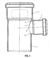
- the pipe connection piece shown in the figures is designed as a T-connection piece, comprising a substantially cylindrical main strand 1 and a secondary strand 2 which opens into the latter at substantially right angles.
- Both the main strand 1 and the secondary strand 2 are essentially cylindrical, wherein According to the invention, the mouth region of the secondary strand 2 in the main strand 1 is important.
- the penetrating there virtual cylinder of the main strand 1 and the secondary strand 2 form a section line 3 (average curve, fürdringungskurve).
- the cutting line is in the form of a spatial circular or elliptical curve, depending on the respective diameters of the virtual cylinders.
- the cutting line 3 has an upper vertex 8 in a vertical arrangement of the main strand 1 and merges into a peripheral region of 90 ° in lateral regions 9. In the further course, the cutting line 3 forms a lower region or vertex 10 opposite the vertex 8.
- the upper region of the cutting line 3 adjoining the apex 8 on both sides is provided with a tear-off edge 4, as in particular in FIGS Fig. 3 and 4 is apparent.
- the tear-off edge 4 extends with respect to its main strand side facing 6 on the cylinder surface line of the main strand 1, while the secondary strand 2 facing side 7 may be rounded, undercut, bevelled or provided with a chamfer. This will be on Fig. 4 directed. It is understood that the representations of Fig. 1 to 4 are schematic nature, so that the sake of clarity on the exact presentation of all the details of the trailing edge 4 has been omitted.
- the tear-off edge 4 extends on both sides (left and right running, in accordance with Fig. 2 ) of the apex 8 up to the peripheral regions 9 and decreases from a maximum height at the apex 8 to a minimum height at the peripheral regions 9. This minimum height can be 0 mm.
- this is provided (not shown in more detail) with a radius which extends from the lateral peripheral regions 9 to the region 10 opposite the apex 8.
- This optionally provided radius has the greatest value at the region 10 and runs in the region of the peripheral regions 9 to a value of 0 mm.
- the Fig. 5 shows a design variant, analogous to the representation of Fig. 4 , which differs in that the spoiler edge 4 projects into the main strand 1, so that the main strand 1 facing side 6 of the trailing edge 4 is at an angle to the adjacent cylindrical surface of the main strand 1. This can result in improved flow conditions.
Landscapes
- Engineering & Computer Science (AREA)
- General Engineering & Computer Science (AREA)
- Mechanical Engineering (AREA)
- Structural Engineering (AREA)
- Environmental & Geological Engineering (AREA)
- Health & Medical Sciences (AREA)
- Life Sciences & Earth Sciences (AREA)
- Hydrology & Water Resources (AREA)
- Public Health (AREA)
- Water Supply & Treatment (AREA)
- Rigid Pipes And Flexible Pipes (AREA)
- Mechanical Coupling Of Light Guides (AREA)
- Branch Pipes, Bends, And The Like (AREA)
- Footwear And Its Accessory, Manufacturing Method And Apparatuses (AREA)
- Building Environments (AREA)
- Joints With Sleeves (AREA)
- Laying Of Electric Cables Or Lines Outside (AREA)
- Sink And Installation For Waste Water (AREA)
Description
- Die Erfindung bezieht sich auf ein Rohrleitungsanschlussstück mit einem rohrförmigen Hauptstrang, in welchen ein rohrförmiger Nebenstrang mündet.
- Rohranschlussstücke der beschriebenen Art sind aus dem Stand der Technik in unterschiedlichen Ausgestaltungsformen vorbekannt, sie werden auch als Formstücke bezeichnet. Sie dienen insbesondere zur Abwasserableitung, insbesondere in Hausinstallationssystemen.
- Bei Abwasserleitungen, welche drucklos betrieben werden, stellt die Schalldämmung ein wesentliches Kriterium dar. Durch die nur teilweise Füllung des Rohrsystems mit Abwasser ergeben sich höchst komplizierte Strömungsverhältnisse, welche insbesondere bei Formstücken, bei denen die Strömungsrichtung geändert wird, zu unerwünschten Geräuschentwicklungen und Schallemissionen führen.
- Aus der den nächstkommenden Stand der Technik bildenden
US 4 121 914 A ist ein Rohrsystem vorbekannt, bei welchem der Hauptstrang wellenförmig ausgebildet ist, um die Hauptströmung aktiv umzulenken. Auf diese Weise soll ein Eintreten der Strömung in den Nebenstrang verhindert werden. - Die
JP 50 045446 A - Ein weiteres Rohrleitungssystem ist aus der
US 1 825 103 A vorbekannt. Dabei ist im Bereich der Einmündung bzw. Abzweigung von Kanälen eine strömungstechnische Verdickung vorgesehen, um unter Beibehaltung der laminaren Strömung Turbulenzen zu vermeiden. - Eine weitere Ausgestaltung eines Rohrleitungsanschlussstücks ist in der
US 1 629 208 A vorbeschrieben. Dabei handelt es sich um einen Teil eines Syphons, bei welchem eine Lippe des Hauptstranges bis unter die Unterkante des Nebenstranges reicht, um einen luftdichten Flüssigkeitsabschluss zu erzielen. - Die
US 2004/194840 A1 beschreibt einen Bogenabzweiger, bei welchem die Verschneidung eines Torus mit einem Zylinder entsteht. Die Schnittlinie ist dabei nicht weiter bezeichnet und wirkt keinesfalls als Abrisskante, zumal ein vertikaler Fall-Strang in einen horizontal liegenden Hauptstrang umgeleitet wird. - Die
GB 1 172 660 A - Der Erfindung liegt die Aufgabe zugrunde, ein Rohrleitungsanschlussstück der eingangs genannten Art zu schaffen, welches bei einfachem Aufbau und einfacher, kostengünstiger Herstellbarkeit ein hohes Maß an Schalldämmung sowie eine geringe Geräuschentwicklung im Rohrsystem bei Durchströmung von Fluid aufweist.
- Erfindungsgemäß wird die Aufgabe durch die Merkmalskombination des Anspruchs 1 gelöst, die Unteransprüche zeigen weitere vorteilhafte Ausgestaltungen der Erfindung.
- Erfindungsgemäß ist somit vorgesehen, dass zumindest ein Teilbereich einer Schnittlinie zwischen dem Hauptstrang und dem Nebenstrang in Form einer Abrisskante ausgebildet ist.
- Die erfindungsgemäß mit einer Abrisskante versehene Schnittlinie ergibt sich bei der geometrischen Durchdringung der zylindrischen Grundform des Hauptstranges durch die zylindrische Grundform des Nebenstranges im Bereich der Einmündung des Nebenstranges in den Hauptstrang. Es versteht sich, dass die Rohrleitungsanschlussstücke mit zusätzlichen Anschlussmuffen oder Ähnlichem versehen sein können. Diese können andere Querschnitte oder andere Dimensionierungen aufweisen, als der Einlaufbereich des Nebenstrangs in den Hauptstrang. Erfindungsgemäß ist die Schnittlinie oder Schnittkurve der Durchdringung der beiden zylindrischen Grundformen im Bereich des Einlaufs des Nebenstrangs in den Hauptstrang zu betrachten.
- Durch die erfindungsgemäß vorgesehene Abrisskante, welche sich zumindest über einen Teilbereich der Schnittlinie erstreckt, wird vermieden, dass Abwasser, welches durch den Hauptstrang strömt, in den Nebenstrang einläuft und auf die Wandung des Nebenstrangs aufprallt. Ein derartiges Einlaufen oder Aufprallen hat eine erhebliche Geräuschentwicklung zur Folge. Durch die Abrisskante wird dieser Effekt unterbunden. Die durch den Hauptstrang laufende Fluidströmung wird durch die Abrisskante daran gehindert, in den Nebenstrang einzudringen oder einzufließen, sondern verbleibt vielmehr, bedingt durch die Abrisskante, im Hauptstrang.
- Das erfindungsgemäße Rohrleitungsanschlussstück zeichnet sich somit durch eine sehr geringe Schallemission aus, auch wenn das abströmende Fluid des Hauptstranges diesen nur teilweise füllt und/oder sich in komplizierten Strömungsverhältnissen befindet, teils laminar, teils turbulent und/oder in spiralförmiger Strömung längs der Wandung des Hauptstrangs.
- Besonders vorteilhaft ist es, wenn erfindungsgemäß die Abrisskante so ausgebildet ist, dass hierdurch ein Ablösen der Strömung und eine Abweichung der Strömungsrichtung des Fluids im Hauptstrang gänzlich unterbunden werden.
- Der Hauptstrang des erfindungsgemäßen Rohrleitungsanschlussstücks ist bevorzugterweise so ausgebildet, dass dieser vertikal einbaubar ist, so dass der Hauptstrang als Fallrohr dient. Es ist jedoch auch möglich, andere Zuordnungen vorzunehmen. Auch ist es möglich, den Nebenstrang mittig oder exzentrisch und/oder in einem Winkel in den Hauptstrang einmünden zu lassen. Durch geeignete Ausgestaltung und Dimensionierung der Abrisskante ergeben sich auch hierbei die erfindungsgemäßen vorteilhaften Effekte.
- Erfindungsgemäß ist es besonders günstig, wenn die Abrisskante an einer Seite durch einen zylindrischen Bereich des Hauptstrangs und an einer anderen Seite durch einen Ansatz an einen zylindrischen Bereich des Nebenstrangs gebildet wird. Hierdurch ist es auf besonders einfache und kostengünstige Weise möglich, das erfindungsgemäße Rohrleitungsanschlussstück zu produzieren, beispielsweise als Kunststoff-Spritzgussteil. Die Ausprägung der Abrisskante kann durch ein einfaches Werkzeug mit einem Zugkern zur Erzeugung des Nebenstrangs hergestellt werden. Durch entsprechende Profilierung der vorderen Kante des Zugkerns wird dabei die Abrisskante auf zuverlässige und kostengünstige Weise erzeugt.
- Erfindungsgemäß kann die Abrisskante in bevorzugter Ausgestaltung an der dem Nebenstrang zugewandten Seite hinterschnitten oder mit einem Radius versehen sein. Die Ausgestaltungen können in optimaler Weise an die Nenndurchmesser sowohl des Hauptstrangs als auch des Nebenstrangs angepasst und entsprechend optimiert werden.
- Besonders günstig ist es, wenn die Abrisskante im Bereich ihrer maximalen Höhe vorzugsweise eine Höhe zwischen 1 mm und 2,5 mm aufweist. Es kann auch günstig sein, die Abrisskante so auszubilden, dass diese im Bereich ihrer maximalen Höhe eine Höhe zwischen 0,1 mm und 10 mm aufweist. Der Querschnitt der Abrisskante liegt bevorzugterweise in einem Winkel zwischen 10° und 40°, wobei der keilförmige Querschnitt der Abrisskante betrachtet wird. Erfindungsgemäß ist der keilförmige Abschnitt der Abrisskante mit einem Winkel zwischen 1° und 85° ausgebildet.
- Um eine optimale Wirkung zu erzielen, ist vorgesehen, dass sich die Abrisskante vom Scheitel der Schnittlinie oder Schnittkurve, die sich bei der Durchdringung der virtuellen Zylinder des Hauptstrangs und des Nebenstrangs ergibt, bis zu jeweils einem seitlichen Umfangbereich von 90° erstreckt. Die Abrisskante erstreckt sich somit, stirnseitig auf den Nebenstrang betrachtet, über einen oberen Halbkreis der Öffnung des Nebenstrangs in den Hauptstrang.
- Die Abrisskante weist im Scheitel die größte Höhe auf und nimmt zum jeweiligen seitlichen Bereich hin in ihrer Höhe ab, so dass sie auf eine Höhe von 0 mm ausläuft. Hierdurch kann der maximale Effekt der Verhinderung eines Strömungsabrisses erzielt werden.
- Zusätzlich zu der oben beschriebenen Höhe in einem Bereich von 1 mm bis 2,5 mm und dem Querschnittswinkel zwischen 10° und 40° können erfindungsgemäß weitere Abwandlungen vorgesehen sein. So ist es möglich, die Hinterschneidung der Abrisskante zu steigern, um einen besseren, nach unten gerichteten (bei einer vertikalen Installation des Hauptstrangs) Strömungseinlauf durch den Nebenstrang zu realisieren. Auch hierbei ist es vorteilhaft, dass die Abrisskante an ihrer dem Nebenstrang zugewandten Rückseite die durch den Nebenstrang in den Hauptstrang eintretende Strömung umlenkt, so dass diese nicht mit voller Geschwindigkeit auf die gegenüberliegende Wandung des Hauptstrangs aufprallt, sondern tangential an diese Wandung einläuft.
- Um sowohl die Strömung des Hauptstranges als auch die einlaufende Strömung des Nebenstrangs in besonders günstiger Weise zu beeinflussen und schalldämmend zu führen, kann es weiterhin vorteilhaft sein, wenn die Schnittlinie oder Schnittkurve in ihrem unteren, nicht mit der Abrisskante versehenen Bereich mit einem Radius versehen ist. Auch hierbei kann es günstig sein, den Radius vom seitlichen Bereich (90° zum Scheitel versetzt) mit 0 mm beginnen zu lassen und an dem unteren Scheitel mit einem Maximalwert auszuführen. Hierdurch ergibt sich eine bessere Umlenkung der durch den Nebenstrang einlaufenden Fluidströmung sowie ein besseres Ablaufen geringfügiger Fluidmengen, die dann trotz der Abrisskante in den Nebenstrang eintreten sollten. Der Radius kann beispielsweise einen Maximalwert von 10 mm im unteren Scheitelpunkt aufweisen und auf 0 mm im seitlichen Scheitelpunkt zurückgehen.
- Die Kante der Abrisskante selbst ist bevorzugterweise sehr scharfkantig ausgeführt. Dies ergibt sich durch die beschriebene Herstellungsweise mit einem Zugkern weitgehend von selbst.
- Das erfindungsgemäße Rohrleitungsanschlussstück ist, wie erläutert, nicht auf eine Anordnung beschränkt, bei welcher der Nebenstrang hinsichtlich seiner Mittelachse senkrecht auf die Mittelachse des Hauptstranges auftrifft. Vielmehr sind auch in einem Winkel angeordnete Ausgestaltungsvarianten möglicht.
- Bei einem Einsatz des erfindungsgemäßen Rohrleitungsanschlussstücks in einer nicht-vertikalen Einbaulage kann es günstig sein, die Dimensionierung und Anordnung der Abrisskante längs der Schnittkurve bzw. Schnittlinie zu verschieben, um die geänderte Strömungsrichtung zu berücksichtigen.
- Im Folgenden wird die Erfindung anhand eines Ausführungsbeispiels in Verbindung mit der Zeichnung beschrieben. Dabei zeigt:
- Fig. 1
- eine Seiten-Schnittansicht eines erfindungsgemäßen Rohrleitungsanschlussstücks,
- Fig. 2
- eine stirnseitige Ansicht gemäß Blickrichtung von rechts der
Fig. 1 , - Fig. 3
- eine vergrößerte Detail-Schnittansicht gemäß
Fig. 1 , - Fig. 4
- eine nochmals vergrößerte Detail-Schnittansicht, analog
Fig. 3 , und - Fig. 5
- eine weitere Darstellung, analog den
Fig. 3 und4 , bei welcher die Abrisskante 4 zumindest teilweise in den Freiraum des Hauptstranges 1 ragt. - Das in den Figuren gezeigte Rohrleitungsanschlussstück ist als T-Anschlussstück ausgebildet, es umfasst einen im Wesentlichen zylindrischen Hauptstrang 1 sowie einen in diesen im Wesentlichen im rechten Winkel einmündenden Nebenstrang 2. Sowohl der Hauptstrang 1 als auch der Nebenstrang 2 sind im Wesentlichen zylindrisch ausgebildet, wobei erfindungsgemäß der Mündungsbereich des Nebenstrangs 2 in den Hauptstrang 1 wichtig ist. Die sich dort durchdringenden virtuellen Zylinder des Hauptstrangs 1 und des Nebenstrangs 2 bilden eine Schnittlinie 3 (Schnittkurve, Durchdringungskurve). Bei einer rechtwinkligen Einmündung und bei zylindrischer Ausgestaltung des Hauptstrangs 1 und des Nebenstrangs 2 ist die Schnittlinie in Form einer räumlichen kreisrunden oder elliptischen Kurve ausgebildet, abhängig von den jeweiligen Durchmessern der virtuellen Zylinder.
- Die Schnittlinie 3 weist bei vertikaler Anordnung des Hauptstrangs 1 einen oberen Scheitel 8 auf und geht in einen Umfangsbereich von 90° in seitliche Bereiche 9 über. Im weiteren Verlauf bildet die Schnittlinie 3 einen unteren, dem Scheitel 8 gegenüberliegenden Bereich oder Scheitel 10.
- Erfindungsgemäß ist der obere, beidseitig an den Scheitel 8 angrenzende Bereich der Schnittlinie 3 mit einer Abrisskante 4 versehen, so wie dies insbesondere in den
Fig. 3 und4 ersichtlich ist. Die Abrisskante 4 erstreckt sich hinsichtlich ihrer dem Hauptstrang zugewandten Seite 6 auf der Zylindermantellinie des Hauptstrangs 1, während die dem Nebenstrang 2 zugewandte Seite 7 abgerundet, hinterschnitten, abgeschrägt oder mit einer Fase versehen sein kann. Diesbezüglich wird aufFig. 4 verwiesen. Es versteht sich, dass die Darstellungen derFig. 1 bis 4 schematischer Art sind, so dass der Übersichtlichkeit halber auf die exakte Darstellung sämtlicher Details der Abrisskante 4 verzichtet wurde. - Die Abrisskante 4 erstreckt sich beidseitig (links und rechts verlaufend, gemäß
Fig. 2 ) des Scheitels 8 bis zu den Umfangsbereichen 9 und nimmt von einer maximalen Höhe am Scheitel 8 zu einer minimalen Höhe an den Umfangsbereichen 9 ab. Diese minimale Höhe kann 0 mm betragen. - Im unteren Bereich der Schnittlinie 3 ist diese (nicht näher dargestellt) mit einem Radius versehen, welcher sich von den seitlichen Umfangsbereichen 9 zu dem dem Scheitel 8 gegenüberliegenden Bereich 10 erstreckt. Dieser fakultativ vorgesehene Radius hat am Bereich 10 den größten Wert und läuft im Bereich der Umfangsbereiche 9 auf einen Wert von 0 mm aus.
- Die
Fig. 5 zeigt eine Ausgestaltungsvariante, analog der Darstellung derFig. 4 , welche sich darin unterscheidet, dass die Abrisskante 4 in den Hauptstrang 1 ragt, so dass die dem Hauptstrang 1 zugewandte Seite 6 der Abrisskante 4 in einem Winkel zu der benachbarten Zylinderfläche des Hauptstrangs 1 steht. Hierdurch können sich verbesserte Strömungsverhältnisse ergeben. -
- 1
- Hauptstrang/Fallstrang
- 2
- Nebenstrang/Seitenstrang
- 3
- Schnittlinie
- 4
- Abrisskante
- 5
- Strömungsrichtung des Hauptstrangs
- 6
- Seite der Abrisskante 4
- 7
- Seite der Abrisskante 4
- 8
- Scheitel
- 9
- Umfangsbereich von 90°
- 10
- dem Scheitel 8 gegenüberliegender Bereich
Claims (13)
- Rohrleitungsanschlussstück mit einem rohrförmigen Hauptstrang (1), in welchen ein rohrförmiger Nebenstrang (2) mündet,
wobei zumindest ein Teilbereich einer Schnittlinie (3) zwischen dem Hauptstrang (1) und dem Nebenstrang (2) in Form einer Abrisskante (4) ausgebildet ist
und die Abrisskante (4) so ausgebildet ist, dass eine Abweichung der Strömungsrichtung (5) eines Fluids im Hauptstrang (1) und ein Eintreten von Fluid in den Nebenstrang (2) vermieden werden,
dadurch gekennzeichnet,
dass die Abrisskante (4) im Querschnitt keilförmig ausgebildet ist und einen Winkel zwischen 1° und 85° aufweist;
dass sich die Abrisskante (4) vom oberen Scheitel (8) der Schnittlinie (3) bis zu jeweils einem seitlichen Umfangsbereich (9) von 90° erstreckt; und
dass die Abrisskante (4) im oberen Scheitel (8) die größte Höhe und im Umfangsbereich (9) von 90° eine Höhe von 0 mm aufweist. - Rohrleitungsanschlussstück nach Anspruch 1, dadurch gekennzeichnet, dass die Abrisskante (4) an einer Seite (6) durch einen zylindrischen Bereich des Hauptstrangs (1) und an der anderen Seite (7) durch einen Ansatz an einem zylindrischen Bereich des Nebenstrangs (2) gebildet wird.
- Rohrleitungsanschlussstück nach Anspruch 2, dadurch gekennzeichnet, dass die Abrisskante (4) an der dem Nebenstrang (2) zugewandten Seite hinterschnitten ist.
- Rohrleitungsanschlussstück nach Anspruch 2, dadurch gekennzeichnet, dass die Abrisskante (4) an der dem Nebenstrang (2) zugewandten Seite mit einem Radius versehen ist.
- Rohrleitungsanschlussstück nach Anspruch 1, dadurch gekennzeichnet, dass die Abrisskante (4) an der dem Nebenstrang (2) abgewandten Seite (6) in einem Winkel in den Hauptstrang (1) ragt.
- Rohrleitungsanschlussstück nach einem der Ansprüche 1 bis 5, dadurch gekennzeichnet, dass die Abrisskante (4) eine Höhe zwischen 1 mm und 2,5 mm aufweist.
- Rohrleitungsanschlussstück nach einem der Ansprüche 1 bis 5, dadurch gekennzeichnet, dass die Abrisskante (4) eine Höhe zwischen 0,1 mm und 10 mm aufweist.
- Rohrleitungsanschlussstück nach einem der Ansprüche 1 bis 7, dadurch gekennzeichnet, dass die Abrisskante (4) im Querschnitt einen Winkel zwischen 10° und 40° aufweist.
- Rohrleitungsanschlussstück nach einem der Ansprüche 1 bis 8, dadurch gekennzeichnet, dass die Schnittlinie (3) an dem nicht mit der Abrisskante (4) versehenen Bereich mit einem Radius versehen ist.
- Rohrleitungsanschlussstück nach Anspruch 9, dadurch gekennzeichnet, dass der Radius am Umfangsbereich (9) der Schnittlinie (3) von 90° 0 mm beträgt und in dem dem Scheitel gegenüberliegenden Bereich (10) einen Maximalwert aufweist.
- Rohrleitungsanschlussstück nach einem der Ansprüche 1 bis 10, dadurch gekennzeichnet, dass die Abrisskante (4) aus demselben Material gefertigt ist, wie das Rohrleitungsanschlussstück.
- Rohrleitungsanschlussstück nach einem der Ansprüche 1 bis 10, dadurch gekennzeichnet, dass die Abrisskante (4) aus einem anderen Material gefertigt ist, als das Rohrleitungsanschlussstück.
- Rohrleitungsanschlussstück nach Anspruch 12, dadurch gekennzeichnet, dass die Abrisskante (4) mittels einer Mehrkomponententechnik gefertigt ist.
Priority Applications (2)
| Application Number | Priority Date | Filing Date | Title |
|---|---|---|---|
| SI200730059T SI1860364T1 (sl) | 2006-05-23 | 2007-05-23 | Cevovodni priključni kos |
| PL07010243T PL1860364T3 (pl) | 2006-05-23 | 2007-05-23 | Złączka przewodu rurowego |
Applications Claiming Priority (1)
| Application Number | Priority Date | Filing Date | Title |
|---|---|---|---|
| DE102006024254A DE102006024254B3 (de) | 2006-05-23 | 2006-05-23 | Rohrleitungsanschlussstück |
Publications (2)
| Publication Number | Publication Date |
|---|---|
| EP1860364A1 EP1860364A1 (de) | 2007-11-28 |
| EP1860364B1 true EP1860364B1 (de) | 2009-05-13 |
Family
ID=38352433
Family Applications (1)
| Application Number | Title | Priority Date | Filing Date |
|---|---|---|---|
| EP07010243A Active EP1860364B1 (de) | 2006-05-23 | 2007-05-23 | Rohrleitungsanschlussstück |
Country Status (7)
| Country | Link |
|---|---|
| EP (1) | EP1860364B1 (de) |
| AT (1) | ATE431518T1 (de) |
| DE (2) | DE102006024254B3 (de) |
| ES (1) | ES2327458T3 (de) |
| NO (1) | NO340659B1 (de) |
| PL (1) | PL1860364T3 (de) |
| SI (1) | SI1860364T1 (de) |
Families Citing this family (2)
| Publication number | Priority date | Publication date | Assignee | Title |
|---|---|---|---|---|
| CN107237374B (zh) * | 2016-12-31 | 2023-03-31 | 王凤蕊 | 一种建筑用模块化同层排水装置及其安装方法 |
| CN112031089B (zh) * | 2020-05-22 | 2021-09-10 | 康泰塑胶科技集团有限公司 | 一种建筑卫生间用不降板同层排水系统 |
Family Cites Families (7)
| Publication number | Priority date | Publication date | Assignee | Title |
|---|---|---|---|---|
| US1629208A (en) | 1925-08-27 | 1927-05-17 | Ernst Daniel Lot | Soil fitting |
| US1825103A (en) | 1929-03-21 | 1931-09-29 | Carrier Engineering Corp | Conduit |
| GB1172660A (en) | 1968-12-02 | 1969-12-03 | Marley Tile Co Ltd | Improvements in Branch Pipes. |
| JPS5718015B2 (de) | 1973-08-28 | 1982-04-14 | ||
| DE2707681C3 (de) | 1976-02-25 | 1980-11-20 | Kubota Ltd., Osaka (Japan) | Umlenkrohr |
| DE20302761U1 (de) * | 2003-02-20 | 2003-04-30 | Franz Viegener II GmbH & Co. KG, 57439 Attendorn | Blindstopfen und Verbindungsanordnung |
| US7178557B2 (en) | 2003-03-26 | 2007-02-20 | Spears Manufacturing Co. | CPVC drain waste and vent fittings |
-
2006
- 2006-05-23 DE DE102006024254A patent/DE102006024254B3/de not_active Expired - Fee Related
-
2007
- 2007-05-23 NO NO20072623A patent/NO340659B1/no unknown
- 2007-05-23 SI SI200730059T patent/SI1860364T1/sl unknown
- 2007-05-23 EP EP07010243A patent/EP1860364B1/de active Active
- 2007-05-23 AT AT07010243T patent/ATE431518T1/de active
- 2007-05-23 ES ES07010243T patent/ES2327458T3/es active Active
- 2007-05-23 PL PL07010243T patent/PL1860364T3/pl unknown
- 2007-05-23 DE DE502007000715T patent/DE502007000715D1/de active Active
Also Published As
| Publication number | Publication date |
|---|---|
| ES2327458T3 (es) | 2009-10-29 |
| PL1860364T3 (pl) | 2009-10-30 |
| EP1860364A1 (de) | 2007-11-28 |
| SI1860364T1 (sl) | 2009-10-31 |
| ATE431518T1 (de) | 2009-05-15 |
| NO340659B1 (no) | 2017-05-29 |
| DE502007000715D1 (de) | 2009-06-25 |
| DE102006024254B3 (de) | 2007-09-20 |
| NO20072623L (no) | 2007-11-26 |
Similar Documents
| Publication | Publication Date | Title |
|---|---|---|
| EP2098647B1 (de) | Anschlussarmatur | |
| EP2952752B1 (de) | Umlenkbogen | |
| EP2230359A2 (de) | Bausatz für eine Verbindung eines Inspektions-Schachtes mit einer Abfluss-Leitung | |
| DE3146803C2 (de) | Spritz-Schutzring für Rohrflansche | |
| EP2525002A1 (de) | Leitungszweigstück für Fallleitungen | |
| EP3921551A1 (de) | Winkelstück zum fluidkommunizierenden verbinden von fluidleitungen eines fahrzeugs | |
| EP1882786B1 (de) | Umlenkbogen für eine Falleitung | |
| EP1860364A1 (de) | Rohrleitungsanschlussstück | |
| EP2226545B1 (de) | Rohrleitungselement und Verwendung dafür | |
| WO2018141525A1 (de) | Umlenkbogen | |
| EP2518847A2 (de) | Gehàusedurchführung | |
| EP2447424A1 (de) | Leitungszweigstück für Fallleitungen | |
| AT402438B (de) | Durchflussbegrenzer für schlaucharmaturen | |
| EP2020551A2 (de) | Gehäuse für ein Be- und Entlüftungsventil für Rohrleitungen bzw. Armaturen | |
| DE202011110778U1 (de) | Leitungszweigstück für Fallleitungen | |
| EP1617124B1 (de) | Rohrstück, Abwasser- oder Schachtbauteil und Verfahren zu deren Herstellung | |
| EP2177680A1 (de) | Rückstauverschluss | |
| DE29818296U1 (de) | Rohrmodul | |
| EP4296489B1 (de) | Lufteinlass | |
| DE10307599B4 (de) | Abwasserschacht als Kombinationsschacht | |
| DE3326592C2 (de) | ||
| DE102004024371B4 (de) | Fülleinrichtung mit einem Füllrohr | |
| DE102004001375A1 (de) | Vorrichtung zur Veränderung des freien Strömungsquerschnitts eines Rohres oder Kanals | |
| DE1484876C (de) | Durchlaufrinne eines Regenüberlaufs in einem Abwasserkanal | |
| DE3102119A1 (de) | Vorgefertigtes teil fuer durchlaufgerinne in kanalschaechten |
Legal Events
| Date | Code | Title | Description |
|---|---|---|---|
| PUAI | Public reference made under article 153(3) epc to a published international application that has entered the european phase |
Free format text: ORIGINAL CODE: 0009012 |
|
| AK | Designated contracting states |
Kind code of ref document: A1 Designated state(s): AT BE BG CH CY CZ DE DK EE ES FI FR GB GR HU IE IS IT LI LT LU LV MC MT NL PL PT RO SE SI SK TR |
|
| AX | Request for extension of the european patent |
Extension state: AL BA HR MK YU |
|
| 17P | Request for examination filed |
Effective date: 20080311 |
|
| AKX | Designation fees paid |
Designated state(s): AT BE BG CH CY CZ DE DK EE ES FI FR GB GR HU IE IS IT LI LT LU LV MC MT NL PL PT RO SE SI SK TR |
|
| 17Q | First examination report despatched |
Effective date: 20080917 |
|
| GRAP | Despatch of communication of intention to grant a patent |
Free format text: ORIGINAL CODE: EPIDOSNIGR1 |
|
| GRAS | Grant fee paid |
Free format text: ORIGINAL CODE: EPIDOSNIGR3 |
|
| GRAA | (expected) grant |
Free format text: ORIGINAL CODE: 0009210 |
|
| AK | Designated contracting states |
Kind code of ref document: B1 Designated state(s): AT BE BG CH CY CZ DE DK EE ES FI FR GB GR HU IE IS IT LI LT LU LV MC MT NL PL PT RO SE SI SK TR |
|
| REG | Reference to a national code |
Ref country code: GB Ref legal event code: FG4D Free format text: NOT ENGLISH |
|
| REG | Reference to a national code |
Ref country code: CH Ref legal event code: EP |
|
| REG | Reference to a national code |
Ref country code: IE Ref legal event code: FG4D |
|
| REF | Corresponds to: |
Ref document number: 502007000715 Country of ref document: DE Date of ref document: 20090625 Kind code of ref document: P |
|
| REG | Reference to a national code |
Ref country code: SE Ref legal event code: TRGR |
|
| REG | Reference to a national code |
Ref country code: ES Ref legal event code: FG2A Ref document number: 2327458 Country of ref document: ES Kind code of ref document: T3 |
|
| PG25 | Lapsed in a contracting state [announced via postgrant information from national office to epo] |
Ref country code: PT Free format text: LAPSE BECAUSE OF FAILURE TO SUBMIT A TRANSLATION OF THE DESCRIPTION OR TO PAY THE FEE WITHIN THE PRESCRIBED TIME-LIMIT Effective date: 20090913 Ref country code: FI Free format text: LAPSE BECAUSE OF FAILURE TO SUBMIT A TRANSLATION OF THE DESCRIPTION OR TO PAY THE FEE WITHIN THE PRESCRIBED TIME-LIMIT Effective date: 20090513 Ref country code: LT Free format text: LAPSE BECAUSE OF FAILURE TO SUBMIT A TRANSLATION OF THE DESCRIPTION OR TO PAY THE FEE WITHIN THE PRESCRIBED TIME-LIMIT Effective date: 20090513 |
|
| REG | Reference to a national code |
Ref country code: PL Ref legal event code: T3 |
|
| BERE | Be: lapsed |
Owner name: POLOPLAST GMBH & CO. KG Effective date: 20090531 |
|
| PG25 | Lapsed in a contracting state [announced via postgrant information from national office to epo] |
Ref country code: LV Free format text: LAPSE BECAUSE OF FAILURE TO SUBMIT A TRANSLATION OF THE DESCRIPTION OR TO PAY THE FEE WITHIN THE PRESCRIBED TIME-LIMIT Effective date: 20090513 Ref country code: IS Free format text: LAPSE BECAUSE OF FAILURE TO SUBMIT A TRANSLATION OF THE DESCRIPTION OR TO PAY THE FEE WITHIN THE PRESCRIBED TIME-LIMIT Effective date: 20090913 |
|
| REG | Reference to a national code |
Ref country code: IE Ref legal event code: FD4D |
|
| REG | Reference to a national code |
Ref country code: HU Ref legal event code: AG4A Ref document number: E006192 Country of ref document: HU |
|
| PG25 | Lapsed in a contracting state [announced via postgrant information from national office to epo] |
Ref country code: MC Free format text: LAPSE BECAUSE OF NON-PAYMENT OF DUE FEES Effective date: 20090531 |
|
| PG25 | Lapsed in a contracting state [announced via postgrant information from national office to epo] |
Ref country code: IE Free format text: LAPSE BECAUSE OF FAILURE TO SUBMIT A TRANSLATION OF THE DESCRIPTION OR TO PAY THE FEE WITHIN THE PRESCRIBED TIME-LIMIT Effective date: 20090513 Ref country code: DK Free format text: LAPSE BECAUSE OF FAILURE TO SUBMIT A TRANSLATION OF THE DESCRIPTION OR TO PAY THE FEE WITHIN THE PRESCRIBED TIME-LIMIT Effective date: 20090513 Ref country code: EE Free format text: LAPSE BECAUSE OF FAILURE TO SUBMIT A TRANSLATION OF THE DESCRIPTION OR TO PAY THE FEE WITHIN THE PRESCRIBED TIME-LIMIT Effective date: 20090513 |
|
| PG25 | Lapsed in a contracting state [announced via postgrant information from national office to epo] |
Ref country code: SK Free format text: LAPSE BECAUSE OF FAILURE TO SUBMIT A TRANSLATION OF THE DESCRIPTION OR TO PAY THE FEE WITHIN THE PRESCRIBED TIME-LIMIT Effective date: 20090513 |
|
| PLBE | No opposition filed within time limit |
Free format text: ORIGINAL CODE: 0009261 |
|
| STAA | Information on the status of an ep patent application or granted ep patent |
Free format text: STATUS: NO OPPOSITION FILED WITHIN TIME LIMIT |
|
| PG25 | Lapsed in a contracting state [announced via postgrant information from national office to epo] |
Ref country code: BG Free format text: LAPSE BECAUSE OF FAILURE TO SUBMIT A TRANSLATION OF THE DESCRIPTION OR TO PAY THE FEE WITHIN THE PRESCRIBED TIME-LIMIT Effective date: 20090813 |
|
| 26N | No opposition filed |
Effective date: 20100216 |
|
| PG25 | Lapsed in a contracting state [announced via postgrant information from national office to epo] |
Ref country code: BE Free format text: LAPSE BECAUSE OF NON-PAYMENT OF DUE FEES Effective date: 20090531 |
|
| REG | Reference to a national code |
Ref country code: FR Ref legal event code: ST Effective date: 20100531 |
|
| PG25 | Lapsed in a contracting state [announced via postgrant information from national office to epo] |
Ref country code: FR Free format text: LAPSE BECAUSE OF NON-PAYMENT OF DUE FEES Effective date: 20090715 |
|
| PG25 | Lapsed in a contracting state [announced via postgrant information from national office to epo] |
Ref country code: GR Free format text: LAPSE BECAUSE OF FAILURE TO SUBMIT A TRANSLATION OF THE DESCRIPTION OR TO PAY THE FEE WITHIN THE PRESCRIBED TIME-LIMIT Effective date: 20090814 |
|
| PG25 | Lapsed in a contracting state [announced via postgrant information from national office to epo] |
Ref country code: RO Free format text: LAPSE BECAUSE OF FAILURE TO SUBMIT A TRANSLATION OF THE DESCRIPTION OR TO PAY THE FEE WITHIN THE PRESCRIBED TIME-LIMIT Effective date: 20090513 |
|
| PG25 | Lapsed in a contracting state [announced via postgrant information from national office to epo] |
Ref country code: IT Free format text: LAPSE BECAUSE OF NON-PAYMENT OF DUE FEES Effective date: 20100523 |
|
| PG25 | Lapsed in a contracting state [announced via postgrant information from national office to epo] |
Ref country code: LU Free format text: LAPSE BECAUSE OF NON-PAYMENT OF DUE FEES Effective date: 20090523 Ref country code: MT Free format text: LAPSE BECAUSE OF FAILURE TO SUBMIT A TRANSLATION OF THE DESCRIPTION OR TO PAY THE FEE WITHIN THE PRESCRIBED TIME-LIMIT Effective date: 20090513 |
|
| PG25 | Lapsed in a contracting state [announced via postgrant information from national office to epo] |
Ref country code: TR Free format text: LAPSE BECAUSE OF FAILURE TO SUBMIT A TRANSLATION OF THE DESCRIPTION OR TO PAY THE FEE WITHIN THE PRESCRIBED TIME-LIMIT Effective date: 20090513 |
|
| PG25 | Lapsed in a contracting state [announced via postgrant information from national office to epo] |
Ref country code: CY Free format text: LAPSE BECAUSE OF FAILURE TO SUBMIT A TRANSLATION OF THE DESCRIPTION OR TO PAY THE FEE WITHIN THE PRESCRIBED TIME-LIMIT Effective date: 20090513 |
|
| REG | Reference to a national code |
Ref country code: CH Ref legal event code: PL |
|
| PG25 | Lapsed in a contracting state [announced via postgrant information from national office to epo] |
Ref country code: CH Free format text: LAPSE BECAUSE OF NON-PAYMENT OF DUE FEES Effective date: 20110531 Ref country code: LI Free format text: LAPSE BECAUSE OF NON-PAYMENT OF DUE FEES Effective date: 20110531 |
|
| PGFP | Annual fee paid to national office [announced via postgrant information from national office to epo] |
Ref country code: NL Payment date: 20240522 Year of fee payment: 18 |
|
| PGFP | Annual fee paid to national office [announced via postgrant information from national office to epo] |
Ref country code: GB Payment date: 20240522 Year of fee payment: 18 |
|
| PGFP | Annual fee paid to national office [announced via postgrant information from national office to epo] |
Ref country code: CZ Payment date: 20240510 Year of fee payment: 18 |
|
| PGFP | Annual fee paid to national office [announced via postgrant information from national office to epo] |
Ref country code: SI Payment date: 20240513 Year of fee payment: 18 |
|
| PGFP | Annual fee paid to national office [announced via postgrant information from national office to epo] |
Ref country code: PL Payment date: 20240509 Year of fee payment: 18 |
|
| PGFP | Annual fee paid to national office [announced via postgrant information from national office to epo] |
Ref country code: SE Payment date: 20240522 Year of fee payment: 18 Ref country code: HU Payment date: 20240524 Year of fee payment: 18 |
|
| PGFP | Annual fee paid to national office [announced via postgrant information from national office to epo] |
Ref country code: DE Payment date: 20250520 Year of fee payment: 19 |
|
| PGFP | Annual fee paid to national office [announced via postgrant information from national office to epo] |
Ref country code: ES Payment date: 20250616 Year of fee payment: 19 |
|
| PGFP | Annual fee paid to national office [announced via postgrant information from national office to epo] |
Ref country code: IT Payment date: 20250530 Year of fee payment: 19 |
|
| PGFP | Annual fee paid to national office [announced via postgrant information from national office to epo] |
Ref country code: AT Payment date: 20250519 Year of fee payment: 19 |
|
| REG | Reference to a national code |
Ref country code: NL Ref legal event code: MM Effective date: 20250601 |
|
| PG25 | Lapsed in a contracting state [announced via postgrant information from national office to epo] |
Ref country code: HU Free format text: LAPSE BECAUSE OF NON-PAYMENT OF DUE FEES Effective date: 20250524 |
|
| PG25 | Lapsed in a contracting state [announced via postgrant information from national office to epo] |
Ref country code: CZ Free format text: LAPSE BECAUSE OF NON-PAYMENT OF DUE FEES Effective date: 20250523 Ref country code: SE Free format text: LAPSE BECAUSE OF NON-PAYMENT OF DUE FEES Effective date: 20250524 |
|
| REG | Reference to a national code |
Ref country code: SE Ref legal event code: EUG |
|
| GBPC | Gb: european patent ceased through non-payment of renewal fee |
Effective date: 20250523 |
|
| PG25 | Lapsed in a contracting state [announced via postgrant information from national office to epo] |
Ref country code: NL Free format text: LAPSE BECAUSE OF NON-PAYMENT OF DUE FEES Effective date: 20250601 |
|
| PG25 | Lapsed in a contracting state [announced via postgrant information from national office to epo] |
Ref country code: GB Free format text: LAPSE BECAUSE OF NON-PAYMENT OF DUE FEES Effective date: 20250523 |