EP1860403A2 - Verfahren zur Entfernung von Einflüssen der Bewegungen einer kardanischen Aufhängung auf Navigationsdaten - Google Patents
Verfahren zur Entfernung von Einflüssen der Bewegungen einer kardanischen Aufhängung auf Navigationsdaten Download PDFInfo
- Publication number
- EP1860403A2 EP1860403A2 EP07108872A EP07108872A EP1860403A2 EP 1860403 A2 EP1860403 A2 EP 1860403A2 EP 07108872 A EP07108872 A EP 07108872A EP 07108872 A EP07108872 A EP 07108872A EP 1860403 A2 EP1860403 A2 EP 1860403A2
- Authority
- EP
- European Patent Office
- Prior art keywords
- data
- gimbal
- axes
- motion
- egi
- Prior art date
- Legal status (The legal status is an assumption and is not a legal conclusion. Google has not performed a legal analysis and makes no representation as to the accuracy of the status listed.)
- Granted
Links
Images


Classifications
-
- G—PHYSICS
- G01—MEASURING; TESTING
- G01C—MEASURING DISTANCES, LEVELS OR BEARINGS; SURVEYING; NAVIGATION; GYROSCOPIC INSTRUMENTS; PHOTOGRAMMETRY OR VIDEOGRAMMETRY
- G01C21/00—Navigation; Navigational instruments not provided for in groups G01C1/00 - G01C19/00
- G01C21/10—Navigation; Navigational instruments not provided for in groups G01C1/00 - G01C19/00 by using measurements of speed or acceleration
- G01C21/12—Navigation; Navigational instruments not provided for in groups G01C1/00 - G01C19/00 by using measurements of speed or acceleration executed aboard the object being navigated; Dead reckoning
- G01C21/16—Navigation; Navigational instruments not provided for in groups G01C1/00 - G01C19/00 by using measurements of speed or acceleration executed aboard the object being navigated; Dead reckoning by integrating acceleration or speed, i.e. inertial navigation
- G01C21/18—Stabilised platforms, e.g. by gyroscope
-
- H—ELECTRICITY
- H01—ELECTRIC ELEMENTS
- H01Q—ANTENNAS, i.e. RADIO AERIALS
- H01Q1/00—Details of, or arrangements associated with, antennas
- H01Q1/12—Supports; Mounting means
- H01Q1/18—Means for stabilising antennas on an unstable platform
Definitions
- the present invention relates to velocity and position data frame of references, and more particularly, to removing effects of gimbal rotations from angular rate and attitude data.
- Precision imaging systems such as RADARS (radio detection and ranging), LIDARs (light detection and ranging), etc., are generally mounted on gimbals so that the detection device will remain suspended in a plane regardless of any motion of a vehicle on which the device sits. This allows the detection device to produce high resolution imagery that is not distorted due to the vehicle movements or accelerations.
- the detection device usually requires accurate velocity data of the detection device for image stabilization purposes.
- such radar or lidar systems will have inertial sensors like gyroscopes and accelerometers mounted within the imaging system's gimbal assembly and next to the detection device of the imaging system to provide vehicle position and velocity data in the gimbal frame of reference. While this solves the need of the imaging system for accurate attitude data (e.g., position of aircraft or vehicle relative to a frame of reference-the horizon or direction of motion), velocity and position data at the detection device, this data does not reflect the actual vehicle attitude, velocity, or position since the inertial sensors are mounted on the gimbal.
- the vehicle typically has another set of accelerometers and gyroscopes that provide attitude, velocity and position data of the vehicle.
- a method for transforming gimbaled data output from an inertial sensor positioned on a gimbaled assembly within a moving vehicle into a frame of reference with respect to the moving vehicle includes receiving data from an inertial sensor mounted on a gimbal assembly that is positioned within a moving vehicle. Motion of the inertial sensor is due to motion of the gimbal assembly and motion of the moving vehicle, and thus data output from the inertial sensor reflects the motion of the gimbal assembly and the motion of the moving vehicle. The method further includes removing effects of the motion of the gimbal assembly from the data to produce data approximately reflecting motion of the moving vehicle.
- the method includes receiving data output from the inertial sensor positioned on the gimbaled assembly.
- the data reflects motion of the gimbaled assembly and motion of the moving vehicle.
- the method also includes receiving data output from an angular sensor that indicates an angular offset of the gimbaled assembly with respect to the moving vehicle and then synchronizing the data output from the inertial sensor and the data output from the angular sensor.
- the method further includes removing effects of the motion of the gimbaled assembly from the data output from the inertial sensor to produce data approximately reflecting motion of the moving vehicle.
- the embodiments may take the form of a radar assembly.
- the radar assembly includes a radar device mounted on a gimbaled assembly, an Embedded Global Positioning System/Inertial Navigation System (EGI) mounted on the gimbaled assembly, and a processor.
- EGI Embedded Global Positioning System/Inertial Navigation System
- the EGI provides data in a gimbaled frame of reference to the radar device, and the processor also receives the data in the gimbaled frame of reference and removes effects of gimbaled motion within the data.
- RADARs radio detection and ranging
- LIDARs light detection and ranging
- SAR Synthetic Aperture Radar
- FIG. 1 illustrates an example of a SAR antenna 100.
- the SAR antenna 100 is mounted on a gimbal assembly 102 so that the antenna 100 will remain suspended in a host vehicle, such as an aircraft like a plane, helicopter or blimp, a spacecraft or a ground vehicle, regardless of any motion of a vehicle on which the antenna 100 sits.
- a host vehicle such as an aircraft like a plane, helicopter or blimp, a spacecraft or a ground vehicle, regardless of any motion of a vehicle on which the antenna 100 sits.
- the antenna 100 to produce high resolution imagery that is not distorted due to the vehicle movements or accelerations.
- the gimbal only provides roll axis control.
- the SAR antenna 100 requires precise antenna velocity/position (relative to targets on the earth) over short periods of time for image stabilization purposes.
- an Embedded Global Positioning System (GPS)/Inertial Navigation System (INS) (referred to as an "EGI") 104 is mounted directly on the antenna gimbal assembly 102 to provide such data in the gimbal frame of reference to the antenna 100.
- GPS Global Positioning System
- INS Intelligent Navigation System
- the EGI 104 provides precision navigation information by integrating GPS satellite signals and INS data.
- the EGI 104 includes inertial sensors like gyroscopes and accelerometers to provide vehicle position and velocity data to the SAR antenna 100.
- an INS that is not coupled with a GPS may also be mounted on the antenna gimbal assembly 102 to provide proper data to the antenna 100.
- GPS data such as by employing an EGI on the assembly, may not be necessary in all applications.
- GPS data may be used, for example, as an accurate, stable, common time line to synchronize independent systems. Other techniques may be possible as well, however, GPS data satisfies needed accuracy.
- only time data within the GPS data may be used. In other embodiments, position, velocity and time data may be used depending on specific applications of the antenna.
- the EGI 104 thus provides accurate velocity, attitude and acceleration data of the phase center of the antenna relative to an Earth-based frame of reference (e.g., local-level) that is required for SAR processing. Such data does not reflect the vehicle attitude since the EGI 104 is mounted on the moving gimbal.
- Earth-based frame of reference e.g., local-level
- data output from the EGI 104 is processed to provide actual vehicle navigation data (or data in the vehicle's frame of reference), thus eliminating the need for a separate set of inertial sensors that provide vehicle navigation data.
- the exemplary embodiments provide "degimbalized" velocity, attitude and acceleration of the vehicle (e.g., aircraft) relative to an Earth-based frame of reference-local-level frame that is required for common cockpit displays and flight controls.
- motion of the EGI 104 is due to the aircraft motion and the gimbal motion, and thus outputs of the EGI 104 reflect the aircraft and gimbal motion.
- effects of the gimbal motion within the EGI outputs can be removed.
- FIG. 2 illustrates a processor 200 for removing effects of gimbal motion within EGI outputs.
- the processor 200 may be positioned within the radar equipment, or the processor 200 may be separate from the radar and positioned within the vehicle. In this case, the processor is inside the EGI, for example.
- the processor 200 receives outputs from the EGI and information regarding the gimbal, such as specific angles of rotation of the gimbal with corresponding time tags.
- the EGI outputs also will have time tags.
- the processor 200 will time synchronize each set of data, and smooth the data. The data is smoothed to remove erroneous anomalies or spikes in the data. For example, signal noise due to vibration, chatter or other sources can be minimized to enhance the extrapolation operations required for accurate time synchronization.
- the processor 200 will then remove the effects of the gimbal motion within the EGI outputs by subtracting out the gimbal reference angles.
- the gimbal may be rotating at 30° per second, and the EGI may indicate a 35° per second rotation. The difference in rotation is due to the aircraft motion.
- removing the effects of the gimbal motion upon the EGI outputs would indicate that the aircraft is rotating at 5° per second, which is referred to as a degimbalized EGI output.
- Exemplary embodiments described below combine (i) outputs of inertial instrumentation (e.g., the EGI), which is mounted on a rotating (with respect to the vehicle) imaging system, with (ii) outputs of angle sensors that indicate the angle between the imaging system and the vehicle body, in a manner so that the outputs of the inertial sensors are transformed into a frame of reference so as to appear as if the inertial sensors are mounted on the vehicle body.
- inertial instrumentation e.g., the EGI
- angle sensors that indicate the angle between the imaging system and the vehicle body
- the two sets of outputs are combined using multiple curve-fitting and matched digital filtering to form an accurate, time-synchronized gimbal angle and gimbal angular rate values, which can then be used to transform the gimbal-referenced EGI attitude and angular rate data into high-rate vehicle-referenced attitude and rate data, thereby eliminating the need for a second INS or EGI unit to provide vehicle navigation data.
- Figure 3 conceptually illustrates a relationship of frames of reference of the EGI 104 and a vehicle.
- the antenna 100 will include a gimbal angle sensor 106 to indicate the angle between the antenna 100 and the vehicle to which the antenna 100 is attached.
- the gimbal may rotate or sweep from left to right so that the antenna 100 can cover an entire area, and thus, the antenna will be offset in angular position to the vehicle with respect to a given axis.
- the gimbal angle sensor 106 will identify and output this angular offset to the processor 200.
- FIG 4 is a block diagram of one example of a processor 400 for removing effects of gimbal motion within EGI outputs.
- the processor 400 includes an EGI processor 402 and a gimbal processor 404.
- the processor 404 mainly time synchronizes data received from the gimbal angle sensor and the EGI, and translates motion from the EGI body reference frame to the vehicle reference frame. (Note that in one implementation the processor 400 including the EGI processor 402 and the gimbal processor 404 is located in an EGI).
- the EGI processor 402 includes inertial measurement processing 406 and navigation processing 408.
- the inertial sensor processing 406 receives the outputs from the inertial sensor electronics (e.g., integrated velocity and angular position), and passes them to the navigation processing 408.
- the navigation processing system 408 extracts navigation information pertaining to the radar's frame of reference, including angular acceleration, angular rate, attitude, velocity, body accelerations, and Velocity UTC TT (Universal Time Coordinated Time Tag, which is the time that velocity was valid, expressed in UTC time-Greenwich Mean Time).
- the inertial measurement processing 406 and the navigation processing 408 may be an INS module that produces attitude and angular rate data with accurate UTC based time-of-validity data, for example.
- the gimbal processor 404 receives outputs from the gimbal angle sensor.
- the outputs include the gimbal angle and its time-of-validity in Universal Time Coordinated (UTC), which allows accurate time alignment between the independent systems.
- UTC Universal Time Coordinated
- the gimbal processor 404 also receives outputs from the EGI processor 402 and then transforms the EGI outputs into a frame of reference relative to the vehicle.
- degimbalization The process of transforming the EGI outputs into a frame of reference relative to the vehicle is referred to herein as "degimbalization.”
- the time-tagged (TT) gimbal outputs are input to the gimbal processor 404 at a high rate.
- the gimbal angles are time-aligned to the current EGI by applying a linear Least Squares Curve fit to a short history of gimbal angle data and extrapolating the gimbal angle to the time-of-validity of current EGI data. Extrapolation provides an estimate of the gimbal angle that was present at the time that the EGI inertial angles were formed.
- a slope of the least squares curve fit provides a measurement of the gimbal angle rate with a time of validity at the center-point of the data set used for the fit.
- a least squares curve fit is applied to a short history of the gimbal rate values to extrapolate a gimbal rate with a time-of-validity that matches the current EGI angular rate values.
- Gimbal angle data is sampled, processed and sent to the gimbal processor 404 over a serial bus.
- a time-of-validity (TOV) for the gimbal data lags the current EGI data by some amount.
- the EGI processor 402 and the gimbal processor 404 are independent from each other, and thus a TOV alignment between the two processors can change over time. Small errors in TOV alignment can produce large difference errors when the gimbal angle is changing.
- using the least squares curve fit also provides a TOV alignment between the data sets.
- DCM direction cosine matrices
- a boresight DCM (C G_AC ) is computed prior to the degimbalization processing and input to the gimbal processor 404.
- the vehicle's roll, pitch, and yaw axes are conventionally X as forward, Y as right-wing, and Z as down (belly).
- the antenna (or gimbal) and vehicle axes would coincide. That value is required to "boresight" the vehicle axes to the EGI.
- the operational gimbal angle would be the gimbal pickoff angle minus the boresight angle.
- the boresight DCM relates the gimbal reference frame to the aircraft reference frame.
- the boresight DCM is defined at installation and formed by precision measurements of any misalignment of a gimbal roll axis and an aircraft roll axis.
- G-Ang gimbal's angular rotation
- FIG. 5 is a flowchart depicting functional steps for removing effects of gimbal motion within EGI outputs.
- the gimbal processor 404 receives outputs from the gimbal angle sensor, as shown at block 502.
- the gimbal data is synchronized to a time at which vehicle data are desired, as shown at block 504, to produce a gimbal rotational rate (G-Rate at ts) and gimbal rotational acceleration (G-Ang at ts).
- G-Rate at ts gimbal rotational rate
- G-Ang gimbal rotational acceleration
- the gimbal data is then used to transform the EGI data into the vehicle's frame of reference.
- the mathematical transformation that rotates the EGI body x,y,z axes to coincide with the gimbal's x,y,x axes and the (i) mathematical transformation that rotates the gimbal's x,y,z axes to coincide with the aircraft's x,y,z axes is formed, as shown at block 506.
- C B_Ac and C L_B are combined to obtain C L_AC (mathematical transformation that rotates the local level navigation frame x,y,z axes to coincide with the aircraft's x,y,z axes), as shown at block 508.
- Euler angles are then extracted to determine the aircraft attitude (within the frame of reference of the aircraft), as shown at block 510.
- the aircraft (AC) angular rate and aircraft angular acceleration are obtained, as shown at block 512.
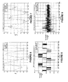
- Figure 6 illustrates the UTC-aligned gimbal angle and the reported roll angle. As shown, the time-aligned gimbal angle almost perfectly overlays the EGI measured roll angle
- Figure 7 illustrates the UTC-aligned gimbal rate and the reported roll rate. As shown, the time-aligned gimbal angle rate also almost perfectly overlays the EGI measured roll rate.
- Figure 8 illustrates an error plot of the degimbalized aircraft roll angle. A plot of zero would indicate no error, and thus the small deviation from zero indicates good test results.
- Figure 9 illustrates an error plot of the aircraft roll rate in degrees. As shown, the error was minimal for a large number of samples.
- a method and system for degimbalization of outputs from sensors mounted on a gimbal within a moving aircraft can be used to process outputs from sensors mounted on any kind of moving platform, in order to determine both sensor object and platform navigation information.
Landscapes
- Engineering & Computer Science (AREA)
- Radar, Positioning & Navigation (AREA)
- Remote Sensing (AREA)
- Automation & Control Theory (AREA)
- Physics & Mathematics (AREA)
- General Physics & Mathematics (AREA)
- Navigation (AREA)
Applications Claiming Priority (1)
| Application Number | Priority Date | Filing Date | Title |
|---|---|---|---|
| US11/441,907 US7409292B2 (en) | 2006-05-26 | 2006-05-26 | Method and system for degimbalization of vehicle navigation data |
Publications (3)
| Publication Number | Publication Date |
|---|---|
| EP1860403A2 true EP1860403A2 (de) | 2007-11-28 |
| EP1860403A3 EP1860403A3 (de) | 2009-02-18 |
| EP1860403B1 EP1860403B1 (de) | 2011-08-03 |
Family
ID=38445625
Family Applications (1)
| Application Number | Title | Priority Date | Filing Date |
|---|---|---|---|
| EP07108872A Not-in-force EP1860403B1 (de) | 2006-05-26 | 2007-05-24 | Verfahren und Vorrichtung zur Entfernung von Einflüssen der Bewegungen einer kardanischen Aufhängung auf Navigationsdaten |
Country Status (3)
| Country | Link |
|---|---|
| US (1) | US7409292B2 (de) |
| EP (1) | EP1860403B1 (de) |
| IL (1) | IL183428A0 (de) |
Cited By (1)
| Publication number | Priority date | Publication date | Assignee | Title |
|---|---|---|---|---|
| CN109073388A (zh) * | 2016-04-11 | 2018-12-21 | Hrl实验室有限责任公司 | 旋磁地理定位系统 |
Families Citing this family (11)
| Publication number | Priority date | Publication date | Assignee | Title |
|---|---|---|---|---|
| US8629836B2 (en) | 2004-04-30 | 2014-01-14 | Hillcrest Laboratories, Inc. | 3D pointing devices with orientation compensation and improved usability |
| EP1759529A4 (de) | 2004-04-30 | 2009-11-11 | Hillcrest Lab Inc | Freiraum-zeigeeinrichtungen und verfahren |
| WO2006058129A2 (en) | 2004-11-23 | 2006-06-01 | Hillcrest Laboratories, Inc. | Semantic gaming and application transformation |
| US7925439B2 (en) * | 2006-10-19 | 2011-04-12 | Topcon Positioning Systems, Inc. | Gimbaled satellite positioning system antenna |
| US8457682B2 (en) | 2008-03-04 | 2013-06-04 | Dbsd Satellite Services G.P. | Method and system for integrated satellite assistance services |
| US8296056B2 (en) * | 2009-04-20 | 2012-10-23 | Honeywell International Inc. | Enhanced vision system for precision navigation in low visibility or global positioning system (GPS) denied conditions |
| US8076622B1 (en) * | 2009-08-31 | 2011-12-13 | Rockwell Collins, Inc. | Low profile, conformal global positioning system array for artillery |
| US8816901B2 (en) * | 2012-06-01 | 2014-08-26 | Honeywell International Inc. | Calibration to improve weather radar positioning determination |
| US10181643B2 (en) * | 2015-03-05 | 2019-01-15 | The Boeing Company | Approach to improve pointing accuracy of antenna systems with offset reflector and feed configuration |
| US11118937B2 (en) | 2015-09-28 | 2021-09-14 | Hrl Laboratories, Llc | Adaptive downhole inertial measurement unit calibration method and apparatus for autonomous wellbore drilling |
| US10718198B2 (en) | 2015-09-28 | 2020-07-21 | Hrl Laboratories, Llc | Opportunistic sensor fusion algorithm for autonomous guidance while drilling |
Citations (4)
| Publication number | Priority date | Publication date | Assignee | Title |
|---|---|---|---|---|
| US3430238A (en) | 1967-07-18 | 1969-02-25 | Gen Precision Systems Inc | Apparatus for providing an accurate vertical reference in a doppler-inertial navigation system |
| US4396878A (en) | 1981-07-13 | 1983-08-02 | General Dynamics, Pomona Division | Body referenced gimballed sensor system |
| US5463402A (en) | 1993-03-30 | 1995-10-31 | Thermo King Corporation | Motion measurement system and method for airborne platform |
| US5948044A (en) | 1996-05-20 | 1999-09-07 | Harris Corporation | Hybrid GPS/inertially aided platform stabilization system |
Family Cites Families (4)
| Publication number | Priority date | Publication date | Assignee | Title |
|---|---|---|---|---|
| FR2511146B1 (fr) * | 1981-08-07 | 1986-07-25 | British Aerospace | Instrument de navigation |
| DE19756763A1 (de) * | 1997-12-19 | 1999-06-24 | Bodenseewerk Geraetetech | Suchkopf für zielverfolgende Flugkörper |
| US6859727B2 (en) * | 2003-01-08 | 2005-02-22 | Honeywell International, Inc. | Attitude change kalman filter measurement apparatus and method |
| US6863244B2 (en) * | 2003-01-24 | 2005-03-08 | The Boeing Company | Mitigation of angular acceleration effects on optical sensor data |
-
2006
- 2006-05-26 US US11/441,907 patent/US7409292B2/en not_active Expired - Fee Related
-
2007
- 2007-05-24 EP EP07108872A patent/EP1860403B1/de not_active Not-in-force
- 2007-05-27 IL IL183428A patent/IL183428A0/en not_active IP Right Cessation
Patent Citations (4)
| Publication number | Priority date | Publication date | Assignee | Title |
|---|---|---|---|---|
| US3430238A (en) | 1967-07-18 | 1969-02-25 | Gen Precision Systems Inc | Apparatus for providing an accurate vertical reference in a doppler-inertial navigation system |
| US4396878A (en) | 1981-07-13 | 1983-08-02 | General Dynamics, Pomona Division | Body referenced gimballed sensor system |
| US5463402A (en) | 1993-03-30 | 1995-10-31 | Thermo King Corporation | Motion measurement system and method for airborne platform |
| US5948044A (en) | 1996-05-20 | 1999-09-07 | Harris Corporation | Hybrid GPS/inertially aided platform stabilization system |
Cited By (1)
| Publication number | Priority date | Publication date | Assignee | Title |
|---|---|---|---|---|
| CN109073388A (zh) * | 2016-04-11 | 2018-12-21 | Hrl实验室有限责任公司 | 旋磁地理定位系统 |
Also Published As
| Publication number | Publication date |
|---|---|
| EP1860403B1 (de) | 2011-08-03 |
| US7409292B2 (en) | 2008-08-05 |
| IL183428A0 (en) | 2007-09-20 |
| US20070288165A1 (en) | 2007-12-13 |
| EP1860403A3 (de) | 2009-02-18 |
Similar Documents
| Publication | Publication Date | Title |
|---|---|---|
| EP1860403B1 (de) | Verfahren und Vorrichtung zur Entfernung von Einflüssen der Bewegungen einer kardanischen Aufhängung auf Navigationsdaten | |
| KR100761011B1 (ko) | 카메라형 태양센서를 이용한 관성항법시스템의자세보정장치 및 방법 | |
| US6463366B2 (en) | Attitude determination and alignment using electro-optical sensors and global navigation satellites | |
| US6622091B2 (en) | Method and system for calibrating an IG/GP navigational system | |
| US7328104B2 (en) | Systems and methods for improved inertial navigation | |
| CN104698486B (zh) | 一种分布式pos用数据处理计算机系统实时导航方法 | |
| Toth et al. | Performance analysis of the airborne integrated mapping system (AIMS) | |
| CN107747953B (zh) | 一种多敏感器数据与轨道信息时间同步方法 | |
| JP2008304260A (ja) | 画像処理装置 | |
| EP2603768B1 (de) | Vorrichtung und verfahren zur bestimmung der winkelorientierung von raumflugkörpern | |
| CA2720437C (en) | Systems and methods for determining heading | |
| US9243914B2 (en) | Correction of navigation position estimate based on the geometry of passively measured and estimated bearings to near earth objects (NEOS) | |
| KR100762891B1 (ko) | Los벡터 조정모델을 이용한 영상의 기하보정 방법 및 그장치 | |
| Hwang et al. | Design of a low-cost attitude determination GPS/INS integrated navigation system | |
| Smith et al. | Operational constraint analysis of terrain relative navigation for landing applications | |
| Elbahnasawy et al. | Image-assisted GNSS/INS navigation for UAV-based mobile mapping systems during GNSS outages | |
| Mouzakidou et al. | Airborne sensor fusion: Expected accuracy and behavior of a concurrent adjustment | |
| Wegmann | Image orientation by combined (A) AT with GPS and IMU | |
| US20200182590A1 (en) | Method and system of determining miss-distance | |
| Veth et al. | Tightly-coupled ins, gps, and imaging sensors for precision geolocation | |
| Theil et al. | Hybrid navigation system for spaceplanes, launch and re-entry vehicles | |
| Perry et al. | Precision directly georeferenced unmanned aerial remote sensing system: Performance evaluation | |
| Kulakova et al. | Micronavigation system to support a radar with synthetic aperture aboard a small UAV | |
| RU2812755C2 (ru) | Устройство определения координат объектов | |
| Mostafa et al. | GPS/INS integrated navigation system in support of digital image georeferencing |
Legal Events
| Date | Code | Title | Description |
|---|---|---|---|
| PUAI | Public reference made under article 153(3) epc to a published international application that has entered the european phase |
Free format text: ORIGINAL CODE: 0009012 |
|
| AK | Designated contracting states |
Kind code of ref document: A2 Designated state(s): AT BE BG CH CY CZ DE DK EE ES FI FR GB GR HU IE IS IT LI LT LU LV MC MT NL PL PT RO SE SI SK TR |
|
| AX | Request for extension of the european patent |
Extension state: AL BA HR MK YU |
|
| PUAL | Search report despatched |
Free format text: ORIGINAL CODE: 0009013 |
|
| AK | Designated contracting states |
Kind code of ref document: A3 Designated state(s): AT BE BG CH CY CZ DE DK EE ES FI FR GB GR HU IE IS IT LI LT LU LV MC MT NL PL PT RO SE SI SK TR |
|
| AX | Request for extension of the european patent |
Extension state: AL BA HR MK RS |
|
| 17P | Request for examination filed |
Effective date: 20090806 |
|
| 17Q | First examination report despatched |
Effective date: 20090903 |
|
| AKX | Designation fees paid |
Designated state(s): FR GB |
|
| REG | Reference to a national code |
Ref country code: DE Ref legal event code: 8566 |
|
| RTI1 | Title (correction) |
Free format text: METHOD OF AND APPARATUS FOR DEGIMBALIZATION OF NAVIGATION DATA |
|
| GRAP | Despatch of communication of intention to grant a patent |
Free format text: ORIGINAL CODE: EPIDOSNIGR1 |
|
| RAP1 | Party data changed (applicant data changed or rights of an application transferred) |
Owner name: HONEYWELL INTERNATIONAL INC. |
|
| GRAS | Grant fee paid |
Free format text: ORIGINAL CODE: EPIDOSNIGR3 |
|
| GRAA | (expected) grant |
Free format text: ORIGINAL CODE: 0009210 |
|
| AK | Designated contracting states |
Kind code of ref document: B1 Designated state(s): FR GB |
|
| REG | Reference to a national code |
Ref country code: GB Ref legal event code: FG4D |
|
| PLBE | No opposition filed within time limit |
Free format text: ORIGINAL CODE: 0009261 |
|
| STAA | Information on the status of an ep patent application or granted ep patent |
Free format text: STATUS: NO OPPOSITION FILED WITHIN TIME LIMIT |
|
| 26N | No opposition filed |
Effective date: 20120504 |
|
| PGFP | Annual fee paid to national office [announced via postgrant information from national office to epo] |
Ref country code: GB Payment date: 20130425 Year of fee payment: 7 |
|
| PGFP | Annual fee paid to national office [announced via postgrant information from national office to epo] |
Ref country code: FR Payment date: 20130531 Year of fee payment: 7 |
|
| GBPC | Gb: european patent ceased through non-payment of renewal fee |
Effective date: 20140524 |
|
| REG | Reference to a national code |
Ref country code: FR Ref legal event code: ST Effective date: 20150130 |
|
| PG25 | Lapsed in a contracting state [announced via postgrant information from national office to epo] |
Ref country code: FR Free format text: LAPSE BECAUSE OF NON-PAYMENT OF DUE FEES Effective date: 20140602 Ref country code: GB Free format text: LAPSE BECAUSE OF NON-PAYMENT OF DUE FEES Effective date: 20140524 |
|
| P01 | Opt-out of the competence of the unified patent court (upc) registered |
Effective date: 20230525 |