EP1860452A1 - Appareil et procédé pour mesure de résonance magnétique nucléaire d'un débit de circulation - Google Patents
Appareil et procédé pour mesure de résonance magnétique nucléaire d'un débit de circulation Download PDFInfo
- Publication number
- EP1860452A1 EP1860452A1 EP07008344A EP07008344A EP1860452A1 EP 1860452 A1 EP1860452 A1 EP 1860452A1 EP 07008344 A EP07008344 A EP 07008344A EP 07008344 A EP07008344 A EP 07008344A EP 1860452 A1 EP1860452 A1 EP 1860452A1
- Authority
- EP
- European Patent Office
- Prior art keywords
- sample
- small molecules
- vessel
- solution
- magnetic resonance
- Prior art date
- Legal status (The legal status is an assumption and is not a legal conclusion. Google has not performed a legal analysis and makes no representation as to the accuracy of the status listed.)
- Granted
Links
- 238000005481 NMR spectroscopy Methods 0.000 title claims abstract description 111
- 238000005259 measurement Methods 0.000 title claims abstract description 59
- 238000000034 method Methods 0.000 title claims abstract description 46
- 239000000523 sample Substances 0.000 claims abstract description 217
- 150000003384 small molecules Chemical class 0.000 claims abstract description 182
- 150000002605 large molecules Chemical class 0.000 claims abstract description 63
- 229920002521 macromolecule Polymers 0.000 claims abstract description 63
- 239000012488 sample solution Substances 0.000 claims abstract description 53
- 239000000243 solution Substances 0.000 claims description 111
- 238000012546 transfer Methods 0.000 claims description 90
- 239000007788 liquid Substances 0.000 claims description 46
- 239000007853 buffer solution Substances 0.000 claims description 32
- XLYOFNOQVPJJNP-UHFFFAOYSA-N water Substances O XLYOFNOQVPJJNP-UHFFFAOYSA-N 0.000 claims description 14
- 238000012544 monitoring process Methods 0.000 claims description 4
- 238000007599 discharging Methods 0.000 claims description 3
- 230000004044 response Effects 0.000 claims description 3
- 239000011796 hollow space material Substances 0.000 claims 2
- 238000002347 injection Methods 0.000 abstract description 70
- 239000007924 injection Substances 0.000 abstract description 70
- 108090000623 proteins and genes Proteins 0.000 abstract description 22
- 102000004169 proteins and genes Human genes 0.000 abstract description 21
- -1 proteins Chemical class 0.000 abstract description 2
- 238000001914 filtration Methods 0.000 abstract 1
- 238000010586 diagram Methods 0.000 description 18
- 230000014509 gene expression Effects 0.000 description 12
- 239000002904 solvent Substances 0.000 description 12
- 238000000108 ultra-filtration Methods 0.000 description 12
- 230000008569 process Effects 0.000 description 10
- 238000007865 diluting Methods 0.000 description 7
- 230000008859 change Effects 0.000 description 6
- 239000000470 constituent Substances 0.000 description 6
- 238000002372 labelling Methods 0.000 description 6
- 238000004128 high performance liquid chromatography Methods 0.000 description 5
- IJGRMHOSHXDMSA-UHFFFAOYSA-N Atomic nitrogen Chemical compound N#N IJGRMHOSHXDMSA-UHFFFAOYSA-N 0.000 description 4
- XLYOFNOQVPJJNP-ZSJDYOACSA-N Heavy water Chemical compound [2H]O[2H] XLYOFNOQVPJJNP-ZSJDYOACSA-N 0.000 description 4
- NBIIXXVUZAFLBC-UHFFFAOYSA-N Phosphoric acid Chemical compound OP(O)(O)=O NBIIXXVUZAFLBC-UHFFFAOYSA-N 0.000 description 4
- 229920006355 Tefzel Polymers 0.000 description 3
- 238000004458 analytical method Methods 0.000 description 3
- 230000008901 benefit Effects 0.000 description 3
- 230000005540 biological transmission Effects 0.000 description 3
- 238000001514 detection method Methods 0.000 description 3
- QHSJIZLJUFMIFP-UHFFFAOYSA-N ethene;1,1,2,2-tetrafluoroethene Chemical compound C=C.FC(F)=C(F)F QHSJIZLJUFMIFP-UHFFFAOYSA-N 0.000 description 3
- 230000003993 interaction Effects 0.000 description 3
- 239000000463 material Substances 0.000 description 3
- 238000003825 pressing Methods 0.000 description 3
- OKTJSMMVPCPJKN-UHFFFAOYSA-N Carbon Chemical compound [C] OKTJSMMVPCPJKN-UHFFFAOYSA-N 0.000 description 2
- 229920004459 Kel-F® PCTFE Polymers 0.000 description 2
- VYPSYNLAJGMNEJ-UHFFFAOYSA-N Silicium dioxide Chemical compound O=[Si]=O VYPSYNLAJGMNEJ-UHFFFAOYSA-N 0.000 description 2
- 229910000147 aluminium phosphate Inorganic materials 0.000 description 2
- 238000013459 approach Methods 0.000 description 2
- 239000000872 buffer Substances 0.000 description 2
- 229910052799 carbon Inorganic materials 0.000 description 2
- 238000006243 chemical reaction Methods 0.000 description 2
- UUAGAQFQZIEFAH-UHFFFAOYSA-N chlorotrifluoroethylene Chemical compound FC(F)=C(F)Cl UUAGAQFQZIEFAH-UHFFFAOYSA-N 0.000 description 2
- 230000003247 decreasing effect Effects 0.000 description 2
- 238000010790 dilution Methods 0.000 description 2
- 239000012895 dilution Substances 0.000 description 2
- 201000010099 disease Diseases 0.000 description 2
- 208000037265 diseases, disorders, signs and symptoms Diseases 0.000 description 2
- 238000011156 evaluation Methods 0.000 description 2
- 239000011521 glass Substances 0.000 description 2
- 229910052739 hydrogen Inorganic materials 0.000 description 2
- 239000001257 hydrogen Substances 0.000 description 2
- 125000004435 hydrogen atom Chemical class [H]* 0.000 description 2
- 230000004879 molecular function Effects 0.000 description 2
- 229910052757 nitrogen Inorganic materials 0.000 description 2
- 238000000655 nuclear magnetic resonance spectrum Methods 0.000 description 2
- 239000011148 porous material Substances 0.000 description 2
- 238000004448 titration Methods 0.000 description 2
- 241000588724 Escherichia coli Species 0.000 description 1
- 239000004809 Teflon Substances 0.000 description 1
- 229920006362 Teflon® Polymers 0.000 description 1
- 125000000539 amino acid group Chemical group 0.000 description 1
- 239000003708 ampul Substances 0.000 description 1
- 125000004429 atom Chemical group 0.000 description 1
- 230000003851 biochemical process Effects 0.000 description 1
- 239000003153 chemical reaction reagent Substances 0.000 description 1
- 239000003795 chemical substances by application Substances 0.000 description 1
- 150000001875 compounds Chemical class 0.000 description 1
- 230000006835 compression Effects 0.000 description 1
- 238000007906 compression Methods 0.000 description 1
- 238000011109 contamination Methods 0.000 description 1
- 239000013068 control sample Substances 0.000 description 1
- 238000010494 dissociation reaction Methods 0.000 description 1
- 230000005593 dissociations Effects 0.000 description 1
- 239000003814 drug Substances 0.000 description 1
- 238000007876 drug discovery Methods 0.000 description 1
- 230000000694 effects Effects 0.000 description 1
- 239000005350 fused silica glass Substances 0.000 description 1
- 230000001771 impaired effect Effects 0.000 description 1
- 238000004519 manufacturing process Methods 0.000 description 1
- 230000007246 mechanism Effects 0.000 description 1
- 238000000163 radioactive labelling Methods 0.000 description 1
- 230000009467 reduction Effects 0.000 description 1
- 238000012216 screening Methods 0.000 description 1
- 238000001228 spectrum Methods 0.000 description 1
- 230000003068 static effect Effects 0.000 description 1
- 239000000126 substance Substances 0.000 description 1
- 238000005406 washing Methods 0.000 description 1
Images


Classifications
-
- G—PHYSICS
- G01—MEASURING; TESTING
- G01R—MEASURING ELECTRIC VARIABLES; MEASURING MAGNETIC VARIABLES
- G01R33/00—Arrangements or instruments for measuring magnetic variables
- G01R33/20—Arrangements or instruments for measuring magnetic variables involving magnetic resonance
- G01R33/28—Details of apparatus provided for in groups G01R33/44 - G01R33/64
- G01R33/30—Sample handling arrangements, e.g. sample cells, spinning mechanisms
- G01R33/307—Sample handling arrangements, e.g. sample cells, spinning mechanisms specially adapted for moving the sample relative to the MR system, e.g. spinning mechanisms, flow cells or means for positioning the sample inside a spectrometer
-
- G—PHYSICS
- G01—MEASURING; TESTING
- G01N—INVESTIGATING OR ANALYSING MATERIALS BY DETERMINING THEIR CHEMICAL OR PHYSICAL PROPERTIES
- G01N24/00—Investigating or analyzing materials by the use of nuclear magnetic resonance, electron paramagnetic resonance or other spin effects
- G01N24/08—Investigating or analyzing materials by the use of nuclear magnetic resonance, electron paramagnetic resonance or other spin effects by using nuclear magnetic resonance
- G01N24/087—Structure determination of a chemical compound, e.g. of a biomolecule such as a protein
-
- G—PHYSICS
- G01—MEASURING; TESTING
- G01N—INVESTIGATING OR ANALYSING MATERIALS BY DETERMINING THEIR CHEMICAL OR PHYSICAL PROPERTIES
- G01N24/00—Investigating or analyzing materials by the use of nuclear magnetic resonance, electron paramagnetic resonance or other spin effects
- G01N24/08—Investigating or analyzing materials by the use of nuclear magnetic resonance, electron paramagnetic resonance or other spin effects by using nuclear magnetic resonance
- G01N24/088—Assessment or manipulation of a chemical or biochemical reaction, e.g. verification whether a chemical reaction occurred or whether a ligand binds to a receptor in drug screening or assessing reaction kinetics
-
- G—PHYSICS
- G01—MEASURING; TESTING
- G01N—INVESTIGATING OR ANALYSING MATERIALS BY DETERMINING THEIR CHEMICAL OR PHYSICAL PROPERTIES
- G01N24/00—Investigating or analyzing materials by the use of nuclear magnetic resonance, electron paramagnetic resonance or other spin effects
- G01N24/08—Investigating or analyzing materials by the use of nuclear magnetic resonance, electron paramagnetic resonance or other spin effects by using nuclear magnetic resonance
-
- G—PHYSICS
- G01—MEASURING; TESTING
- G01R—MEASURING ELECTRIC VARIABLES; MEASURING MAGNETIC VARIABLES
- G01R33/00—Arrangements or instruments for measuring magnetic variables
- G01R33/20—Arrangements or instruments for measuring magnetic variables involving magnetic resonance
- G01R33/44—Arrangements or instruments for measuring magnetic variables involving magnetic resonance using nuclear magnetic resonance [NMR]
- G01R33/46—NMR spectroscopy
- G01R33/465—NMR spectroscopy applied to biological material, e.g. in vitro testing
Definitions
- the present invention relates to an apparatus and a method for repeatedly performing a nuclear magnetic resonance measurement on a sample while changing measurement conditions.
- Molecules with functional properties in a living body such as proteins, have larger molecular weight than compounds used for medicine and include properties of large molecules.
- Binding of and interaction of a specific small molecule with a specific large molecule have been detected by use of various methods.
- a measurement using nuclear magnetic resonance (hereinafter referred to as an NMR measurement) allows information on the structure of a large molecule or information on the structure of a small molecule to be directly observed.
- an NMR measurement allows for evaluation of dissociation constants of and reaction rates of a large molecule and a small molecule based on changes in spectrum to be measured for a molecule concentration and allows for analysis of interaction of a large molecule with a small molecule based on the structures of the large molecule and small molecule.
- International Publication Number WO 01/23889 discloses a method for performing an NMR measurement on the interaction of a protein with a small molecule.
- a protein is produced by the following methods: a method for extracting from a living organism present in nature; a method for extracting from a large-scale expression system using Escherichia coli, etc. containing genes relating to production of a protein; a method using a cell-free expression system having the ability to abundantly express proteins without using a living cell; or the like.
- the labeling includes a method for labeling by combining three elements of hydrogen, carbon, and nitrogen (which are main elements of a protein), a method for labeling all elements, and a method for selective labeling to label only atoms belonging to a specific amino acid residue, and the like. Irrespective of the type of the methods, the cost for the labeling process is high.
- a nuclear magnetic resonance spectroscopy apparatus typically includes a magnet for generating a static magnetic field B 0 and a nuclear magnetic resonance probe arranged in a bore of the magnet.
- the nuclear magnetic resonance probe includes one or more coils used to apply a radio frequency magnetic field B 1 to a target sample and detect a reaction (response) of the sample to the magnetic field.
- Conventional nuclear magnetic resonance probes include a probe for measuring a stationary sample and a flow through probe.
- a sample is placed in a glass tube or ampoule (hereinafter referred to as a sample tube), and the sample tube is set at a predetermined position in an NMR apparatus so as to perform a measurement of the sample.
- a sample solution includes large molecules, small molecules for evaluation of an effect as an agent, and another reagent.
- the concentration of small molecules is, in general, measured as a parameter while the amount of large molecules in a sample solution of a predetermined amount is maintained to be constant. If a buffer solution is injected to reduce the concentration of the small molecules, the amount of the sample solution is increased. Reducing the amount of the sample solution to a predetermined amount also reduces the amount of the large molecules, resulting in a change in the measurement condition.
- Titration of small molecules in a sample tube used in the NMR measurement increases the entire volume of a sample solution, which causes a change in the concentration of large molecules present in the sample solution and a change in the solution level of the sample solution.
- the maximum concentration of small molecules in a solution to be dropped is determined based on the solubility of the small molecules.
- the solubility of a substance varies depending on the type of a solvent and the temperature of a solution. Therefore, in an NMR measurement with a change in the concentration of small molecules due to the drop, the type of the solvent and the temperature of the solution influence stability of the concentration of large molecules.
- International Publication Number WO 03/007009 discloses a flow through probe including a sample inlet port, a sample outlet port, and an internal tube extending between the sample inlet port and the sample outlet port.
- the internal tube includes a cell for holding a sample. A sample is placed into the sample inlet port, flows through the internal tube, and enters the cell. After being measured, the sample flows through the internal tube and is taken out of the probe.
- a conventional flow through probe is used in combination with a robot type sample transfer system.
- Flow through probes each combined with a different sample transfer system are available in the market, for example, from Gilson, Inc.
- samples which are each adjusted for different measurement conditions must be prepared in a plurality of vessels.
- the samples are passed through an apparatus in which the samples can be taken out of the vessels and are transferred to a flow through probe which has been already set. After the NMR measurement is completed on a sample, the sample is taken out of the probe.
- a combination of a conventional flow through probe with a sample transfer system requires that samples adjusted for a plurality of different concentration conditions be prepared.
- the number of types of solutions containing large molecules with a certain concentration is required for the number of the types of measurement conditions. This increases the cost required for the samples.
- the entire measurement needs to be repeated to evaluate functional properties of the molecules until a desired range of measurement conditions and a desired degree of changes in measurement conditions are confirmed.
- the present invention provides an apparatus and a method for a nuclear magnetic resonance measurement on a sample solution containing small molecules and large molecules such as proteins and provides an apparatus and a method for repeatedly performing a nuclear magnetic resonance measurement while controlling concentration conditions in a sample and changing a concentration of small molecules.
- a sample vessel equipped with a nuclear magnetic resonance probe is coupled to sample tubing (which includes sample transfer tubes).
- sample tubing which includes sample transfer tubes.
- the sample vessel and the sample tubing form a closed loop.
- a liquid transfer pump is provided in the closed loop so that a liquid can be circularly transferred in the closed loop.
- a part of the sample tubing is provided with a control section having means for introducing large molecules (sample), small molecules (which are to be mixed with the large molecules), and a buffer solution so as to control sample components.
- the control section includes means for selectively discharging the small molecules or the buffer solution in the case where the amount of a solution injected exceeds the entire volume of the closed loop, and controls sample components.
- the present invention allows for an NMR measurement in which a concentration of small molecules is increased or decreased so that a concentration ratio of the small molecules relative to the large molecules is changed while maintaining the amount of the large molecules to a predetermined value (maintaining a concentration of the large molecules to a constant level), the two types of molecules being present in a sample solution.
- a method for the NMR measurement on a solution containing large molecules and small molecules comprises the step of increasing or reducing a concentration of the small molecules while maintaining a concentration of the large molecules to a constant level, which makes it possible to measure a change in NMR spectrum while controlling the concentration ratio of the small molecules relative to the large molecules and maintaining the amount of the large molecules to a constant value.
- the volume of a solution in a NMR measurement vessel does not change due to a drop of a solution. Therefore, the NMR measurement can be performed while maintaining the concentration of the large molecules present in the NMR measurement vessel to a constant level irrespective of the temperature of a sample solution and solubility of the small molecules.
- Fig. 1 is a diagram showing the concept of an apparatus for a circulated flow nuclear magnetic resonance measurement on a sample solution according to a first embodiment of the present invention.
- Reference numerals 20 1 and 20 2 denote separated magnets for applying a magnetic field to a sample.
- the separated magnets 20 1 and 20 2 have bores 22 1 and 22 2 , respectively.
- Reference numeral 24 denotes a nuclear magnetic resonance probe, which is held in the bore 22 2 .
- the nuclear magnetic resonance probe 24 is provided with a vessel 10 for storing a constant amount of a sample.
- the vessel 10 is positioned in an area of a magnetic field generated by the separated magnets 20 1 and 20 2 .
- the vessel 10 is preferably made of silica glass.
- a detection coil 28 used to detect a nuclear magnetic resonance signal is disposed with an optimal positional relationship with the vessel 10.
- a transmission coil is provided to excite a sample with a predetermined high frequency signal. The transmission coil, however, is not illustrated to avoid complication of the drawing.
- Sample tube connection sections 12 and 14 are provided at the upper and lower end portions of the vessel 10, respectively.
- the vessel 10 is fluidically connected with sample transfer tubes 16 1 and 16 2 through the sample tube connection sections 12 and 14.
- the vessel 10, the sample transfer tubes 16 1 , 16 2 and a sample transfer tube 16 3 disposed in a control section 30 (which is described later) form a closed loop allowing a sample to be circulated.
- the vessel 10, the sample tube connection sections 12, 14, and connection portions of the sample transfer tubes 16 1 , 16 2 are arranged on the same axis.
- a linear portion (which is a part of the closed loop formed by connecting the vessel 10 and the sample transfer tubes 16 1 , 16 2 , 16 3 ) where the vessel 10 is coupled to the sample transfer tubes 16 1 , 16 2 is disposed between the bore 22 1 of the separated magnet 20 1 and the bore 22 2 of the separated magnet 20 2 .
- Reference numeral 26 denotes a transmitting/receiving system, which receives a signal from the detection coil 28 or transmits a signal to a transmission coil (not illustrated).
- Reference numeral 30 is the control section provided with the sample transfer tube 16 3 , which connects the sample transfer tube 16 1 and 16 2 .
- the sample transfer tube 16 3 is coupled to: a discharge valve 40; a filter section 42; a measurement unit 52 for monitoring the state of a solution such as a pH value and pressure; a solution injection unit 44 for injecting small molecules; a sample solution injection unit 46 for injecting large molecules present in a sample; a liquid injection valve 48 for injecting a buffer solution and clean water; and a liquid transfer pump 50.
- the vessel 10 and the sample transfer tube 16 1 , 16 2 , 16 3 form the closed loop so that sample components can be controlled.
- the type of the filter section 42 is not limited as long as the filter section 42 allows large molecules such as proteins to be separated from other components so that the large molecules and the other components are transferred to the outside of a wetted portion 60 coupled to the sample transfer tube 16 3 . It is preferred, however, that the filter section 42 use a film 62 having fine pores that do not allow proteins to pass therethrough and that allow other components including small molecules to pass therethrough.
- a configuration obtained by combining a disk-like ultrafiltration filter manufactured by Millipore Corporation with a disk-like filter folder is preferable. With this configuration, the size of a fine pore of the disk-like ultrafiltration filter can be selectively used based on the molecular weight of proteins present in a sample solution.
- the ultrafiltration can be carried out on components other than proteins in a preferable manner.
- a liquid filtrated by the filter 62 is discharged into a liquid reservoir 64. Since large molecules are not discharged by the filter section 42, the amount of large molecules in the closed loop is maintained to be constant.
- the solution injection unit 44 preferably electronically controls one or more pressure-driven syringe pumps.
- syringe pumps IC3100 and IC3200 manufactured by KD Scientific are fluidically connected to the sample transfer tube 16 3 .
- a solution is transferred by applying pressure while a syringe which includes a solution containing small molecules is precisely controlled.
- a solution can be injected into the closed loop in a desired manner.
- the buffer solution is placed in a syringe.
- a solution is transferred by applying pressure while the syringe is precisely controlled. Accordingly, the buffer solution can be injected into the closed loop.
- the sample solution injection unit 46 preferably electronically controls one or more pressure-driven syringe pumps.
- the syringe pumps IC3100 and IC3200 manufactured by KD Scientific are fluidically connected to the sample transfer tube 16 3 .
- a solution is transferred by applying pressure while a syringe which includes a solution containing large molecules (present in a sample) is precisely controlled.
- a solution containing large molecules can be injected into the closed loop in a desired manner.
- the liquid transfer pump 50 is used with High Performance Liquid Chromatography (HPLC).
- HPLC High Performance Liquid Chromatography
- a stepping motor or the like which allows for electronic control, is used to drive a plunger so that a solution can be transferred under constant pressure in the closed loop formed by connecting the vessel 10 and the sample transfer tubes 16 1 , 16 2 , 16 3 .
- the measurement unit 52 is an indicator for monitoring the state of a solution such as a pH value and pressure and can be used with HPLC.
- sample transfer tubes 16 1 , 16 2 , 16 3 be selected based on the properties of a sample solution. In a measurement on biological large molecules such as proteins, polyethylene ethylene ketone (PEEK), Tefzel, Kel-F, and fused silica are used in many cases.
- PEEK polyethylene ethylene ketone
- Tefzel Tefzel
- Kel-F fused silica
- the inner diameter of the sample transfer tubes is 0.5 mm to 0.65 mm; the total length of the sample transfer tubes, about 4 m; and the total volume of the vessel 10 and the sample transfer tubes, about 1000 ⁇ L.
- the liquid transfer pump 50 operates while a buffer solution is supplied through the liquid injection valve 48 so as to fill the sample transfer tubes 16 1 , 16 2 , 16 3 with the buffer solution.
- the vessel 10 is filled with the buffer solution and then the closed loop is filled with the buffer solution.
- the buffer solution the following are used: a buffer solution in which the ion concentration (pH value) is adjusted in order to maintain stability of large molecules such as proteins in the closed loop and to stably perform the NMR measurement; a phosphoric acid buffer solution; or the like.
- the discharge valve 40 is closed.
- a sample containing large molecules is placed in the sample solution injection unit 46. While the sample is controlled and a sample solution is injected, the liquid transfer pump 50 operates. It is necessary that a lock solvent required for a lock during the NMR measurement be mixed into the sample.
- a solvent such as a phosphoric acid buffer solvent which is used in a large amount during an NMR measurement on proteins
- heavy water is preferably used as a lock solvent. The concentration of the heavy water is preferably 5% to 10%.
- an appropriate buffer solvent and lock solvent are selected to perform the measurement.
- Discharge pressure of the liquid transfer pump 50 during injection of a sample solution is set to a value larger than pressure at the filter section 42 when ultrafiltration starts.
- An unnecessary buffer solution produced in the closed loop of the sample transfer tube 16 1 , 16 2 , 16 3 is discharged into the liquid reservoir 64 by the filter section 42 based on the injection of the sample solution.
- pressure indicated by the indicator (measurement unit 52) is reduced.
- the discharge pressure of the liquid transfer pump 50 is set to be reduced to a level lower than pressure required for the ultrafiltration performed by use of the filter section 42. Then, the ultrafiltration performed by using the filter section 42 is completed.
- the liquid transfer pump 50 While the pressure at the filter section 42 is lower than the pressure at the start of the ultrafiltration, the liquid transfer pump 50 operates. This allows the solution to be circulated in the closed loop formed by connecting the sample transfer tube 16 1 , 16 2 , 16 3 thereby allowing the state of the solution to be more uniform.
- a magnetic field B o generated by the magnet 20 1 and 20 2 is applied to the sample solution containing a lock solvent to allow for a magnetic field lock.
- the magnetic field lock and the magnetic field B 0 generated by the magnet 20 1 and 20 2 are adjusted to obtain the uniformity thereof.
- the magnetic field B 0 required for the NMR measurement can be uniformly maintained.
- the NMR measurement is repeatedly performed with operations for injecting and diluting small molecules. Accordingly, the NMR measurement can be performed while changing the concentration of small molecules in the sample solution.
- the sample solution is circulated by the liquid transfer pump 50 so as to form a flow of the sample solution in the closed loop formed by connecting the vessel 10, the sample transfer tubes 16 1 , 16 2 , 16 3 and the filter section 42.
- the sample solution flows in the closed loop while a solution containing small molecules is placed into the solution injection unit 44 and controlled. Then, the solution containing the small molecules is injected into the closed loop. Pressure is applied to the injected small molecules by the liquid transfer pump 50, and the small molecules are transferred together with the sample solution through the sample tubing 16 to the vessel 10 which is equipped with the nuclear magnetic resonance probe 24.
- Unnecessary solutions produced during the injection of the small molecules are a buffer solution and a solution containing small molecules included in the sample solution before the injection of the solution containing the small molecules.
- the unnecessary solutions are discharged into the liquid reservoir 64 by the filter section 42.
- pressure indicated by the indicator 52 is reduced.
- the liquid transfer pump 50 is stopped, and the pressure at the filter section 42 is reduced to a level lower than pressure required for the ultrafiltration performed by use of the filter section 42. Then, the ultrafiltration performed by using the filter section 42 is completed.
- the solution While the pressure at the filter section 42 is lower than the pressure at the start of the ultrafiltration, the solution is transferred. This allows the solution to be circulated in the closed loop formed by connecting the sample transfer tube 16 1 , 16 2 , 16 3 thereby allowing the state of the solution to be more uniform.
- a solution containing small molecules or a buffer solution is discharged by the filter section 42.
- the concentration of large molecules in the closed loop is maintained to be constant while the concentration of small molecules is increased.
- the letter V indicates the entire volume of the closed loop formed by connecting the vessel 10 equipped with the probe and the sample transfer tubes 16 1 , 16 2 , 16 3 ; ⁇ , a concentration of small molecules present in the entire volume V before all injection operations are performed; ⁇ , a concentration of small molecules to be injected; and v, the volume of small molecules for one time of injection operation.
- E(i) indicates the amount of small molecules to be discharged by the filter section for the ith time of injection operation; M(i), the amount of small molecules remaining in the closed loop after the ith time of injection operation; and ⁇ (i), the average concentration of small molecules remaining in the closed loop.
- an operation for diluting a concentration of small molecules is to inject a solvent not containing small molecules, such as a buffer solution, into the closed loop.
- a sample solution is circulated in the closed loop by use of the liquid transfer pump 50.
- a flow of the sample solution is formed in the sample transfer tube 16 3 .
- a solution not containing small molecules whose amount is set by a measurer (or user) is injected from the solution injection unit 44.
- Pressure is applied to the injected solution by the liquid transfer pump 50 and transferred together with the sample solution through the sample transfer tube 16 2 to the vessel 10 which is equipped with the nuclear magnetic resonance probe 24.
- Unnecessary solutions produced during the injection of the small molecules are discharged into the liquid reservoir 64 by the filter section 42 which discharges only a buffer solution and a solution containing small molecules present in the sample solution.
- the operation of the liquid transfer pump 50 is stopped so as to reduce the pressure of the circulation of the flow in the closed loop to a level lower than the pressure required for the ultrafiltration. Accordingly, the ultrafiltration performed by using the filter section 42 is completed. As a result, the concentration of large molecules in the closed loop is maintained to be constant while the-concentration of small molecules is reduced.
- the letter V indicates the entire volume of the closed loop formed by connecting the vessel 10 equipped with the nuclear magnetic resonance probe 24 and the sample transfer tubes 16 1 , 16 2 , and the sample transfer tube 16 3 provided in the control section 30; ⁇ (0), a concentration of small molecules present in the volume V before dilution; v, the volume of a solution not containing small molecules for one time of the injection operation; E(i), the amount of small molecules to be discharged by the filter section in the ith time of the injection operation; M(i), the amount of small molecules remaining after the ith time of the injection operation; and ⁇ (i), the average concentration of small molecules present in the closed loop.
- Combining the abovementioned operations makes it possible to increase or reduce the concentration of small molecules while maintaining the concentration of large molecules present in the sample solution to a constant level.
- the concentration of small molecules can be changed again.
- repeating the operations makes it possible to perform a series of the NMR measurement operations in which the concentration of small molecules is changed while maintaining large molecules to a constant amount and a constant concentration.
- Fig. 2 is a graph showing an example of changes in the concentration of small molecules in the case where a solution containing small molecules is injected from the solution injection unit 44 so as to increase the concentration of small molecules present in the closed loop.
- Fig. 3 is a graph showing an example of changes in the concentration of small molecules in the case where a solution not containing small molecules is injected from the solution injection unit 44 so as to reduce the concentration of small molecules present in the closed loop.
- the ordinate axis represents a concentration of small molecules present in the vessel 10 under the following conditions in which: the entire volume of the closed loop formed by connecting the vessel 10, the sample transfer tubes 16 1 , 16 2 , 16 3 and the filter section 42 is 1000 ⁇ L; a concentration of small molecules before all injection operations are performed, 0 mol/L; a concentration of small molecules injected by all the injection operations, 0.01 mol/L; and the volume of a solution injected in one time of the injection operation from the solution injection unit 44, 10 ⁇ L.
- the concentration of small molecules present in the vessel 10 is increased. Changes in the average concentration of small molecules due to injections of small molecules are expressed by expressions (1) to (6).
- the concentration ⁇ of small molecules present in the volume V before all injection operations is also 0 mol/L.
- the ordinate axis represents a concentration of small molecules present in the vessel 10 under the following conditions in which: the entire volume of the closed loop formed by connecting the vessel 10, the sample transfer tubes 16 1 , 16 2 , 16 3 and the filter section 42 is 1000 ⁇ L; a concentration of small molecules before all injection operations are performed, 0.0019 mol/L; a concentration of small molecules injected by all the injection operations, 0.00 mol/L (i.e., only a buffer solution is injected); and the volume of a solution injected in one time of the injection operation from the solution injection unit 44, 100 ⁇ L. As the number of the injection operations is increased, the concentration of small molecules present in the vessel 10 is reduced. Changes in concentration of small molecules present in the vessel 10 based on the number of injection operations are expressed by expressions (10) to (12).
- a concentration of the lock solvent present in the vessel 10 can be maintained to be constant during a series of injection operations.
- the sample is replaced with another sample to perform the next measurement.
- the following procedure be performed.
- a sample containing large molecules remaining in the sample solution injection unit 46 and small molecules remaining in the solution injection unit 44 are removed.
- the sample solution injection unit 46 and the solution injection unit 44 are washed with clean water, and clean water is poured into the units.
- a solution(s) discharged in the liquid reservoir 64 are removed.
- clean water is supplied through the liquid injection valve 48 while the liquid transfer pump 50 operates.
- the closed loop formed by connecting the sample transfer tubes 16 1 , 16 2 , 16 3 is filled with the clean water.
- the clean water in the sample solution injection unit 46 and solution injection unit 44 is pressed out of the units so that connecting sections which connects the units with the sample transfer tube 16 3 are washed.
- the clean water is circulated to some extent in the closed loop formed by connecting the sample transfer tubes 16 1 , 16 2 , 16 3 by operating the liquid transfer pump 50. After that, clean water is supplied through the liquid injection valve 48 while the discharge valve 40 is opened. In the above state, the liquid transfer pump 50 continues to operate for a short time. After that, the liquid injection valve 48 and the discharge valve 40 are closed, and the operation of the liquid transfer pump 50 is stopped. As a result, the closed loop including the vessel 10 and the sample transfer tubes 16 1 , 16 2 , 16 3 is filled with clean water. In this stage, a solution(s) discharged in the liquid reservoir 64 are removed. After that, the NMR measurement on another sample can be performed by first injecting a buffer solution. When the same buffer solution is used for the next measurement, the buffer solution may be used for washing instead of clean water. In this case, the procedure for injecting a buffer solution can be eliminated.
- Figs. 4A and 4B are diagrams showing two examples of a connection structure in which connection tubes 61 1 and 61 2 connecting the vessel 10 with the sample transfer tube 16 1 16 2 , respectively, each protrude from both end portions of the vessel 10.
- the vessel 10 includes an NMR measurement section 70 and guide sections 71 1 , 71 2 each having a wall thickness.
- the structure of the vessel 10 including those sections may be easily formed of, for example, glass in an integrated manner.
- the guide section 71 1 is made longer than the guide section 71 2
- the length of the guide section 71 1 is substantially equal to that of the guide section 71 2 .
- the structure shown in Fig. 4A is suitable, whereas for a configuration in which the nuclear magnetic resonance probe 24 supports the vessel 10 and the sample tube connection sections 12, 14, the structure shown in Fig. 4B is suitable.
- connection tubes 61 1 and 61 2 have the same outer diameter as that of the sample transfer tubes 16 1 and 16 2 .
- the preferred outer diameter ranges from 1.57 mm to 0.36 mm.
- the inner diameters of the connection tubes 61 1 , 61 2 and those of the guide sections 71 1 , 71 2 preferably range from 0.5 mm to 0.065 mm. It is necessary that a sufficient amount of a sample for the NMR measurement be stored in the NMR measurement section.
- the volume of the NMR measurement section 70 preferably ranges from 400 ⁇ L to 100 ⁇ L.
- the NMR measurement section 70 is designed to have an inner diameter sufficient to place a sample in an area of a magnetic field that is generated by the separated magnets 20 1 and 20 2 and that is suitable for the NMR measurement.
- the sample tube connection sections 12 and 14 each have a connector 65 and set screws 66 1 and 66 2 , which are compression type connectors used for HPLC.
- the connector 65 and the set screws 66 1 , 66 2 are preferably made of PEEK, PTEF, Kel-F, Tefzel, or another material which is known in a HPLC field.
- connection tubes 61 1 and 61 2 are each inserted into the connector 65 and the guide sections 71 1 and 71 2 , respectively, and fixed by the set screws 66 1 and 66 2 .
- the nuts 67 1 and 67 2 are provided to serve as loose fasteners for the connections.
- Figs. 5A and 5B are diagrams showing two examples of a connection structure in which the sample transfer tubes 16 1 and 16 2 are inserted from both end portions of the vessel 10 into narrow tubes provided in the guide sections 71 1 and 71 2 each having a wall thickness, the guide sections 71 1 and 71 2 being disposed in the vessel 10.
- the lengths of the guide sections 71 1 and 71 2 may be selected based on the structure of the nuclear magnetic resonance probe 24.
- the NMR measurement section 70 preferably ranges from 400 ⁇ L to 100 ⁇ L.
- the NMR measurement section 70 is designed to have an inner diameter sufficient to place a sample in an area of a magnetic field that is generated by the separated magnets 20 1 and 20 2 and that is suitable for the NMR measurement. It is preferred that the inner diameter of the narrow tubes of the guide sections 71 1 and 71 2 be equal to the outer diameter of the sample transfer tubes 16 1 and 16 2 connected with the guide sections 71 1 , and 71 2 , respectively. The preferred inner diameter of the narrow tubes ranges from 1.57 mm to 0.36 mm.
- Reference numerals 69 1 and 69 2 are shrink tubes. After the sample transfer tubes 16 1 and 16 2 are inserted into the guide sections 71 1 and 71 2 , the shrink tubes 69 1 and 69 2 are used to compress and fix the connections between them. For the shrink tubes 69 1 and 69 2 , a tube, which is made of Teflon (a registered trademark), Tefzel or another material known in a HPLC field and has heat shrink properties, is preferably used.
- Fig. 6 is a schematic diagram showing the configuration of a circulated flow nuclear magnetic resonance measurement apparatus according to a second embodiment of the present invention.
- the same constituent elements as those in the first embodiment shown in Fig. 1 are denoted by the same reference numerals.
- the configuration according to the second embodiment is substantially the same as the configuration according to the first embodiment except that the sample transfer tubes 16 1 and 16 2 connected with the vessel 10 through the sample tube connection sections 12 and 14, respectively, are bent at connection portions of the sample transfer tubes 16 1 and 16 2 and pass through a bore 22 2 .
- a measurement procedure in the second embodiment may be the same as that in the first embodiment.
- the second embodiment when the outer diameters of the separated magnets 20 1 and 20 2 , which are used to apply a magnetic field to a sample, are large, there is an advantage in that the total length of the sample transfer tubes 16 1 and 16 2 can be reduced.
- the structures shown in Figs. 4B and 5B are desirably used for the vessel 10.
- Fig. 7 is a diagram showing the configuration of a circulated flow nuclear magnetic resonance measurement apparatus according to a third embodiment of the present invention.
- the same constituent elements as those in the second embodiment shown in Fig. 6 are denoted by the same reference numerals.
- the configuration according to the third embodiment is substantially the same as the configuration according to the second embodiment except that the nuclear magnetic resonance probe 24 is configured to include the vessel 10, the sample tube connection sections 12, 14, and parts in the vicinity of the connection portions of the sample transfer tubes 16 1 and 16 2 connected with the vessel 10 through the sample tube connection portions 12 and 14, respectively.
- a measurement procedure in the third embodiment may be the same as that in the second embodiment.
- the vessel 10 can be firmly supported by the nuclear magnetic resonance probe 24.
- Fig. 8 is a diagram showing the configuration of a circulated flow nuclear magnetic resonance measurement apparatus according to a fourth embodiment of the present invention.
- the same constituent elements as those in the first embodiment shown in Fig. 1 are denoted by the same reference numerals.
- the configuration according to the fourth embodiment is substantially the same as the configuration according to the first embodiment except that the nuclear magnetic resonance probe 24 including the vessel 10 is provided in the bore 22 of a separated magnet 20 used to apply a magnetic field to a sample, and that a magnetic field B 0 is directed parallel to the longitudinal direction of the vessel 10.
- a measurement procedure in the fourth embodiment may be the same as that in the first embodiment.
- the fourth embodiment when the separated magnet 20 of a small size, which is used to apply a magnetic field to a sample, is used, there is an advantage in that the total length of the sample transfer tubes 16 1 and 16 2 can be reduced.
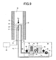
- Fig. 9 is a diagram showing the configuration of a circulated flow nuclear magnetic resonance measurement apparatus according to a fifth embodiment of the present invention.
- the same constituent elements as those in the fourth embodiment shown in Fig. 8 are denoted by the same reference numerals.
- the configuration according to the fifth embodiment is substantially the same as the configuration according to the fourth embodiment except that the nuclear magnetic resonance probe 24 is configured to include the vessel 10, the sample tube connection sections 12, 14, and parts in the vicinity of the connection portions of the sample transfer tubes 16 1 and 16 2 connected with the vessel 10 through the sample tube connection portions 12 and 14, respectively.
- a measurement procedure in the fifth embodiment may be the same as that in the fourth embodiment.
- the vessel 10 can be firmly supported by the nuclear magnetic resonance probe 24.
- Fig. 10 is a diagram showing the configuration of a circulated flow nuclear magnetic resonance measurement apparatus according to a sixth embodiment of the present invention.
- the same constituent elements as those in the fifth embodiment shown in Fig. 9 are denoted by the same reference numerals. As seen upon comparing Fig. 9 with Fig.
- the configuration according to the sixth embodiment is substantially the same as the configuration according to the fifth embodiment except that the nuclear magnetic resonance probe 24 is configured to include the vessel 10, the sample tube connection sections 12, 14, and parts in the vicinity of the connection portions of the sample transfer tubes 16 1 and 16 2 connected with the vessel 10 through the sample tube connection portions 12 and 14, respectively, and that a part of the sample transfer tube 16 1 , the vessel 10, and a part of the sample transfer tube 16 2 are arranged along a straight line.
- a measurement procedure in the sixth embodiment may be the same as that in the fifth embodiment.
- the inner diameter of the bore 22 of the magnet 20, which is used to apply a magnetic field to a sample can be reduced (compared with the structure of the fifth embodiment), which makes it possible to reduce the size of the entire apparatus.
- Fig. 11 is a diagram showing a configuration of a circulated flow nuclear magnetic resonance measurement apparatus according to a seventh embodiment of the present invention.
- the same constituent elements as those in the first embodiment shown in Fig. 1 are denoted by the same reference numerals.
- the configuration according to the seventh embodiment is substantially the same as the configuration according to the first embodiment except that an N number of the solution injection units 44 (44 1 , 44 2 , .... 44 n ) are arranged.
- solutions each containing a different type of small molecules are injected from independent syringes of the solution injection units 44 for measurement on a single sample.
- the seventh embodiment provides a method in which, while maintaining a concentration of large molecules to be measured in the vessel 10 to a constant level and maintaining a concentration of a certain type of small molecules to a constant level, concentrations of the other types of small molecules can be adjusted.
- a procedure for the measurement in the seventh embodiment may be similar to that in the first embodiment.
- a description will be made of a preferred method for maintaining a concentration of small molecules to a constant level while increasing concentrations of other types of small molecules.
- the configuration in which an N number of the solution injection units 44 (44 1 , 44 2 ,.... 44 n ) are arranged may be applied to the configurations according to the second to sixth embodiments in a similar manner to the seventh embodiment.
- the NMR measurement can be performed while each small molecule concentration in a solution containing a plurality of types of small molecules is independently changed by combining the following operations: the operation for injecting small molecules; the operation for diluting small molecules; the operation for maintaining a concentration of a certain type of small molecules to a constant level while increasing concentrations of other types of small molecules; and the operation for maintaining a concentration of a certain type of small molecules to a constant level while diluting concentrations of other types of small molecules.
- NMR measurement improves the efficiency of analysis of biochemical processes in a living organism.
- the NMR measurement is expected to be used to improve efficiencies of analysis of and screening of disease mechanisms by performing a measurement on binding affinity with disease related proteins.
Landscapes
- Physics & Mathematics (AREA)
- Chemical & Material Sciences (AREA)
- Health & Medical Sciences (AREA)
- High Energy & Nuclear Physics (AREA)
- General Physics & Mathematics (AREA)
- Life Sciences & Earth Sciences (AREA)
- General Health & Medical Sciences (AREA)
- Pathology (AREA)
- Immunology (AREA)
- Analytical Chemistry (AREA)
- Biochemistry (AREA)
- Medicinal Chemistry (AREA)
- Chemical Kinetics & Catalysis (AREA)
- Bioinformatics & Cheminformatics (AREA)
- Engineering & Computer Science (AREA)
- Condensed Matter Physics & Semiconductors (AREA)
- Crystallography & Structural Chemistry (AREA)
- Molecular Biology (AREA)
- Spectroscopy & Molecular Physics (AREA)
- Sampling And Sample Adjustment (AREA)
Applications Claiming Priority (1)
| Application Number | Priority Date | Filing Date | Title |
|---|---|---|---|
| JP2006143474A JP4825052B2 (ja) | 2006-05-24 | 2006-05-24 | 循環型フロー核磁気共鳴測定装置および測定方法 |
Publications (2)
| Publication Number | Publication Date |
|---|---|
| EP1860452A1 true EP1860452A1 (fr) | 2007-11-28 |
| EP1860452B1 EP1860452B1 (fr) | 2010-03-31 |
Family
ID=38445667
Family Applications (1)
| Application Number | Title | Priority Date | Filing Date |
|---|---|---|---|
| EP07008344A Not-in-force EP1860452B1 (fr) | 2006-05-24 | 2007-04-24 | Appareil et procédé pour mesure de résonance magnétique nucléaire d'un débit de circulation |
Country Status (4)
| Country | Link |
|---|---|
| US (1) | US7449890B2 (fr) |
| EP (1) | EP1860452B1 (fr) |
| JP (1) | JP4825052B2 (fr) |
| DE (1) | DE602007005540D1 (fr) |
Cited By (3)
| Publication number | Priority date | Publication date | Assignee | Title |
|---|---|---|---|---|
| WO2010060631A1 (fr) * | 2008-11-27 | 2010-06-03 | Bruker Biospin Gmbh | Appareil de mesure à résonance magnétique nucléaire avec tête de sonde à flux continu |
| CN111380790A (zh) * | 2018-12-29 | 2020-07-07 | 中国石油大学(北京) | 恒压条件下测量可燃冰孔隙度的系统及方法 |
| CN114485765A (zh) * | 2021-12-31 | 2022-05-13 | 安徽普氏环保装备有限公司 | 一种通用的磁分离机磁粉回收率检测系统及检测方法 |
Families Citing this family (5)
| Publication number | Priority date | Publication date | Assignee | Title |
|---|---|---|---|---|
| JP4897437B2 (ja) * | 2006-11-17 | 2012-03-14 | 株式会社日立製作所 | 低分子化合物溶液循環型フローnmr装置 |
| JP4457155B2 (ja) | 2008-02-22 | 2010-04-28 | 株式会社日立製作所 | 核磁気共鳴測定装置および核磁気共鳴測定装置を用いた測定方法 |
| JP5508081B2 (ja) | 2010-03-25 | 2014-05-28 | 株式会社神戸製鋼所 | フロースルー型nmr分析装置 |
| JP5831872B2 (ja) * | 2011-09-07 | 2015-12-09 | 国立研究開発法人産業技術総合研究所 | 核磁気共鳴を利用した反応速度解析装置 |
| US20250102479A1 (en) * | 2023-09-22 | 2025-03-27 | Thermo Finnigan Llc | Method of utilizing deuterium gas for chromatography applications, deuterium gas generator and devices for conservation thereof |
Citations (4)
| Publication number | Priority date | Publication date | Assignee | Title |
|---|---|---|---|---|
| US2721970A (en) * | 1952-01-30 | 1955-10-25 | Varian Associates | Method and means for identifying substances |
| DE2759457B1 (de) * | 1977-11-18 | 1980-04-10 | Spectrospin Ag | Spinresonanz-Spektrometer |
| WO1996013735A1 (fr) | 1994-10-26 | 1996-05-09 | Trustees Of Tufts College | Sonde d'un appareil a resonance magnetique nucleaire (rmn) comportant des bobines en tandem |
| WO2001023889A1 (fr) * | 1999-09-29 | 2001-04-05 | Smithkline Beecham Corporation | Procede relatif a l'utilisation de la resonance magnetique nucleaire (rmn) uni- et pluridimensionnelle pour identifier les composes ayant une interaction avec des biomolecules cibles |
Family Cites Families (10)
| Publication number | Priority date | Publication date | Assignee | Title |
|---|---|---|---|---|
| US5705928A (en) * | 1996-06-14 | 1998-01-06 | Varian Associates, Inc. | Sample delivery system used in chemical analysis methods which employs pressurized gas for sample conveyance |
| US6319894B1 (en) * | 1997-01-08 | 2001-11-20 | The Picower Institute For Medical Research | Complexes and combinations of fetuin with therapeutic agents |
| JP3842931B2 (ja) * | 1999-08-23 | 2006-11-08 | 日本電子株式会社 | 液体クロマトグラフ−nmr法 |
| JP2001059828A (ja) * | 1999-08-23 | 2001-03-06 | Jeol Ltd | 液体クロマトグラフ−nmr法 |
| US6380737B1 (en) | 2001-07-10 | 2002-04-30 | Varian, Inc. | Apparatus and method utilizing sample transfer to and from NMR flow probes |
| JP3918920B2 (ja) * | 2002-03-26 | 2007-05-23 | 日本電子株式会社 | Nmr測定方法 |
| DE102004002138A1 (de) * | 2004-01-15 | 2005-08-04 | Robert Bosch Gmbh | Verfahren und Vorrichtung zur Erfassung von physikalischen Eigenschaften eines Gases oder eines Gasgemisches im Bereich eines Hochfrequenz-Resonators |
| JP4403807B2 (ja) * | 2004-01-22 | 2010-01-27 | 東ソー株式会社 | 示差屈折計を備えた液体クロマトグラフ装置 |
| US7157699B2 (en) * | 2004-03-29 | 2007-01-02 | Purdue Research Foundation | Multiplexed mass spectrometer |
| JP2006068689A (ja) * | 2004-09-03 | 2006-03-16 | Toyobo Co Ltd | 中空糸膜束の乾燥方法 |
-
2006
- 2006-05-24 JP JP2006143474A patent/JP4825052B2/ja not_active Expired - Fee Related
-
2007
- 2007-04-24 DE DE602007005540T patent/DE602007005540D1/de active Active
- 2007-04-24 EP EP07008344A patent/EP1860452B1/fr not_active Not-in-force
- 2007-05-09 US US11/798,015 patent/US7449890B2/en not_active Expired - Fee Related
Patent Citations (4)
| Publication number | Priority date | Publication date | Assignee | Title |
|---|---|---|---|---|
| US2721970A (en) * | 1952-01-30 | 1955-10-25 | Varian Associates | Method and means for identifying substances |
| DE2759457B1 (de) * | 1977-11-18 | 1980-04-10 | Spectrospin Ag | Spinresonanz-Spektrometer |
| WO1996013735A1 (fr) | 1994-10-26 | 1996-05-09 | Trustees Of Tufts College | Sonde d'un appareil a resonance magnetique nucleaire (rmn) comportant des bobines en tandem |
| WO2001023889A1 (fr) * | 1999-09-29 | 2001-04-05 | Smithkline Beecham Corporation | Procede relatif a l'utilisation de la resonance magnetique nucleaire (rmn) uni- et pluridimensionnelle pour identifier les composes ayant une interaction avec des biomolecules cibles |
Non-Patent Citations (2)
| Title |
|---|
| O'LEARY D J ET AL: "Indirect monitoring of carbon-13 metabolism with NMR: Analysis of perfusate with a closed-loop flow system", MAGNETIC RESONANCE IN MEDICINE 1987 UNITED STATES, vol. 5, no. 6, 1987, pages 572 - 577, XP002449637, ISSN: 0740-3194 * |
| O'LEARY: "Indirect monitoring of carbon-13 metabolism with NMR: Analysis of perfusate with a closed-loop flow system", MAGNETIC RESONANCE IN MEDICINE, vol. 5, no. 6, 1987, pages 572 - 577, XP002449637, DOI: doi:10.1002/mrm.1910050608 |
Cited By (4)
| Publication number | Priority date | Publication date | Assignee | Title |
|---|---|---|---|---|
| WO2010060631A1 (fr) * | 2008-11-27 | 2010-06-03 | Bruker Biospin Gmbh | Appareil de mesure à résonance magnétique nucléaire avec tête de sonde à flux continu |
| US8766631B2 (en) | 2008-11-27 | 2014-07-01 | Bruker Biospin Gmbh | NMR measurement apparatus with flow-through probehead |
| CN111380790A (zh) * | 2018-12-29 | 2020-07-07 | 中国石油大学(北京) | 恒压条件下测量可燃冰孔隙度的系统及方法 |
| CN114485765A (zh) * | 2021-12-31 | 2022-05-13 | 安徽普氏环保装备有限公司 | 一种通用的磁分离机磁粉回收率检测系统及检测方法 |
Also Published As
| Publication number | Publication date |
|---|---|
| JP4825052B2 (ja) | 2011-11-30 |
| DE602007005540D1 (de) | 2010-05-12 |
| US20070273381A1 (en) | 2007-11-29 |
| EP1860452B1 (fr) | 2010-03-31 |
| JP2007315826A (ja) | 2007-12-06 |
| US7449890B2 (en) | 2008-11-11 |
Similar Documents
| Publication | Publication Date | Title |
|---|---|---|
| EP1860452B1 (fr) | Appareil et procédé pour mesure de résonance magnétique nucléaire d'un débit de circulation | |
| US7169599B2 (en) | Fluid interface for bioprocessor systems | |
| US4177677A (en) | Sample supply to automatic analyzers | |
| US20100021880A1 (en) | Automated Macromolecule Sample Preparation System | |
| Hilty et al. | Spectrally Resolved Magnetic Resonance Imaging of the Xenon Biosensor | |
| US20140262990A1 (en) | Medical fluid sensors and related systems and methods | |
| EP0813071A1 (fr) | Système pour la délivrance d'échantillons utilisé dans des méthodes d'analyse chimique lequel employe du gaz pressurisé comme moyen de transport | |
| EP3896457A1 (fr) | Vérification automatique et ré-étalonnage d'un volume transporté de pompe | |
| WO2021207297A1 (fr) | Réacteur à membrane à hyperpolarisation par parahydrogène | |
| Yang et al. | Development of a fully automated workstation for conducting routine SABRE hyperpolarization | |
| US7492157B2 (en) | Apparatus of nuclear magnetic resonance measurement by using circulation flow for sample condition control | |
| EP2249164A1 (fr) | Procédé de traitement d'un fluide biologique pour la détermination d'un analyte | |
| WO2004112942A1 (fr) | Systeme d'electrophorese capillaire fixe | |
| US5849592A (en) | Carrierless sequential injection analysis | |
| US7898256B2 (en) | Nuclear magnetic resonance measurement apparatus and measuring method using the same | |
| US20250383325A1 (en) | Automated sample handling system for liquid chromatography-mass spectrometry | |
| CN116223554A (zh) | 一种用于dDNP的探针分子多通道代谢示踪检测的装置和方法 | |
| WO2002101381A1 (fr) | Chromatographe liquide et systeme d'analyse | |
| CN115516319B (zh) | 自动分析装置的控制方法 | |
| US20230070852A1 (en) | Coupling device for an nmr flow cell | |
| EP3832333A1 (fr) | Procédé et dispositif de fourniture d'un matériau échantillon liquide à une configuration de spectromètre | |
| Linhares et al. | In vivo sampling using loop microdialysis probes coupled to a liquid chromatograph | |
| US20110274585A1 (en) | Mixing cartridge and sample testing device | |
| CA3202423A1 (fr) | Appareil et procede de quantification d'adn environnemental sans preparation d'echantillon | |
| CN121513982A (zh) | 一种液体流速控制方法以及液体流速控制设备 |
Legal Events
| Date | Code | Title | Description |
|---|---|---|---|
| PUAI | Public reference made under article 153(3) epc to a published international application that has entered the european phase |
Free format text: ORIGINAL CODE: 0009012 |
|
| AK | Designated contracting states |
Kind code of ref document: A1 Designated state(s): AT BE BG CH CY CZ DE DK EE ES FI FR GB GR HU IE IS IT LI LT LU LV MC MT NL PL PT RO SE SI SK TR |
|
| AX | Request for extension of the european patent |
Extension state: AL BA HR MK YU |
|
| 17P | Request for examination filed |
Effective date: 20080331 |
|
| 17Q | First examination report despatched |
Effective date: 20080508 |
|
| AKX | Designation fees paid |
Designated state(s): DE FR GB |
|
| GRAP | Despatch of communication of intention to grant a patent |
Free format text: ORIGINAL CODE: EPIDOSNIGR1 |
|
| GRAS | Grant fee paid |
Free format text: ORIGINAL CODE: EPIDOSNIGR3 |
|
| GRAA | (expected) grant |
Free format text: ORIGINAL CODE: 0009210 |
|
| AK | Designated contracting states |
Kind code of ref document: B1 Designated state(s): DE FR GB |
|
| REG | Reference to a national code |
Ref country code: GB Ref legal event code: FG4D |
|
| REF | Corresponds to: |
Ref document number: 602007005540 Country of ref document: DE Date of ref document: 20100512 Kind code of ref document: P |
|
| PLBE | No opposition filed within time limit |
Free format text: ORIGINAL CODE: 0009261 |
|
| STAA | Information on the status of an ep patent application or granted ep patent |
Free format text: STATUS: NO OPPOSITION FILED WITHIN TIME LIMIT |
|
| 26N | No opposition filed |
Effective date: 20110104 |
|
| PGFP | Annual fee paid to national office [announced via postgrant information from national office to epo] |
Ref country code: GB Payment date: 20140423 Year of fee payment: 8 |
|
| PGFP | Annual fee paid to national office [announced via postgrant information from national office to epo] |
Ref country code: FR Payment date: 20140409 Year of fee payment: 8 Ref country code: DE Payment date: 20140430 Year of fee payment: 8 |
|
| REG | Reference to a national code |
Ref country code: DE Ref legal event code: R119 Ref document number: 602007005540 Country of ref document: DE |
|
| GBPC | Gb: european patent ceased through non-payment of renewal fee |
Effective date: 20150424 |
|
| PG25 | Lapsed in a contracting state [announced via postgrant information from national office to epo] |
Ref country code: DE Free format text: LAPSE BECAUSE OF NON-PAYMENT OF DUE FEES Effective date: 20151103 Ref country code: GB Free format text: LAPSE BECAUSE OF NON-PAYMENT OF DUE FEES Effective date: 20150424 |
|
| REG | Reference to a national code |
Ref country code: FR Ref legal event code: ST Effective date: 20151231 |
|
| PG25 | Lapsed in a contracting state [announced via postgrant information from national office to epo] |
Ref country code: FR Free format text: LAPSE BECAUSE OF NON-PAYMENT OF DUE FEES Effective date: 20150430 |