EP1860470A1 - Panneau de guide lumineux et unité de rétroéclairage l'utilisant - Google Patents
Panneau de guide lumineux et unité de rétroéclairage l'utilisant Download PDFInfo
- Publication number
- EP1860470A1 EP1860470A1 EP07108829A EP07108829A EP1860470A1 EP 1860470 A1 EP1860470 A1 EP 1860470A1 EP 07108829 A EP07108829 A EP 07108829A EP 07108829 A EP07108829 A EP 07108829A EP 1860470 A1 EP1860470 A1 EP 1860470A1
- Authority
- EP
- European Patent Office
- Prior art keywords
- light guide
- guide panel
- prism
- backlight unit
- light rays
- Prior art date
- Legal status (The legal status is an assumption and is not a legal conclusion. Google has not performed a legal analysis and makes no representation as to the accuracy of the status listed.)
- Withdrawn
Links
Images




Classifications
-
- G—PHYSICS
- G02—OPTICS
- G02B—OPTICAL ELEMENTS, SYSTEMS OR APPARATUS
- G02B6/00—Light guides; Structural details of arrangements comprising light guides and other optical elements, e.g. couplings
- G02B6/0001—Light guides; Structural details of arrangements comprising light guides and other optical elements, e.g. couplings specially adapted for lighting devices or systems
- G02B6/0011—Light guides; Structural details of arrangements comprising light guides and other optical elements, e.g. couplings specially adapted for lighting devices or systems the light guides being planar or of plate-like form
- G02B6/0033—Means for improving the coupling-out of light from the light guide
- G02B6/0035—Means for improving the coupling-out of light from the light guide provided on the surface of the light guide or in the bulk of it
- G02B6/0036—2-D arrangement of prisms, protrusions, indentations or roughened surfaces
-
- G—PHYSICS
- G02—OPTICS
- G02F—OPTICAL DEVICES OR ARRANGEMENTS FOR THE CONTROL OF LIGHT BY MODIFICATION OF THE OPTICAL PROPERTIES OF THE MEDIA OF THE ELEMENTS INVOLVED THEREIN; NON-LINEAR OPTICS; FREQUENCY-CHANGING OF LIGHT; OPTICAL LOGIC ELEMENTS; OPTICAL ANALOGUE/DIGITAL CONVERTERS
- G02F1/00—Devices or arrangements for the control of the intensity, colour, phase, polarisation or direction of light arriving from an independent light source, e.g. switching, gating or modulating; Non-linear optics
- G02F1/01—Devices or arrangements for the control of the intensity, colour, phase, polarisation or direction of light arriving from an independent light source, e.g. switching, gating or modulating; Non-linear optics for the control of the intensity, phase, polarisation or colour
- G02F1/13—Devices or arrangements for the control of the intensity, colour, phase, polarisation or direction of light arriving from an independent light source, e.g. switching, gating or modulating; Non-linear optics for the control of the intensity, phase, polarisation or colour based on liquid crystals, e.g. single liquid crystal display cells
- G02F1/133—Constructional arrangements; Operation of liquid crystal cells; Circuit arrangements
- G02F1/1333—Constructional arrangements; Manufacturing methods
- G02F1/1335—Structural association of cells with optical devices, e.g. polarisers or reflectors
-
- G—PHYSICS
- G02—OPTICS
- G02B—OPTICAL ELEMENTS, SYSTEMS OR APPARATUS
- G02B6/00—Light guides; Structural details of arrangements comprising light guides and other optical elements, e.g. couplings
- G02B6/0001—Light guides; Structural details of arrangements comprising light guides and other optical elements, e.g. couplings specially adapted for lighting devices or systems
- G02B6/0011—Light guides; Structural details of arrangements comprising light guides and other optical elements, e.g. couplings specially adapted for lighting devices or systems the light guides being planar or of plate-like form
- G02B6/0033—Means for improving the coupling-out of light from the light guide
- G02B6/0035—Means for improving the coupling-out of light from the light guide provided on the surface of the light guide or in the bulk of it
- G02B6/0038—Linear indentations or grooves, e.g. arc-shaped grooves or meandering grooves, extending over the full length or width of the light guide
-
- G—PHYSICS
- G02—OPTICS
- G02B—OPTICAL ELEMENTS, SYSTEMS OR APPARATUS
- G02B6/00—Light guides; Structural details of arrangements comprising light guides and other optical elements, e.g. couplings
- G02B6/0001—Light guides; Structural details of arrangements comprising light guides and other optical elements, e.g. couplings specially adapted for lighting devices or systems
- G02B6/0011—Light guides; Structural details of arrangements comprising light guides and other optical elements, e.g. couplings specially adapted for lighting devices or systems the light guides being planar or of plate-like form
- G02B6/0033—Means for improving the coupling-out of light from the light guide
- G02B6/005—Means for improving the coupling-out of light from the light guide provided by one optical element, or plurality thereof, placed on the light output side of the light guide
- G02B6/0053—Prismatic sheet or layer; Brightness enhancement element, sheet or layer
Definitions
- the present invention relates to a backlight unit (BLU) for a flat display device, and more particularly to a backlight unit using a light guide panel (LGP).
- BLU backlight unit
- LGP light guide panel
- a liquid crystal display as a representative of flat display devices, does not generate light by itself.
- the LCD requires external illumination, such as a backlight unit, for providing uniform illumination over the entire surface thereof.
- FIG. 1 is a side view illustrating a conventional backlight unit.
- the backlight unit 100 includes a reflection panel 140, a light source 130, a light guide panel 110, first and second diffusion panels 150 and 180, and first and second prism sheets 160 and 170.
- the Z-axis represents the illumination direction of the backlight unit 100, the direction normal to the upper surface 114 of the light guide panel 110;
- the X-axis represents the advancing direction of the light emitted from the light source 130;
- the Y-axis represents the direction perpendicular to the X-axis and the Z-axis.
- the light guide panel 110 has upper and lower surface 114 and 112, which are opposite from each other, and first and second side surfaces 116 and 118, which are opposite from each other.
- the light source 130 faces and emits light rays toward the first side surface 116 of the light guide panel 110.
- the light guide panel 110 guides the light rays introduced from the first side surface 116 toward the second side surface 118 through internal reflection between the upper and lower surfaces 114 and 112.
- the light guide panel 110 has a plurality of dot patterns 120 which are uniformly formed on the lower surface 112 thereof. Each dot pattern 120 is in the shape of a hemispherical groove, and reflects and diffuses the incident rays.
- each dot pattern 120 prevents total internal reflection condition on an interface between the light guide panel 110 and external air such that the light rays reflected and diffused by the dot pattern 120 can be transmitted through the upper surface 114 of the light guide panel 110.
- low brightness is obtained when a viewing angle is 0° and higher brightness is obtained as a viewing angle increases.
- the viewing angle of 0° means that an observer views on the Z-axis.
- the reflection panel 140 is located such that the upper surface thereof faces the lower surface 112 of the light guide panel 110.
- the reflection panel 140 reflects the light rays transmitted through the lower surface 112 of the light guide panel 110 and redirects the reflected light rays into the light guide panel 110.
- the first diffusion panel 150 is located such that the lower surface thereof faces the upper surface 114 of the light guide panel 110.
- the first diffusion panel 150 scatters and transmits inputted light rays.
- the first and second diffusion panels 150 and 180 scatter incident light rays, and function to uniformize the brightness distribution which is concentrated over high viewing angles.
- the first prism sheet 160 is located such that the lower surface thereof faces the upper surface of the first diffusion panel 150.
- the first prism sheet 160 includes a base plate 162 and a plurality of prism projections 164, which project from the upper surface of the base plate 162 and extend parallel to one another. At this time, the prism projections 164 are arranged along the X-axis, along the direction normal to the first side surface 116 of the light guide panel 110.
- the first prism sheet 160 concentrates and transmits inputted light rays through the vertical planes thereof, in the Y-Z planes.
- Each of the first and second prism sheets 160 and 170 provides brightness enhancement at low viewing angles.
- the second prism sheet 170 is located such that the lower surface thereof faces the upper surface of the first prism sheet 160.
- the second prism sheet 170 includes a base plate 172 and a plurality of prism projections 174 which project from the upper surface of the base plate 172 and extend parallel to one another. At this time, the prism projections 174 are arranged along the Y-axis, along the direction perpendicular to the normal of the first side surface 116 of the light guide panel 110.
- the second prism sheet 170 concentrates and transmits inputted light rays through the vertical planes thereof, in the X-Z planes.
- the second diffusion panel 180 is located such that the lower surface thereof faces the upper surface of the second prism sheet 170.
- the second diffusion panel 180 scatters and transmits inputted light rays.
- the conventional backlight unit 100 constructed described above, however, has the following problems.
- the manufacturing cost and the thickness of the backlight unit 100 are high.
- an optical insertion loss occurs in the conventional backlight unit 100, as the rays emitted through the upper surface 114 of the light guide panel 110 are transmitted through the first and second prism sheets 160 and 170. Such an optical insertion loss contributes to the deterioration of the optical efficiency of the conventional backlight unit 100.
- the present invention has been made to solve the above-mentioned problems occurring in the prior art and provides additional advantages, by providing a light guide panel and a backlight unit using the same which can improve optical efficiency and lower manufacturing cost.
- One aspect of the present invention provides a light guide panel having upper and lower surfaces, which are opposite from each other, and first and second side surfaces, which are opposite from each other, for guiding light rays inputted therein through the first side surface toward the second side surface through internal reflection between the upper and lower surfaces.
- the light guide panel includes a plurality of dot patterns formed on the lower surface to reflect and diffuse incident light rays; first prism projections that are formed on the upper surface and that are parallel to one another, to transmit and concentrate light rays reflected by the dot patterns; and second prism projections that are formed on the upper surface to cross the first prism projections and that are parallel to one another, to transmit and concentrate light rays reflected by the dot patterns.
- a backlight unit including a light guide panel having upper and lower surfaces, which are opposite from each other; first and second side surfaces, which are opposite from each other, to guide light rays inputted therein through the first side surface toward the second side surface through internal reflection between the upper and lower surfaces; and a light source facing the first side surface of the light guide panel to output light rays toward the first side surface.
- the light guide panel includes a plurality of dot patterns formed on the lower surface to reflect and diffuse incident light rays; and a prism pattern formed on the upper surface to have prism projections in the shape of a letter X, for transmitting and concentrating light rays reflected by the dot patterns.
- FIG. 2 is a side view illustrating a backlight unit in accordance with a first embodiment of the present invention.
- the backlight unit 200 includes a reflection panel 250, a light source 240, a light guide panel 210, a diffusion panel 260, and a prism sheet 270.
- the Z-axis represents the illumination direction of the backlight unit 200, the direction normal to the upper surface 214 of the light guide panel 210;
- the X-axis represents the advancing direction of the light emitted from the light source 240;
- the Y-axis represents the direction perpendicular to the X-axis and the Z-axis.
- the light guide panel 210 has upper and lower surface 214 and 212, which are opposite from each other, and first and second side surfaces 216 and 218, which are opposite from each other.
- the light source 240 faces the first side surface 216 of the light guide panel 210, and emits light rays toward the first side surface 216.
- the light source 240 may be, for example, a light emitting diode (LED), a laser diode (LD), or a lamp, or any other device that emits light.
- the light guide panel 210 guides the light rays introduced from the first side surface 216 toward the second side surface 218 through internal reflection between the upper and lower surfaces 214 and 212.
- the light guide panel 210 also has a plurality of dot patterns 220 that are formed on or near the lower surface 212 of the panel 210.
- Each dot pattern 220 may have various sectional shapes, such as, for example, circular, elliptical, quadrangular, or rhombic shape.
- the dot patterns 220 may be formed on the lower surface 212 of the light guide panel 210 in the form of intaglios, that is, grooves, or embossments that is, protrusions.
- each dot pattern 220 of the present invention is in the shape of a hemispherical groove.
- each dot pattern 220 may also be a diffuse reflection pattern such as scratches, as the occasion demands.
- the respective dot patterns 220 may be formed by integrating the dot patterns 220 into the light guide panel 210.
- the dot patterns 220 may alternatively formed separately from the light guide panel 210, in the form of protrusions, and then are attached to the lower surface 212 of the light guide panel 210.
- FIGs. 3a and 3b are cross-sectional views illustrating dot patterns having circular sectional shapes.
- FIG. 3a illustrates a dot pattern 220a having a circular sectional shape, formed on the lower surface 212 of the light guide plate 210 through engraving.
- FIG. 3b illustrates a dot pattern 220b having a circular sectional shape, formed on the lower surface 212 of the light guide plate 210 through embossing.
- each dot pattern 220 reflects and diffuses the incident light rays.
- each dot pattern 220 prevents a total internal reflection of light rays on the interface of the light guide panel 210 and external air, such that the light rays reflected and diffused by the dot pattern 220 are transmitted through the upper surface 214 of the light guide panel 210.
- the intensity of the light rays is attenuated.
- Such attenuation causes a gradual decrease in the light appearing on the upper surface 214 of the light guide panel 210 from the first side surface 216 toward the second side surface 218, and causes a non-uniform brightness distribution on the light guide panel 210.
- the non-uniform brightness distribution may be corrected by gradually increasing the density of the dot patterns 220 from the first side surface 216 toward the second side surface 218.
- the density of the dot patterns 220 may be defined as the area occupied by the dot patterns 220 per unit area of the light guide panel.
- the change in the density of the dot patterns 220 may be achieved by changing the number of the dot patterns 220 per unit area of the light guide panel 210, changing the size of the dot patterns 220 along the direction of the first side surface 216 to the second side surface 218 to change the area of the light guide panel 210 occupied by the dot patterns 220, or a combination thereof.
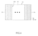
- FIG. 4 is a view illustrating the distribution of dot patterns having varying densities.
- the dot patterns 220c which are formed on the lower surface 212 of the light guide panel 210, have the same shape and size, and the number of dot patterns 220c per a unit area gradually increases from the first side surface 216 toward the second side surface 218.
- the light guide panel 210 has a prism pattern 230.
- the prism pattern 230 is formed on the upper surface 214 of the light guide panel 210 and has prism projections disposed in the shape of the letter X.
- the prism pattern 230 has the design of a quadrangle having crossed stripes, preferably, the design of a rhombus having crossed stripes.
- the prism pattern 230 transmits and concentrates the light rays which are reflected and diffused by the dot patterns 220.
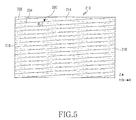
- FIG. 5 is a plan view illustrating the upper surface 214 of the light guide panel 210.
- the prism pattern 230 formed on the upper surface 214 of the light guide panel 210 is composed of first prism projections 232 and second prism projections 234. As shown in FIG. 5, each of the lines 232 represents a first prism projection 232, and each of lines 234 represents a second prism projection 234.
- the first prism projections 232 are parallel to one another, and have a uniform pitch.
- the first prism projections 232 transmit and concentrate the light rays reflected by the dot patterns 220 through the vertical planes thereof, through the vertical sectional planes perpendicular to the lengthwise direction of the first prism projections 232.
- the second prism projections 234 are formed such that the second prism projections 234 cross the first prism projections 232.
- the second prism projections 234 are parallel to one another, and have a uniform pitch.
- the second prism projections 234 transmit and concentrate the light rays reflected and diffused by the dot patterns 220 through the vertical planes thereof, through the vertical sectional planes perpendicular to the lengthwise direction of the second prism projections 234.
- the first and second prism projections 232 and 234 may project from the upper surface 214 of the light guide panel 210.
- Each of the first and second prism projections 232 and 234 has a pitch no greater than 0.3 mm.
- the angle ⁇ 1 between the first and second prism projections 232 and 234 is in the range of 2 ⁇ 40°, whereas the angle between the X-axis and each of the prism projections 232 and 234 is in the range of 1 ⁇ 20°. If the prism projections are parallel to the X-axis, the light rays inside the light guide panel 210 may not be transmitted through the prism projections. Instead, the light ray may flow along the prism projections resulting in brightness deterioration.
- the prism projections are perpendicular to the X-axis, the light rays in the light guide panel 210 may be attenuated quickly by the prism projections, and the amount of light rays which reach the second side surface 218 of the light guide panel 210 may decrease. In such a case brightness deterioration may also occur.
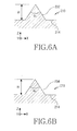
- FIG. 6 is views illustrating the first and second prism projections 232 and 234.
- FIG. 6a is a cross-sectional view of the first prism projections 232
- FIG. 6b is a cross-sectional view of the second prism projections 234.
- the first and second prism projections 232 and 234 have the same sectional shape.
- Each of the first and second prism projections 232 and 234 has a prism angle ⁇ 2 in the range of 60 ⁇ 120° and a height H in the range of 2 ⁇ 20 ⁇ m.
- Each of the first and second prism projections 232 and 234, for example, has the sectional shape of an isosceles triangle.
- each of the first and second prism projections 232 and 234 shown in FIG. 6 has a pointed contour the first and second prism projections 232 and 234 may also have a curved contour with a predetermined radius.
- the reflection panel 250 is located such that the upper surface thereof faces the lower surface 212 of the light guide panel 210.
- the reflection panel 250 reflects the light rays transmitted through the lower surface 212 of the light guide panel 210 and redirects the light rays into the light guide panel 210.
- the reflection panel 250 has reflectance approaching to 100%, another reflectance panel with lower reflectance may be used as needed.
- the backlight unit 200 may also be used for bidirectional illumination. In the latter case, the reflectance of the reflection panel 250 may be set at 50 ⁇ 80%, and another diffusion panel and another prism sheet can be sequentially arranged below the reflection panel 250.
- the diffusion panel 260 is disposed such that the lower surface thereof faces the upper surface 214 of the light guide panel 210.
- the diffusion panel 260 scatters and transmits inputted light rays, and uniformize the brightness distribution, which is concentrated over high viewing angles.
- the prism sheet 270 is located such that the lower surface thereof faces the upper surface of the diffusion panel 260.
- the prism sheet 270 includes a base plate 272 and a plurality of third prism projections 274 that project from the upper surface of the base plate 272 and that are parallel to one another.
- the third prism projections 274 can be arranged along various directions. For example, the third prism projections 274 are arranged along the X-axis, in the direction normal to the first side surface 216 of the light guide panel 210.
- the prism sheet 270 concentrates and transmits the light rays inputted from the diffusion panel 260.
- the prism sheet 270 provides brightness enhancement at low viewing angles
- the end portion of the light guide panel which is adjacent to the first side surface facing the light source, may be integrally formed with an inclined projection, or, alternatively, the light guide panel may have a slope on one of the upper and lower surfaces thereof. Such configuration improves optical coupling efficiency of the light guide panel with the light source.
- FIGs. 7a and 7b are views schematically illustrating various shapes of light guide panels.
- FIG. 7a illustrates a light guide panel 210a having a slope on one surface thereof.
- the light guide panel 210a has upper and lower surfaces 214a and 212a which are opposite from each other and first and second side surfaces 216a and 218a which are opposite from each other.
- the light guide panel 210a has a plurality of dot patterns 220 that are formed on the lower surface 212a thereof, and a prism pattern 230 that is formed on the upper surface 214a thereof.
- the lower surface 212a is sloped with respect to the upper surface 214a, and the thickness of the light guide panel 210a decreases gradually from the first side surface 216a toward the second side surface 218a.
- FIG. 7b illustrates a light guide panel 210b having an end portion that is integrally formed with an inclined projection.
- the light guide panel 210b has upper and lower surfaces 214b and 212b, which are opposite from each other, and first and second side surfaces 216b and 218b, which are opposite from each other. Further, the light guide panel 210b has a plurality of dot patterns 220, which are formed on the lower surface 212b thereof, and a prism pattern 230, which is formed on the upper surface 214b thereof.
- the inclined projection is integrally formed on the upper surface of the end portion of the light guide panel 210b which is adjacent to the first side surface 216b.
- the inclined projection inclines upward toward the first side surface 216b of the light guide panel 210b so that the thickness of the inclined projection gradually decreases from the first side surface 216b toward the second side surface 218b.
- the backlight unit according to the present invention can be used for bidirectional illumination.
- FIG. 8 is a side view illustrating a backlight unit in accordance with the second aspect of the present invention.
- the backlight unit 200a includes all the component parts of the backlight unit 200 shown in FIG. 2, and it further includes another diffusion panel and another prism sheet. Therefore, the same reference numerals will be used to refer to the same component parts, and detailed descriptions thereof will be omitted.
- the backlight unit 200a includes a reflection panel 250a, a light source 240, a light guide panel 210, first and second diffusion panels 260 and 260a, and first and second prism sheets 270 and 270a.
- the reflection panel 250a is located such that the upper surface thereof faces the lower surface 212 of the light guide panel 210, and has reflectance of 50 ⁇ 80%.
- the reflection panel 250a reflects one part of the light rays transmitted through the lower surface 212 of the light guide panel 210 so that the corresponding part of the light rays is redirected into the light guide panel 210, and transmits the other part of the light rays transmitted through the lower surface 212 of the light guide panel 210.
- the second diffusion panel 260a is located such that the upper surface thereof faces the lower surface 212 of the light guide panel 210.
- the second diffusion panel 260a scatters and transmits inputted light rays, and uniformizes the brightness distribution, which is concentrated over high viewing angles.
- the second prism sheet 270a is located such that the upper surface thereof faces the lower surface of the second diffusion panel 260a.
- the second prism sheet 270a includes a base plate 272a and a plurality of fourth prism projections 274a, which project from the upper surface of the base plate 272a and are parallel to one another.
- the fourth prism projections 274a may be arranged along various directions.
- the fourth prism projections 274a are arranged along the X-axis, in the direction normal to the first side surface 216 of the light guide panel 210.
- the second prism sheet 270a concentrates and transmits the light rays inputted from the second diffusion panel 260a.
- the second prism sheet 270a provides brightness enhancement at low viewing angles
- one advantage of the light guide panel and the backlight unit according to the present invention is that less number of the prism sheets are required in the present invention, as the present invention has a prism pattern formed on the upper surface of the light guide panel and as the present invention has prism projections crossing one another in the shape of the letter X.
- the thickness of the backlight unit may be reduced significantly, the optical insertion loss may be reduced, and the optical efficiency and entire brightness can be elevated.
- the cost of manufacturing the light guide panel or the backlight may be lowered.
- the light guide panel and the backlight unit according to the present invention has smaller thickness compared to the conventional art, the light guide panel and the backlight unit can be easily adapted for a mobile terminal.
Landscapes
- Physics & Mathematics (AREA)
- General Physics & Mathematics (AREA)
- Optics & Photonics (AREA)
- Nonlinear Science (AREA)
- Mathematical Physics (AREA)
- Chemical & Material Sciences (AREA)
- Crystallography & Structural Chemistry (AREA)
- Planar Illumination Modules (AREA)
Applications Claiming Priority (1)
| Application Number | Priority Date | Filing Date | Title |
|---|---|---|---|
| KR1020060047698A KR100770929B1 (ko) | 2006-05-26 | 2006-05-26 | 도광판 및 이를 이용한 백라이트 유닛 |
Publications (1)
| Publication Number | Publication Date |
|---|---|
| EP1860470A1 true EP1860470A1 (fr) | 2007-11-28 |
Family
ID=38458134
Family Applications (1)
| Application Number | Title | Priority Date | Filing Date |
|---|---|---|---|
| EP07108829A Withdrawn EP1860470A1 (fr) | 2006-05-26 | 2007-05-24 | Panneau de guide lumineux et unité de rétroéclairage l'utilisant |
Country Status (4)
| Country | Link |
|---|---|
| US (1) | US20070274103A1 (fr) |
| EP (1) | EP1860470A1 (fr) |
| KR (1) | KR100770929B1 (fr) |
| CN (1) | CN101078799A (fr) |
Families Citing this family (11)
| Publication number | Priority date | Publication date | Assignee | Title |
|---|---|---|---|---|
| CN102177391B (zh) * | 2008-10-09 | 2013-08-14 | 夏普株式会社 | 照明装置、显示装置和电视接收装置 |
| WO2010110497A1 (fr) * | 2009-03-24 | 2010-09-30 | Bae Jae Nam | Dispositif de rétroéclairage capable d'atténuation localisée |
| US8797633B1 (en) | 2009-07-23 | 2014-08-05 | Sipix Imaging, Inc. | Display device assembly and manufacture thereof |
| WO2013024916A1 (fr) * | 2011-08-17 | 2013-02-21 | 삼성전자주식회사 | Puce de conversion de longueur d'onde pour une diode électroluminescente, et son procédé de fabrication |
| KR20140013218A (ko) * | 2012-07-20 | 2014-02-05 | 제일모직주식회사 | 도광판, 이의 제조 방법, 이를 포함하는 백라이트유닛 및 이를 포함하는 액정표시장치 |
| JP5949465B2 (ja) * | 2012-11-05 | 2016-07-06 | オムロン株式会社 | 転写成形方法、金型構造、転写成形装置、及び、光学部材 |
| WO2015020031A1 (fr) * | 2013-08-07 | 2015-02-12 | 三菱レイヨン株式会社 | Procédé de production de stratifié, stratifié, corps de guidage de lumière pour dispositifs sources de lumière, et dispositif source de lumière |
| CN104007507A (zh) * | 2014-06-17 | 2014-08-27 | 中航华东光电有限公司 | 一种led背光模块用导光板及其加工方法 |
| CN105204224B (zh) * | 2015-10-30 | 2018-09-14 | 擎中科技(上海)有限公司 | 一种3d显示器件 |
| CN107527340B (zh) * | 2017-08-25 | 2020-10-09 | 江南大学 | 一种基于图像处理技术的快速评判及优化导光板发光质量的方法 |
| CN108562966A (zh) * | 2018-01-29 | 2018-09-21 | 惠州市华星光电技术有限公司 | 一种导光板及背光模组 |
Citations (11)
| Publication number | Priority date | Publication date | Assignee | Title |
|---|---|---|---|---|
| US6011602A (en) * | 1995-11-06 | 2000-01-04 | Seiko Epson Corporation | Lighting apparatus with a light guiding body having projections in the shape of a trapezoid |
| US6068382A (en) * | 1996-05-09 | 2000-05-30 | Matsushita Electric Industrial Co., Ltd. | Panel-form illuminating system |
| EP1079264A2 (fr) * | 1999-08-23 | 2001-02-28 | Minebea Co., Ltd. | Appareil d'illumination étalé ayant des parties à rainure qui sont arrangées obliquement |
| WO2002004858A2 (fr) * | 2000-07-11 | 2002-01-17 | 3M Innovative Properties Company | Retroeclairage a surfaces structurees |
| US6454452B1 (en) * | 1999-04-22 | 2002-09-24 | Mitsubishi Denki Kabushiki Kaisha | Backlight for liquid crystal display device |
| JP2003098356A (ja) * | 2001-09-20 | 2003-04-03 | Pioneer Electronic Corp | 導光板 |
| US20040141304A1 (en) * | 2002-11-19 | 2004-07-22 | Hideaki Nagakubo | Illumination device and liquid crystal display device |
| WO2005001334A1 (fr) * | 2003-06-30 | 2005-01-06 | Worldvision Co., Ltd. | Plaque de guidage optique, procede et appareil de fabrication associe, et dispositif de source lumineuse et affichage a cristaux liquides les utilisant |
| US20060044834A1 (en) * | 2004-08-27 | 2006-03-02 | Hon Hai Precision Industry Co., Ltd. | Light guide plate and backlight module using the same |
| WO2006064259A1 (fr) * | 2004-12-16 | 2006-06-22 | Microsharp Corporation Limited | Film optique structure |
| US20060256581A1 (en) * | 2005-05-10 | 2006-11-16 | Lg.Philips Lcd Co., Ltd. | Display device and backlight unit for the same |
Family Cites Families (6)
| Publication number | Priority date | Publication date | Assignee | Title |
|---|---|---|---|---|
| JP2003066235A (ja) * | 2001-08-27 | 2003-03-05 | Sanyo Electric Co Ltd | 導光板およびそれを用いた面光源装置 |
| KR20010106393A (ko) * | 2001-11-12 | 2001-11-29 | 윤효철 | 백라이트 장치 |
| JP2004069879A (ja) * | 2002-08-05 | 2004-03-04 | Hitachi Ltd | 液晶表示装置 |
| KR100725011B1 (ko) * | 2003-11-12 | 2007-06-04 | 엘지전자 주식회사 | 프리즘 시트 및 백라이트 어셈블리 |
| TWI328702B (en) * | 2003-11-04 | 2010-08-11 | Hon Hai Prec Ind Co Ltd | Backlight system |
| TWI270721B (en) * | 2004-12-03 | 2007-01-11 | Innolux Display Corp | Light guide plate and method of manufacturing the same |
-
2006
- 2006-05-26 KR KR1020060047698A patent/KR100770929B1/ko not_active Expired - Fee Related
-
2007
- 2007-04-19 US US11/737,274 patent/US20070274103A1/en not_active Abandoned
- 2007-05-24 EP EP07108829A patent/EP1860470A1/fr not_active Withdrawn
- 2007-05-24 CN CNA2007101048949A patent/CN101078799A/zh active Pending
Patent Citations (11)
| Publication number | Priority date | Publication date | Assignee | Title |
|---|---|---|---|---|
| US6011602A (en) * | 1995-11-06 | 2000-01-04 | Seiko Epson Corporation | Lighting apparatus with a light guiding body having projections in the shape of a trapezoid |
| US6068382A (en) * | 1996-05-09 | 2000-05-30 | Matsushita Electric Industrial Co., Ltd. | Panel-form illuminating system |
| US6454452B1 (en) * | 1999-04-22 | 2002-09-24 | Mitsubishi Denki Kabushiki Kaisha | Backlight for liquid crystal display device |
| EP1079264A2 (fr) * | 1999-08-23 | 2001-02-28 | Minebea Co., Ltd. | Appareil d'illumination étalé ayant des parties à rainure qui sont arrangées obliquement |
| WO2002004858A2 (fr) * | 2000-07-11 | 2002-01-17 | 3M Innovative Properties Company | Retroeclairage a surfaces structurees |
| JP2003098356A (ja) * | 2001-09-20 | 2003-04-03 | Pioneer Electronic Corp | 導光板 |
| US20040141304A1 (en) * | 2002-11-19 | 2004-07-22 | Hideaki Nagakubo | Illumination device and liquid crystal display device |
| WO2005001334A1 (fr) * | 2003-06-30 | 2005-01-06 | Worldvision Co., Ltd. | Plaque de guidage optique, procede et appareil de fabrication associe, et dispositif de source lumineuse et affichage a cristaux liquides les utilisant |
| US20060044834A1 (en) * | 2004-08-27 | 2006-03-02 | Hon Hai Precision Industry Co., Ltd. | Light guide plate and backlight module using the same |
| WO2006064259A1 (fr) * | 2004-12-16 | 2006-06-22 | Microsharp Corporation Limited | Film optique structure |
| US20060256581A1 (en) * | 2005-05-10 | 2006-11-16 | Lg.Philips Lcd Co., Ltd. | Display device and backlight unit for the same |
Also Published As
| Publication number | Publication date |
|---|---|
| CN101078799A (zh) | 2007-11-28 |
| KR100770929B1 (ko) | 2007-10-26 |
| US20070274103A1 (en) | 2007-11-29 |
Similar Documents
| Publication | Publication Date | Title |
|---|---|---|
| US20070274103A1 (en) | Light guide panel and a backlight unit using the same | |
| TWI270703B (en) | Lightguide plate, area light source apparatus, and liquid crystal display | |
| US10598847B2 (en) | Light source module and prism sheet thereof | |
| CN100460949C (zh) | 面光源装置、照明单元及光束控制构件 | |
| KR100468860B1 (ko) | 광편향부재를 구비하는 도광판 및 측면 발광형 백라이트장치 | |
| CN101430069B (zh) | 背光单元 | |
| US8287172B2 (en) | Planar illumination device | |
| JP2010205713A (ja) | 照明装置及びこれを用いた表示装置 | |
| CN102192440A (zh) | 背光模组 | |
| JP2004171871A (ja) | 照明装置及び液晶表示装置 | |
| EP2293124A1 (fr) | Panneau guide de lumière et dispositif d'affichage | |
| JP2008084848A (ja) | 照明装置、及び、これを用いた表示装置 | |
| JP2005085671A (ja) | 導光板及び面光源装置 | |
| JP2005347208A (ja) | 面光源装置 | |
| TWM445701U (zh) | 背光模組及導光板 | |
| JP3932544B2 (ja) | 面光源装置 | |
| EP3588178A1 (fr) | Dispositif d'éclairage planaire | |
| JP2008041295A (ja) | 照明装置、及び、これを用いた表示装置 | |
| CN100426009C (zh) | 导光板和背光装置 | |
| CN201083845Y (zh) | 导光板 | |
| KR101721943B1 (ko) | 광 확산부를 가지는 도광판 및 이를 구비한 백라이트 유닛 | |
| KR100810395B1 (ko) | 백라이트 유닛 | |
| JP4545673B2 (ja) | 照明装置及びそれを用いた表示装置 | |
| JP3696095B2 (ja) | 照明装置および表示装置 | |
| CN100383628C (zh) | 背光模块及其导光板 |
Legal Events
| Date | Code | Title | Description |
|---|---|---|---|
| PUAI | Public reference made under article 153(3) epc to a published international application that has entered the european phase |
Free format text: ORIGINAL CODE: 0009012 |
|
| 17P | Request for examination filed |
Effective date: 20070524 |
|
| AK | Designated contracting states |
Kind code of ref document: A1 Designated state(s): AT BE BG CH CY CZ DE DK EE ES FI FR GB GR HU IE IS IT LI LT LU LV MC MT NL PL PT RO SE SI SK TR |
|
| AX | Request for extension of the european patent |
Extension state: AL BA HR MK YU |
|
| 17Q | First examination report despatched |
Effective date: 20080129 |
|
| AKX | Designation fees paid |
Designated state(s): DE FR GB |
|
| STAA | Information on the status of an ep patent application or granted ep patent |
Free format text: STATUS: THE APPLICATION IS DEEMED TO BE WITHDRAWN |
|
| 18D | Application deemed to be withdrawn |
Effective date: 20090908 |