EP1860473B1 - Connecteur optique muni d'un élément de maintien verrouillable et longitudinalement déplacable dans un élément support - Google Patents
Connecteur optique muni d'un élément de maintien verrouillable et longitudinalement déplacable dans un élément support Download PDFInfo
- Publication number
- EP1860473B1 EP1860473B1 EP07008190.6A EP07008190A EP1860473B1 EP 1860473 B1 EP1860473 B1 EP 1860473B1 EP 07008190 A EP07008190 A EP 07008190A EP 1860473 B1 EP1860473 B1 EP 1860473B1
- Authority
- EP
- European Patent Office
- Prior art keywords
- plug
- optical
- carrier part
- elements
- holding part
- Prior art date
- Legal status (The legal status is an assumption and is not a legal conclusion. Google has not performed a legal analysis and makes no representation as to the accuracy of the status listed.)
- Active
Links
Images


Classifications
-
- G—PHYSICS
- G02—OPTICS
- G02B—OPTICAL ELEMENTS, SYSTEMS OR APPARATUS
- G02B6/00—Light guides; Structural details of arrangements comprising light guides and other optical elements, e.g. couplings
- G02B6/24—Coupling light guides
- G02B6/36—Mechanical coupling means
- G02B6/38—Mechanical coupling means having fibre to fibre mating means
- G02B6/3807—Dismountable connectors, i.e. comprising plugs
- G02B6/3873—Connectors using guide surfaces for aligning ferrule ends, e.g. tubes, sleeves, V-grooves, rods, pins, balls
- G02B6/3874—Connectors using guide surfaces for aligning ferrule ends, e.g. tubes, sleeves, V-grooves, rods, pins, balls using tubes, sleeves to align ferrules
- G02B6/3878—Connectors using guide surfaces for aligning ferrule ends, e.g. tubes, sleeves, V-grooves, rods, pins, balls using tubes, sleeves to align ferrules comprising a plurality of ferrules, branching and break-out means
- G02B6/3879—Linking of individual connector plugs to an overconnector, e.g. using clamps, clips, common housings comprising several individual connector plugs
-
- G—PHYSICS
- G02—OPTICS
- G02B—OPTICAL ELEMENTS, SYSTEMS OR APPARATUS
- G02B6/00—Light guides; Structural details of arrangements comprising light guides and other optical elements, e.g. couplings
- G02B6/24—Coupling light guides
- G02B6/36—Mechanical coupling means
- G02B6/38—Mechanical coupling means having fibre to fibre mating means
- G02B6/3807—Dismountable connectors, i.e. comprising plugs
- G02B6/3887—Anchoring optical cables to connector housings, e.g. strain relief features
- G02B6/3888—Protection from over-extension or over-compression
Definitions
- the invention relates to an optical connector with a housing in which a support member for receiving at least one optical plug-in element and means for cable and fiber attachment and strain relief are arranged and the functional elements for producing or releasing an optical connection.
- Fiber optic connectors or optical connectors are already known in a variety of structural designs.
- the individual plug-in systems consisting of plug and socket parts in different round or angular designs are usually not compatible with other plug-in systems. That is, plug or socket parts can not be combined with each other.
- plug or socket parts can not be combined with each other.
- the plug receptacle of the plug part is formed according to the embodiment for the solution such that at least two plug-in elements standardized SC plug can be used.
- the plug receptacle can also serve to receive electrical plug contacts or in combination.
- the housings or connecting parts are not compatible with other conventional optical or electrical connection systems. Only with the plug-in elements already known and common parts can be used inexpensively. In addition, the mounting of the plug is difficult, since the plug-in elements in the connector receptacle can slip laterally, because they can not be sufficiently fixed in position, since the plug-in elements for connection of the optical fibers must be accessible.
- the publication US 2003/0063862 A1 discloses an optical connector having a housing and a dual plug socket adapted to receive two LC plugs.
- the double-connector socket has an unlocking or release closure, by which the inserted into the double-connector socket LC connector are fixed, in which this engages the trigger arms of the LC connector.
- the unlocking or release closure is rotatably mounted on the double-plug socket and is rotated to release a plug connection of the plug in a release position, in which the trigger arms of the LC connector are depressed.
- this plug is also difficult, since the optical plug-in elements are not sufficiently fixed in position, especially not laterally.
- this plug is not compatible for the assembly of various standardized, optical plug-in elements formed.
- the object of the invention is achieved in that for the lateral support and positioning of the at least one optical plug-in element in the carrier part at the plug-side end of the carrier part a latching and longitudinally displaceable trained holding part is arranged.
- the holding part With the holding part according to the invention, a simple assembly of the or the plug-in elements is achieved in that the plug-in elements can be positioned in the carrier part both in the longitudinal axis and transversely thereto and held in position.
- the plug-in elements may be formed as conventional LC contacts, which are used in a carrier element, as for example from the DE 10 2004 042 142 A1 already known.
- the outer shape of the holding part of the support part is adapted and the holding part has a U-profile-like shape, wherein the side surfaces partially cover horizontal and vertical side openings in the support part.
- both parts can be used independently of the shape of the housing parts of the plug. They can also be connected to known, standardized socket parts from different manufacturers, since the plug-in elements are also standardized parts.
- An advantageous embodiment of the optical connector according to the invention provides that on the support part, a cable strain relief element is formed, which has groove-shaped recesses for the passage of the optical fibers to the plug element over its length.
- the cable strain relief and attachment of the optical cable is done by a crimp connection between the strain relief elements of the cable (eg Kevlar) and the cable strain relief of the support member.
- the secondary protected wires of the cable are guided in the groove-shaped recesses and thus protected against damage.
- guiding and locking elements are formed in the carrier body and / or on the holding part, such that the holding part can be moved horizontally in the direction of the longitudinal axis of the carrier part for latching with the carrier part.
- At least one projection is formed in the holding part, the usual, existing on optical plug-in elements resilient locking lever, which serve the latching in the socket part, in the carrier part against the plug element and thus sets the locking function inoperative.
- the horizontal displacement of the holding part on the support part allows the secure locking of the locking lever of the plug-in elements.
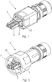
- the optical connector consists of round or rectangular housing and cable connection parts 1, 2, as they are known as standardized parts in electrical connectors.
- Fig. 3 illustrates the essential parts of the internal structure of an optical connector, which at least partially in the Fig. 1 and 2 are recognizable.
- the support part 3 Inside the housing, the support part 3 is arranged, which has two receptacles 4 for optical plug-in elements 5 and the cable strain relief element 6.
- the fibers are guided by groove-shaped recesses 8 in Jardinzugentlastungselement 6 in the receptacles 4 of the plug-in element 5 and connected there with the plug-in elements 5.
- latching elements are provided on the plug-in elements 5 and in the support part 3.
- the receptacles 4 are open laterally for laying the optical fiber.
- the plug-in elements 5 are formed in the embodiment as known LC plug contacts, so that their structure does not need to be explained in detail. It is essential that the plug-in elements by default have a locking lever 9, which must, however, remain functionless in the optical plug according to the invention. Usually, it serves to lock in the socket part (not shown in the drawing) for connecting. Due to the structural design of the optical connector, it is not possible to unlock the locking lever 9 when releasing the connection. According to the invention, therefore, a holding part 10 is provided that is adapted in its outer shape of the support member 3 and locked with this longitudinally displaceable. For locking elements 11,12 are provided on both parts.
- the groove-shaped recesses 12 in the holding part 10 allow a horizontal displacement of the holding part 10 after attachment to the support part 3 over a predetermined length. This ensures that the plug-in element-side fastening of the holding part 10 on the support part 3, the locking lever 9 pressed against the plug-in elements 5 and thus deactivated.
- the 4 to 6 show the optical connector without housing and without optical cable in the assembled state.
- the support member 3 After connection of the optical fibers, the support member 3 is fixed in the housing 1 or 2, which has either a round or an angular shape depending on the design.
Landscapes
- Physics & Mathematics (AREA)
- General Physics & Mathematics (AREA)
- Optics & Photonics (AREA)
- Mechanical Coupling Of Light Guides (AREA)
Claims (5)
- Connecteur optique comportant un boîtier (1) dans lequel sont disposés une partie de support (3) destinée à recevoir au moins un élément de connexion optique (5) et des moyens pour la fixation de câbles et de fibres et pour le soulagement de traction et qui comporte des éléments fonctionnels pour l'établissement ou l'interruption d'une liaison optique, caractérisé en ce que, pour le maintien et le positionnement latéral de l'au moins un élément de connexion (5) dans la partie de support (3), il est prévu à l'extrémité côté connecteur de la partie de support (3) une partie de retenue (10) qui est enclenchée sur la partie de support de manière à coulisser longitudinalement.
- Connecteur optique selon la revendication 1, caractérisé en ce que la forme extérieure de la partie de retenue (10) est adaptée à celle de la partie de support (3) et en ce que la partie de retenue (10) présente une forme profilée en U, dans lequel les surfaces latérales (13) de cette dernière recouvrent partiellement horizontalement et verticalement des ouvertures latérales présentes dans la partie de support (3).
- Connecteur optique selon les revendications 1 et 2, caractérisé en ce qu'un élément de soulagement de traction du câble (6) est moulé sur la partie de support, lequel élément comporte sur sa longueur des évidements (8) en forme de rainures permettant de faire passer les fibres optiques vers l'élément de connexion (5).
- Connecteur optique selon la revendication 1 et au moins l'une des revendications 2 et 3, caractérisé en ce que des éléments de guidage et d'encliquetage (11, 12) sont réalisés dans le corps de support (3) et sur la partie de retenue (10), de manière à ce que la partie de retenue (10) puisse être décalée horizontalement dans la direction de l'axe longitudinal de la partie de support (3) pour s'enclencher sur la partie de support (3).
- Connecteur optique selon la revendication 1 et au moins l'une des revendications 2 à 4, caractérisé en ce qu'au moins une protubérance est réalisée dans la partie de retenue (10), laquelle protubérance comprime des leviers d'encliquetage (9) classiques réalisés de manière élastique et présents sur des éléments de connexion optiques (5), contre l'élément de connexion (5) dans la partie de support (3).
Applications Claiming Priority (1)
| Application Number | Priority Date | Filing Date | Title |
|---|---|---|---|
| DE102006019335A DE102006019335A1 (de) | 2006-04-24 | 2006-04-24 | Optischer Stecker |
Publications (2)
| Publication Number | Publication Date |
|---|---|
| EP1860473A1 EP1860473A1 (fr) | 2007-11-28 |
| EP1860473B1 true EP1860473B1 (fr) | 2017-12-20 |
Family
ID=38477202
Family Applications (1)
| Application Number | Title | Priority Date | Filing Date |
|---|---|---|---|
| EP07008190.6A Active EP1860473B1 (fr) | 2006-04-24 | 2007-04-23 | Connecteur optique muni d'un élément de maintien verrouillable et longitudinalement déplacable dans un élément support |
Country Status (2)
| Country | Link |
|---|---|
| EP (1) | EP1860473B1 (fr) |
| DE (1) | DE102006019335A1 (fr) |
Families Citing this family (70)
| Publication number | Priority date | Publication date | Assignee | Title |
|---|---|---|---|---|
| WO2008112986A1 (fr) * | 2007-03-15 | 2008-09-18 | Senko Advanced Components, Inc. | Coffre simple pour connecteurs à fibres optiques doubles |
| DE202008005100U1 (de) * | 2008-01-21 | 2009-06-18 | Weidmüller Interface GmbH & Co. KG | Steckverbindung mit Adaptergehäusen zur Aufnahme einer Stecker- bzw. einer Buchsenanordnung |
| EP2081066B1 (fr) * | 2008-01-21 | 2019-08-14 | Weidmüller Interface GmbH & Co. KG | Connecteur à fiches doté de boîtiers d'adaptateurs destiné à la réception d'une prise ou d'un agencement de douille |
| DE102008010161B4 (de) * | 2008-02-20 | 2015-08-20 | Phoenix Contact Gmbh & Co. Kg | Steckverbinder zur Aufnahme eines Lichtwellenleiters |
| DE102008019757B4 (de) * | 2008-04-18 | 2022-08-25 | Phoenix Contact Gmbh & Co. Kg | Anschlussvorrichtung |
| US8152385B2 (en) | 2009-02-27 | 2012-04-10 | Corning Cable Systems Llc | Duplex fiber optic assemblies suitable for polarity reversal and methods therefor |
| DE102009011388B3 (de) | 2009-03-03 | 2010-08-05 | Harting Electronics Gmbh & Co. Kg | Steckverbinder für Lichtwellenleiter |
| US8408815B2 (en) | 2009-06-18 | 2013-04-02 | Senko Advanced Components, Inc. | Optical fiber connector and adapter |
| DE102010010018B4 (de) | 2010-03-03 | 2013-04-25 | HARTING Electronics GmbH | Steckverbinder für Lichtwellenleiter |
| US9188747B2 (en) | 2011-05-23 | 2015-11-17 | Senko Advanced Components, Inc. | True one piece housing fiber optic adapter |
| CN103703631B (zh) | 2011-10-05 | 2017-02-15 | 扇港元器件有限公司 | 具有远距离释放件的闩锁连接器 |
| US8974124B2 (en) | 2012-08-16 | 2015-03-10 | Senko Advanced Components, Inc. | Fiber optic connector |
| US9268103B2 (en) | 2013-05-10 | 2016-02-23 | Senko Advanced Components, Inc. | Interlockable fiber optic connector adaptors |
| US9360649B2 (en) | 2013-05-22 | 2016-06-07 | Senko Advanced Components, Inc. | Cable guide for fiber optic cables |
| US9618703B2 (en) | 2013-10-03 | 2017-04-11 | Senko Advanced Components, Inc. | Connector housing for securing an optical cable and methods of use and manufacture thereof |
| US9477049B2 (en) | 2013-12-20 | 2016-10-25 | Senko Advanced Components, Inc. | Lockable connectors and connection assemblies |
| US9535230B2 (en) | 2014-01-31 | 2017-01-03 | Senko Advanced Components, Inc. | Integrated fiber optic cable fan-out connector |
| US9297964B2 (en) | 2014-04-18 | 2016-03-29 | Senko Advanced Components, Inc. | Optical fiber connector assembly |
| US9274287B2 (en) | 2014-05-13 | 2016-03-01 | Senko Advanced Components, Inc. | Optical fiber connector and ferrule |
| US9618702B2 (en) | 2014-06-09 | 2017-04-11 | Senko Advanced Components, Inc. | Reduced-profile data transmission element connectors, adapters, and connection assemblies thereof |
| US9599778B2 (en) | 2014-10-22 | 2017-03-21 | Senko Advanced Components, Inc. | Latching connector with remote release |
| US9494745B2 (en) | 2015-01-16 | 2016-11-15 | Senko Advanced Components, Inc. | Sealable communication cable connection assemblies |
| US9658409B2 (en) | 2015-03-03 | 2017-05-23 | Senko Advanced Components, Inc. | Optical fiber connector with changeable polarity |
| US9684139B2 (en) | 2015-05-29 | 2017-06-20 | Senko Advanced Components, Inc. | Optical fiber connector with changeable gender |
| US9726830B1 (en) | 2016-06-28 | 2017-08-08 | Senko Advanced Components, Inc. | Connector and adapter system for two-fiber mechanical transfer type ferrule |
| US10228521B2 (en) | 2016-12-05 | 2019-03-12 | Senko Advanced Components, Inc. | Narrow width adapters and connectors with modular latching arm |
| US10078188B1 (en) | 2016-12-05 | 2018-09-18 | Senko Advanced Components, Inc. | Springless push/pull fiber optic connector |
| US11333836B2 (en) | 2017-01-30 | 2022-05-17 | Senko Advanced Components, Inc. | Adapter for optical connectors |
| US10185100B2 (en) | 2017-01-30 | 2019-01-22 | Senko Advanced Components, Inc | Modular connector and adapter assembly using a removable anchor device |
| US10444444B2 (en) | 2017-01-30 | 2019-10-15 | Senko Advanced Components, Inc. | Remote release tab connector assembly |
| EP3574356A4 (fr) | 2017-01-30 | 2020-08-19 | Senko Advanced Components Inc. | Connecteurs optiques à polarité réversible |
| US10416394B2 (en) | 2017-01-30 | 2019-09-17 | Senko Advanced Components, Inc. | Fiber optic receptacle with integrated device therein |
| US10725248B2 (en) | 2017-01-30 | 2020-07-28 | Senko Advanced Components, Inc. | Fiber optic receptacle with integrated device therein incorporating a behind-the-wall fiber optic receptacle |
| US9989712B1 (en) | 2017-03-20 | 2018-06-05 | Senko Advanced Components, Inc | MPO connector assembly with push-pull tab |
| US10754098B2 (en) | 2017-04-07 | 2020-08-25 | Senko Advanced Components, Inc. | Behind the wall optical connector with reduced components |
| US10209461B2 (en) | 2017-04-07 | 2019-02-19 | Senko Advanced Components | Behind the wall optical connector with reduced components |
| US10359583B2 (en) | 2017-04-07 | 2019-07-23 | Senko Advanced Components, Inc. | Behind the wall optical connector with reduced components |
| US10989884B2 (en) | 2017-04-07 | 2021-04-27 | Senko Advanced Components, Inc. | Behind the wall optical connector with reduced components |
| US10401576B2 (en) | 2017-05-10 | 2019-09-03 | Senko Advanced Components, Inc. | MPO micro-latch-lock connector |
| US10146016B1 (en) | 2017-05-10 | 2018-12-04 | Senko Advanced Components, Inc | MPO micro-latchlock connector |
| US10295759B2 (en) | 2017-05-18 | 2019-05-21 | Senko Advanced Components, Inc. | Optical connector with forward-biasing projections |
| US10359576B2 (en) | 2017-06-15 | 2019-07-23 | Senko Advanced Components, Inc. | SC low profile connector with optional boot |
| US10718911B2 (en) | 2017-08-24 | 2020-07-21 | Senko Advanced Components, Inc. | Ultra-small form factor optical connectors using a push-pull boot receptacle release |
| US10281668B2 (en) | 2017-07-14 | 2019-05-07 | Senko Advanced Components, Inc. | Ultra-small form factor optical connectors |
| US12001064B2 (en) | 2017-07-14 | 2024-06-04 | Senko Advanced Components, Inc. | Small form factor fiber optic connector with multi-purpose boot |
| US11822133B2 (en) | 2017-07-14 | 2023-11-21 | Senko Advanced Components, Inc. | Ultra-small form factor optical connector and adapter |
| US10641972B2 (en) | 2017-08-17 | 2020-05-05 | Senko Advanced Components, Inc | Anti-jam alignment sleeve holder or connector housing for a ferrule assembly |
| US10444442B2 (en) | 2017-11-03 | 2019-10-15 | Senko Advanced Components, Inc. | MPO optical fiber connector |
| US11002923B2 (en) | 2017-11-21 | 2021-05-11 | Senko Advanced Components, Inc. | Fiber optic connector with cable boot release having a two-piece clip assembly |
| US10678000B2 (en) | 2018-01-05 | 2020-06-09 | Senko Advanced Components, Inc. | Pull rod and alignment key for a fiber optic connector and adapter |
| US11112566B2 (en) | 2018-03-19 | 2021-09-07 | Senko Advanced Components, Inc. | Removal tool for removing a plural of micro optical connectors from an adapter interface |
| EP3776038B1 (fr) | 2018-03-28 | 2024-07-03 | Senko Advanced Components Inc. | Connecteur de fibre optique à petit facteur de forme avec manchon multifonctionnel |
| US11041993B2 (en) | 2018-04-19 | 2021-06-22 | Senko Advanced Components, Inc. | Fiber optic adapter with removable insert for polarity change and removal tool for the same |
| US10921528B2 (en) | 2018-06-07 | 2021-02-16 | Senko Advanced Components, Inc. | Dual spring multi-fiber optic connector |
| CN112088327A (zh) | 2018-07-15 | 2020-12-15 | 扇港元器件股份有限公司 | 超小型光学连接器和适配器 |
| US10444441B1 (en) | 2018-08-10 | 2019-10-15 | Senko Advanced Components, Inc. | Pivotable housing for a fiber optic connector |
| US11073664B2 (en) | 2018-08-13 | 2021-07-27 | Senko Advanced Components, Inc. | Cable boot assembly for releasing fiber optic connector from a receptacle |
| US10921531B2 (en) | 2018-09-12 | 2021-02-16 | Senko Advanced Components, Inc. | LC type connector with push/pull assembly for releasing connector from a receptacle using a cable boot |
| CN112955797B (zh) | 2018-09-12 | 2022-11-11 | 扇港元器件股份有限公司 | 具有用于利用缆线护套将连接器从插座释放的夹式推/拉舌片的lc型连接器 |
| US10921530B2 (en) | 2018-09-12 | 2021-02-16 | Senko Advanced Components, Inc. | LC type connector with push/pull assembly for releasing connector from a receptacle using a cable boot |
| US11806831B2 (en) | 2018-11-21 | 2023-11-07 | Senko Advanced Components, Inc. | Fixture and method for polishing fiber optic connector ferrules |
| US11175464B2 (en) | 2018-11-25 | 2021-11-16 | Senko Advanced Components, Inc. | Open ended spring body for use in an optical fiber connector |
| US11689247B2 (en) | 2019-01-16 | 2023-06-27 | Mertek Industries, Llc | Patch cord including wireless components |
| US12038613B2 (en) | 2019-03-28 | 2024-07-16 | Senko Advanced Components, Inc. | Behind-the-wall optical connector and assembly of the same |
| US11579379B2 (en) | 2019-03-28 | 2023-02-14 | Senko Advanced Components, Inc. | Fiber optic adapter assembly |
| US11340406B2 (en) | 2019-04-19 | 2022-05-24 | Senko Advanced Components, Inc. | Small form factor fiber optic connector with resilient latching mechanism for securing within a hook-less receptacle |
| CN114026480B (zh) | 2019-06-13 | 2023-05-26 | 扇港元器件有限公司 | 用于从插座端口释放光纤连接器的杆驱动闩锁臂和使用方法 |
| CN114600018B (zh) | 2019-07-23 | 2024-04-09 | 扇港元器件有限公司 | 用于接收与插芯组件相对的光纤连接器的超小型插座 |
| WO2021067241A1 (fr) | 2019-09-30 | 2021-04-08 | Mertek Industries, Llc | Système de mise en réseau traçable d'un tableau de connexions |
| CN114787677A (zh) | 2019-11-13 | 2022-07-22 | 扇港元器件有限公司 | 光纤连接器 |
Family Cites Families (4)
| Publication number | Priority date | Publication date | Assignee | Title |
|---|---|---|---|---|
| JP4081003B2 (ja) * | 2001-07-31 | 2008-04-23 | ライヒレ・ウント・デ−マサリ・アクチエンゲゼルシヤフト | 差込式コネクタのための保護装置 |
| US20030063862A1 (en) * | 2001-10-01 | 2003-04-03 | Woodhead Industries, Inc. | Holder for optical loopback assembly with release mechanism |
| US20050064752A1 (en) * | 2003-02-28 | 2005-03-24 | Alden Products Company | Ruggedized ethernet connector assembly |
| DE102004042142A1 (de) * | 2004-08-31 | 2006-03-16 | Telegärtner Gerätebau GmbH | Lichtwellenleiter-Steckverbinder |
-
2006
- 2006-04-24 DE DE102006019335A patent/DE102006019335A1/de not_active Ceased
-
2007
- 2007-04-23 EP EP07008190.6A patent/EP1860473B1/fr active Active
Non-Patent Citations (1)
| Title |
|---|
| None * |
Also Published As
| Publication number | Publication date |
|---|---|
| EP1860473A1 (fr) | 2007-11-28 |
| DE102006019335A1 (de) | 2007-10-25 |
Similar Documents
| Publication | Publication Date | Title |
|---|---|---|
| EP1860473B1 (fr) | Connecteur optique muni d'un élément de maintien verrouillable et longitudinalement déplacable dans un élément support | |
| DE102006000702B4 (de) | Anschlussvorrichtung | |
| EP2924811B1 (fr) | Connecteur à fiches électrique | |
| EP2807706B1 (fr) | Système de connexion par emboîtement pour connecteurs enfichables | |
| EP3152809B1 (fr) | Appareil électrique | |
| EP2226660B1 (fr) | Connecteur à fiche pour fibre optique | |
| EP2482109B1 (fr) | Elément de limitation de traction pour une liaison à fibre optique ainsi que cordon de brassage et système torsadé doté de cet élément de limitation de traction | |
| CH703904A2 (de) | Steckverbinder. | |
| EP3516438B1 (fr) | Connecteur et procédé de verrouillage et de déverrouillage d'un connecteur | |
| DE102016108621A1 (de) | Steckverbindergehäuse und Steckverbinder | |
| EP1467441A2 (fr) | Connecteur pour un branchement rapide à technique de pince de serrage | |
| DE102017119643A1 (de) | Komplett abgedichteter Steckverbinder mit verbesserten Haltekräften | |
| EP1777562B1 (fr) | Dispositif pour une fiche de raccordement optique | |
| DE102011052201A1 (de) | Elektrischer Steckverbinder | |
| EP1680697A1 (fr) | Connecteur optique et couplage simple et double destine a recevoir un tel connecteur | |
| DE102012217598A1 (de) | Steckverbindung und Verfahren zum Betreiben einer solchen Steckverbindung | |
| DE10323616A1 (de) | Schnellanschließbare Steckverbindung in Spannzangentechnik | |
| DE102014100063B4 (de) | Steckverbinder für Lichtwellenleiter | |
| DE102005037057B4 (de) | Optische Steckverbindung | |
| EP4622017A1 (fr) | Ensemble de terminaison d'un ensemble connecteur de câble, ensemble connecteur de câble et procédé d'assemblage d'un ensemble connecteur de câble | |
| DE20317751U1 (de) | Stecker zur Herstellung einer Lichtwellenleitersteckverbindung sowie Doppelkupplung und Receptacle zur Aufnahme eines derartigen Steckers | |
| DE10061272B4 (de) | Lichtleiter-Steckverbinder | |
| DE10253390A1 (de) | Steckverbindungsvorrichtung | |
| DE202008005462U1 (de) | Anschlussvorrichtung | |
| DE29621317U1 (de) | Fixiermittel für ein Steckverbinderteil einer elektrischen Steckverbindung |
Legal Events
| Date | Code | Title | Description |
|---|---|---|---|
| PUAI | Public reference made under article 153(3) epc to a published international application that has entered the european phase |
Free format text: ORIGINAL CODE: 0009012 |
|
| AK | Designated contracting states |
Kind code of ref document: A1 Designated state(s): AT BE BG CH CY CZ DE DK EE ES FI FR GB GR HU IE IS IT LI LT LU LV MC MT NL PL PT RO SE SI SK TR |
|
| AX | Request for extension of the european patent |
Extension state: AL BA HR MK YU |
|
| 17P | Request for examination filed |
Effective date: 20080318 |
|
| 17Q | First examination report despatched |
Effective date: 20080422 |
|
| AKX | Designation fees paid |
Designated state(s): AT BE BG CH CY CZ DE DK EE ES FI FR GB GR HU IE IS IT LI LT LU LV MC MT NL PL PT RO SE SI SK TR |
|
| GRAP | Despatch of communication of intention to grant a patent |
Free format text: ORIGINAL CODE: EPIDOSNIGR1 |
|
| INTG | Intention to grant announced |
Effective date: 20170705 |
|
| GRAS | Grant fee paid |
Free format text: ORIGINAL CODE: EPIDOSNIGR3 |
|
| GRAA | (expected) grant |
Free format text: ORIGINAL CODE: 0009210 |
|
| AK | Designated contracting states |
Kind code of ref document: B1 Designated state(s): AT BE BG CH CY CZ DE DK EE ES FI FR GB GR HU IE IS IT LI LT LU LV MC MT NL PL PT RO SE SI SK TR |
|
| REG | Reference to a national code |
Ref country code: GB Ref legal event code: FG4D Free format text: NOT ENGLISH |
|
| REG | Reference to a national code |
Ref country code: CH Ref legal event code: EP |
|
| REG | Reference to a national code |
Ref country code: IE Ref legal event code: FG4D Free format text: LANGUAGE OF EP DOCUMENT: GERMAN |
|
| REG | Reference to a national code |
Ref country code: AT Ref legal event code: REF Ref document number: 956869 Country of ref document: AT Kind code of ref document: T Effective date: 20180115 |
|
| REG | Reference to a national code |
Ref country code: DE Ref legal event code: R096 Ref document number: 502007015986 Country of ref document: DE |
|
| REG | Reference to a national code |
Ref country code: NL Ref legal event code: MP Effective date: 20171220 |
|
| PG25 | Lapsed in a contracting state [announced via postgrant information from national office to epo] |
Ref country code: FI Free format text: LAPSE BECAUSE OF FAILURE TO SUBMIT A TRANSLATION OF THE DESCRIPTION OR TO PAY THE FEE WITHIN THE PRESCRIBED TIME-LIMIT Effective date: 20171220 Ref country code: LT Free format text: LAPSE BECAUSE OF FAILURE TO SUBMIT A TRANSLATION OF THE DESCRIPTION OR TO PAY THE FEE WITHIN THE PRESCRIBED TIME-LIMIT Effective date: 20171220 Ref country code: SE Free format text: LAPSE BECAUSE OF FAILURE TO SUBMIT A TRANSLATION OF THE DESCRIPTION OR TO PAY THE FEE WITHIN THE PRESCRIBED TIME-LIMIT Effective date: 20171220 |
|
| REG | Reference to a national code |
Ref country code: LT Ref legal event code: MG4D |
|
| PG25 | Lapsed in a contracting state [announced via postgrant information from national office to epo] |
Ref country code: BG Free format text: LAPSE BECAUSE OF FAILURE TO SUBMIT A TRANSLATION OF THE DESCRIPTION OR TO PAY THE FEE WITHIN THE PRESCRIBED TIME-LIMIT Effective date: 20180320 Ref country code: LV Free format text: LAPSE BECAUSE OF FAILURE TO SUBMIT A TRANSLATION OF THE DESCRIPTION OR TO PAY THE FEE WITHIN THE PRESCRIBED TIME-LIMIT Effective date: 20171220 Ref country code: GR Free format text: LAPSE BECAUSE OF FAILURE TO SUBMIT A TRANSLATION OF THE DESCRIPTION OR TO PAY THE FEE WITHIN THE PRESCRIBED TIME-LIMIT Effective date: 20180321 |
|
| PG25 | Lapsed in a contracting state [announced via postgrant information from national office to epo] |
Ref country code: NL Free format text: LAPSE BECAUSE OF FAILURE TO SUBMIT A TRANSLATION OF THE DESCRIPTION OR TO PAY THE FEE WITHIN THE PRESCRIBED TIME-LIMIT Effective date: 20171220 |
|
| PG25 | Lapsed in a contracting state [announced via postgrant information from national office to epo] |
Ref country code: EE Free format text: LAPSE BECAUSE OF FAILURE TO SUBMIT A TRANSLATION OF THE DESCRIPTION OR TO PAY THE FEE WITHIN THE PRESCRIBED TIME-LIMIT Effective date: 20171220 Ref country code: CY Free format text: LAPSE BECAUSE OF FAILURE TO SUBMIT A TRANSLATION OF THE DESCRIPTION OR TO PAY THE FEE WITHIN THE PRESCRIBED TIME-LIMIT Effective date: 20171220 Ref country code: CZ Free format text: LAPSE BECAUSE OF FAILURE TO SUBMIT A TRANSLATION OF THE DESCRIPTION OR TO PAY THE FEE WITHIN THE PRESCRIBED TIME-LIMIT Effective date: 20171220 Ref country code: SK Free format text: LAPSE BECAUSE OF FAILURE TO SUBMIT A TRANSLATION OF THE DESCRIPTION OR TO PAY THE FEE WITHIN THE PRESCRIBED TIME-LIMIT Effective date: 20171220 Ref country code: ES Free format text: LAPSE BECAUSE OF FAILURE TO SUBMIT A TRANSLATION OF THE DESCRIPTION OR TO PAY THE FEE WITHIN THE PRESCRIBED TIME-LIMIT Effective date: 20171220 |
|
| PG25 | Lapsed in a contracting state [announced via postgrant information from national office to epo] |
Ref country code: IT Free format text: LAPSE BECAUSE OF FAILURE TO SUBMIT A TRANSLATION OF THE DESCRIPTION OR TO PAY THE FEE WITHIN THE PRESCRIBED TIME-LIMIT Effective date: 20171220 Ref country code: RO Free format text: LAPSE BECAUSE OF FAILURE TO SUBMIT A TRANSLATION OF THE DESCRIPTION OR TO PAY THE FEE WITHIN THE PRESCRIBED TIME-LIMIT Effective date: 20171220 Ref country code: IS Free format text: LAPSE BECAUSE OF FAILURE TO SUBMIT A TRANSLATION OF THE DESCRIPTION OR TO PAY THE FEE WITHIN THE PRESCRIBED TIME-LIMIT Effective date: 20180420 Ref country code: PL Free format text: LAPSE BECAUSE OF FAILURE TO SUBMIT A TRANSLATION OF THE DESCRIPTION OR TO PAY THE FEE WITHIN THE PRESCRIBED TIME-LIMIT Effective date: 20171220 |
|
| REG | Reference to a national code |
Ref country code: DE Ref legal event code: R097 Ref document number: 502007015986 Country of ref document: DE |
|
| PG25 | Lapsed in a contracting state [announced via postgrant information from national office to epo] |
Ref country code: MT Free format text: LAPSE BECAUSE OF FAILURE TO SUBMIT A TRANSLATION OF THE DESCRIPTION OR TO PAY THE FEE WITHIN THE PRESCRIBED TIME-LIMIT Effective date: 20171220 |
|
| PLBE | No opposition filed within time limit |
Free format text: ORIGINAL CODE: 0009261 |
|
| STAA | Information on the status of an ep patent application or granted ep patent |
Free format text: STATUS: NO OPPOSITION FILED WITHIN TIME LIMIT |
|
| 26N | No opposition filed |
Effective date: 20180921 |
|
| PG25 | Lapsed in a contracting state [announced via postgrant information from national office to epo] |
Ref country code: DK Free format text: LAPSE BECAUSE OF FAILURE TO SUBMIT A TRANSLATION OF THE DESCRIPTION OR TO PAY THE FEE WITHIN THE PRESCRIBED TIME-LIMIT Effective date: 20171220 Ref country code: MC Free format text: LAPSE BECAUSE OF FAILURE TO SUBMIT A TRANSLATION OF THE DESCRIPTION OR TO PAY THE FEE WITHIN THE PRESCRIBED TIME-LIMIT Effective date: 20171220 |
|
| REG | Reference to a national code |
Ref country code: BE Ref legal event code: MM Effective date: 20180430 |
|
| GBPC | Gb: european patent ceased through non-payment of renewal fee |
Effective date: 20180423 |
|
| REG | Reference to a national code |
Ref country code: IE Ref legal event code: MM4A |
|
| PG25 | Lapsed in a contracting state [announced via postgrant information from national office to epo] |
Ref country code: LU Free format text: LAPSE BECAUSE OF NON-PAYMENT OF DUE FEES Effective date: 20180423 |
|
| PG25 | Lapsed in a contracting state [announced via postgrant information from national office to epo] |
Ref country code: SI Free format text: LAPSE BECAUSE OF FAILURE TO SUBMIT A TRANSLATION OF THE DESCRIPTION OR TO PAY THE FEE WITHIN THE PRESCRIBED TIME-LIMIT Effective date: 20171220 Ref country code: GB Free format text: LAPSE BECAUSE OF NON-PAYMENT OF DUE FEES Effective date: 20180423 Ref country code: BE Free format text: LAPSE BECAUSE OF NON-PAYMENT OF DUE FEES Effective date: 20180430 |
|
| PG25 | Lapsed in a contracting state [announced via postgrant information from national office to epo] |
Ref country code: IE Free format text: LAPSE BECAUSE OF NON-PAYMENT OF DUE FEES Effective date: 20180423 Ref country code: FR Free format text: LAPSE BECAUSE OF NON-PAYMENT OF DUE FEES Effective date: 20180430 |
|
| REG | Reference to a national code |
Ref country code: AT Ref legal event code: MM01 Ref document number: 956869 Country of ref document: AT Kind code of ref document: T Effective date: 20180423 |
|
| PG25 | Lapsed in a contracting state [announced via postgrant information from national office to epo] |
Ref country code: AT Free format text: LAPSE BECAUSE OF NON-PAYMENT OF DUE FEES Effective date: 20180423 |
|
| PG25 | Lapsed in a contracting state [announced via postgrant information from national office to epo] |
Ref country code: TR Free format text: LAPSE BECAUSE OF FAILURE TO SUBMIT A TRANSLATION OF THE DESCRIPTION OR TO PAY THE FEE WITHIN THE PRESCRIBED TIME-LIMIT Effective date: 20171220 |
|
| PG25 | Lapsed in a contracting state [announced via postgrant information from national office to epo] |
Ref country code: HU Free format text: LAPSE BECAUSE OF FAILURE TO SUBMIT A TRANSLATION OF THE DESCRIPTION OR TO PAY THE FEE WITHIN THE PRESCRIBED TIME-LIMIT; INVALID AB INITIO Effective date: 20070423 Ref country code: PT Free format text: LAPSE BECAUSE OF FAILURE TO SUBMIT A TRANSLATION OF THE DESCRIPTION OR TO PAY THE FEE WITHIN THE PRESCRIBED TIME-LIMIT Effective date: 20171220 |
|
| PGFP | Annual fee paid to national office [announced via postgrant information from national office to epo] |
Ref country code: DE Payment date: 20250417 Year of fee payment: 19 |
|
| PGFP | Annual fee paid to national office [announced via postgrant information from national office to epo] |
Ref country code: CH Payment date: 20250501 Year of fee payment: 19 |