EP1860582A1 - Vorrichtung, verfahren und programm zur simulation und computerlesbares aufzeichnungsmedium, in dem dieses programm aufgezeichnet wurde - Google Patents
Vorrichtung, verfahren und programm zur simulation und computerlesbares aufzeichnungsmedium, in dem dieses programm aufgezeichnet wurde Download PDFInfo
- Publication number
- EP1860582A1 EP1860582A1 EP05720996A EP05720996A EP1860582A1 EP 1860582 A1 EP1860582 A1 EP 1860582A1 EP 05720996 A EP05720996 A EP 05720996A EP 05720996 A EP05720996 A EP 05720996A EP 1860582 A1 EP1860582 A1 EP 1860582A1
- Authority
- EP
- European Patent Office
- Prior art keywords
- boundary surface
- nodes
- level value
- section
- simulating
- Prior art date
- Legal status (The legal status is an assumption and is not a legal conclusion. Google has not performed a legal analysis and makes no representation as to the accuracy of the status listed.)
- Granted
Links
Images


Classifications
-
- G—PHYSICS
- G11—INFORMATION STORAGE
- G11B—INFORMATION STORAGE BASED ON RELATIVE MOVEMENT BETWEEN RECORD CARRIER AND TRANSDUCER
- G11B5/00—Recording by magnetisation or demagnetisation of a record carrier; Reproducing by magnetic means; Record carriers therefor
- G11B5/127—Structure or manufacture of heads, e.g. inductive
- G11B5/33—Structure or manufacture of flux-sensitive heads, i.e. for reproduction only; Combination of such heads with means for recording or erasing only
- G11B5/39—Structure or manufacture of flux-sensitive heads, i.e. for reproduction only; Combination of such heads with means for recording or erasing only using magneto-resistive devices or effects
-
- G—PHYSICS
- G06—COMPUTING OR CALCULATING; COUNTING
- G06F—ELECTRIC DIGITAL DATA PROCESSING
- G06F30/00—Computer-aided design [CAD]
- G06F30/20—Design optimisation, verification or simulation
- G06F30/23—Design optimisation, verification or simulation using finite element methods [FEM] or finite difference methods [FDM]
Definitions
- the present invention relates to a technique of simulation on the shape formed by processes for a multilayer film exemplified by a semiconductor and a MR (Magneto-Resistive) head.
- Patent reference 1 discloses a shape simulation, method in which an analysis region is divided into cells (perpendicular grids), a volume ratio is defined for each cell so that the shapes of a number of materials are expressed.
- a cell size however needs to be set as small as the film thickness in order to express the formation of a multilayer film structure, e.g., a MR (Magneto-Resistive) head used for a hard disk drive, formed by depositing films having the thickness of several angstroms whereby a large volume of the memory region is occupied and calculation cannot be avoided taking a long time.
- MR Magnetic-Resistive
- the object of the present invention is improvement in memory consumption amount and calculation speed by expressing the shape formed by a number of materials smaller in size than the mesh element size, thereby making the mesh element size larger.
- a simulation apparatus for simulating the conformation of a structure, comprising: a mesh dividing section for dividing an analysis object region including the structure into a plurality of mesh elements, each of which formed by a number of nodes and a number of grid lines that connects the nodes; a process condition setting section for setting a calculation condition for a process to be performed on the structure; a boundary surface simulating section for simulating a change in a shape of a boundary surface of the structure which change is caused from the process using the calculation condition set by the process condition setting section; a level value determining section for determining level values each of which concerns a distance between one of the nodes and the boundary surface on the basis of the shape of the boundary surface whose change has been simulated by the boundary surface simulating section; and a level value data retaining section for retaining, for each of the nodes, the level values, serving as level value data, determined by the level value determining section in association with the boundary surface.
- the simulation apparatus may further comprise: a process data retaining section for retaining process data which associates the boundary surface with data concerning the process to form the boundary surface; a position determining section for determining a verification position that is to be used for verifying the conformation of the structure; an interpolation calculating section for performing an interpolation calculation on the level values on the basis of the verification position determined by the position determining section; a boundary surface specifying section for specifying one boundary surface from at least two of the boundary surfaces, the one boundary surface being in association with the level values satisfying a boundary surface selecting condition predetermined with reference to the level value data on the basis of the level values on which the interpolation has been performed by the interpolation calculating section; an information obtaining section for obtaining, on the basis of the one boundary surface specified by the boundary surface specifying section, the data concerning the process associated with the one boundary surface with reference to the process data; and an outputting section for outputting the data concerning the process obtained by the information obtaining section as data concerning the process to be performed on the verification position.
- the simulation apparatus may further comprise a maximum level value retaining section for retaining one of the maximum level values which is associated with the maximum distance among the distances between the nodes and the boundary surface as a maximum level value, and/or a minimum level value retaining section for retaining one of the minimum level values which is associated with the minimum distance among the distances between the nodes and the boundary surface as a minimum level value.
- the level value data retaining section may retain the level values such that each of the nodes is associated with the level values concerning two or more of the processes.
- a simulation method for simulating the conformation of a structure comprising the steps of: dividing an analysis object region including the structure into a plurality of mesh elements, each of which is formed by a number of nodes and a number of grid lines that connect the nodes; setting a calculation condition for a process to be performed on the structure; simulating a change in a shape of a boundary surface of the structure which change is caused from the process using the calculation condition set in the step of setting; determining level values each of which concerns a distance between one of the nodes and the boundary surface on the basis of the shape of the boundary surface whose change has been calculated in the step of simulating; and retaining, for each of the nodes, the level values, serving as level value data , determined in the step of determining in association with the boundary surface.
- the simulation method further comprise the step of retaining process data which associates the boundary surface with data concerning the process to form the boundary surface; determining a verification position that is to be used for verifying the conformation of the structure; performing an interpolation calculation on the level values on the basis of the verification position determined in the step of determining; specifying one boundary surface from at least two of the boundary surfaces, the one boundary surface being in association with the level values satisfying a boundary surface selecting condition predetermined with reference to the level value data retained in the step of retaining the level values as the level value data on the basis of the level values on which the interpolation has been performed in the step of performing the interpolation; obtaining, on the basis of the one boundary surface specified in the step of specifying, the data concerning the process associated with the one boundary surface specified in the step of specifying with reference to the process data retained in the step of retaining process data; and outputting the data concerning the process obtained in the step of obtaining the data as data concerning the process to be performed on the verification position.
- the simulation method may further comprise the steps of retaining one of the level maximum values which is associated with the maximum distance among the distances between the nodes and the boundary surface as a maximum level value, and/or retaining one of the minimum level values, which is associated with the minimum distance among the distances between the nodes and the boundary surface as a minimum level value.
- the simulation method may carry out the step of retaining the level values as the level value data such that each of the nodes is associated with the level values concerning two or more of the processes.
- a simulation program for simulating the conformation of a structure instructing a computer to execute the steps of: dividing an analysis object region including the structure into a plurality of mesh elements, each of which is formed by a number of nodes and a number of grid lines that connect the nodes; setting a calculation condition for a process to be performed on the structure; simulating a change in a shape of a boundary surface of the structure which change is caused from the process using the calculation condition set in the step of setting; determining level values each of which concerns a distance between one of the nodes and the boundary surface on the basis of the shape of the boundary surface whose change has been simulated in the step of calculating simulating; and retaining, for each of the nodes, the level values, serving is level value data, determined in the step of determining in association with the boundary surface.
- the simulation program may instruct the computer to further execute the steps of: retaining process data which associates the boundary surface with data concerning the process to form the boundary surface; determining a verification position that is to be used for verifying the conformation of the structure; performing an interpolation calculation on the level values on the basis of the verification position determined in the step of obtaining; specifying one boundary surface from at least two of the boundary surfaces, one boundary surface being in association with the level values satisfying a boundary surface selecting condition predetermined with reference to the level value data retained in the step of retaining the level values as the level value data on the basis of the level values on which the interpolation has been performed in the step of performing the interpolation; obtaining, on the basis of the one boundary surface specified in the step of specifying, the data concerning the process associated with the one boundary surface specified in the step of specifying with reference to the process data retained in the step of retaining process data; and outputting the data concerning the process obtained in the step of obtaining the data as data concerning the process to be performed on the verification position.
- the simulation program may instruct the computer to further execute the steps of retaining one of the maximum level values, which is associated with the maximum distance among the distances between the nodes and the boundary surface as a maximum level value and/or retaining one of the minimum level values which is associated with the minimum distance among the distances between the nodes and the boundary surface as a minimum level value.
- the simulation program may instruct the computer to carry out the step of retaining the level values as the level value data such that each of the nodes is associated with the level values concerning two or more of the processes.
- the computer-readable recording medium of the present invention retains the above simulation program.
- the present invention makes it possible to express a number of materials being smaller in size than the mesh element. Consequently, the mesh element size can be set larger to improve the memory consumption amount and the calculation speed.
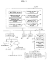
- Fig. 1 schematically shows the configuration of the simulation apparatus according to the first embodiment of the present invention.
- Fig. 2 schematically shews a fragmentary section of a multilayer film the conformation of which is to be simulated by the simulation apparatus.
- Fig. 2 shows the side section of multilayer film 3 by partially cutting.
- Simulation apparatus 1 simulates the conformation of a structure, e.g., a multilayer film such as a semiconductor or a MR (Magneto-Resistive) head, produced by forming (depositing) layers made from a number or materials and performing processes such as etching or cutting on the surface thereof.
- Simulation apparatus 1 is served by a personal computer capable of realizing various functions by executing an OS (Operating System) and applications in CPU 10, and takes the form of a computer system equipped with CPU 10, HDD 20, I/O interface 21, ROM 22, RAM 23, monitor 26, keyboard 24, mouse 25, and bus 27, as shown in Fig. 1.
- OS Operating System
- Multilayer film 3 has a layered conformation formed by successively depositing four materials-material a, material b, material c and material d.
- the first embodiment assumes that material a, material b, material c, and material d that form multilayer film 3 are different.
- FIG. 2 illustrates a process in which material d is being deposited after depositing of material a, material b and material c, and represents material d with the dotted line.
- the simulation apparatus 1 performs simulation on the conformation of multilayer film 3 so that a material (data concerning a process) at an arbitrary position of the multilayer film 3 can be grasped (material judgment can be realized).
- Monitor (outputting section) 26 displays various data and, for example, takes the form of a CRT (Cathode Ray Tube) display or a LCD (Liquid Crystal Display) display. Monitor 26 displays data (to be described below) concerning a process which data is obtained by a data obtaining section that is to be described below and thereby functions as an outputting section for outputting the data concerning a process.
- CTR Cathode Ray Tube
- LCD Liquid Crystal Display
- Monitor 26 is controlled by I/O interface 21 that is to be described below.
- Keyboard 24 allows an operator to key-input various data pieces
- mouse 25 allows the operator to select and input various information pieces by moving and clicking pointer (not shown) displayed on monitor 26.
- I/O interface 21 controls input via inputting device such as keyboard 24 and mouse 25, and controls output to outputting device of monitor 26.
- simulation apparatus 1 includes, as inputting devices, keyboard 24 and mouse 25, to which the inputting device should by no means be limited.
- the inputting means may be a device (e.g., a flexible disk drive, a CD-ROM drive, or a DVD drive) that is able to read data from various media such as a flexible disk, a CD (e.g., CD-ROM, CD-R, or CD-RW), a DVD (e.g., DVD-ROM, DVD-RAM, DVD-R, DVD+R, DVD-RW, DVD+RW), a LAN (Local Area Network) and others.
- the I/O interface 21 may control such inputting means.
- simulation apparatus 1 of the first embodiment includes monitor 26 serving as an outputting section, but should by no means be limited to the monitor.
- the outputting section may be exemplified by a device (e.g., a flexible disk drive, a CD-ROM drive, or a DVD drive) able to output data to various media such as a flexible disk, a CD, a DVD and paper, a LAN, a printer unit and others.
- I/O interface 21 may control such outputting means, and the outputting means may output (file output) data in the form of a data file usable by another application and another information processor.
- ROM (Read Only Memory) 22 retains various data and applications, and CPU 10 to be described below carries out various arithmetic operations using data retained in the ROM 22 and the like.
- RAM (Random Access Memory) 23 temporarily retains various data and applications, and used for temporarily retaining and expending data when CPU 10 to be described below is to perform arithmetic operations.
- HDD 20 is a storage unit able to retain an OS, various data and application ready to be written and read. As described below, HDD 20 functions as a level value data retaining section which retains level value data 28 in which a level value determined by level value determining section 14 is associated with a boundary surface. In addition, HDD 20 also function as a process data retaining section which retains process data 29 in which a boundary surface is associated with a process that forms the boundary surface, as detailed below.
- HDD 20 also functions as a maximum level value retaining section which retains a level value (the maximum level value ⁇ max) which represents the level value when a distance between a node and a boundary surface is maximum, and a minimum level value retaining section which retains a level value the minimum level value ⁇ min) which represents the level value when a distance between a node and a boundary surface is minimum.
- Bus 27 communicably interconnects CPU 10, I/O interface 21, ROM 22, RAM 23, and HDD 20.
- CPU 10 realizes various functions by executing an OS and applications stored in HDD 20, ROM 22, and RAM 23.
- CPU 10 executing a simulation program functions as mesh dividing section 11, process condition setting section 12, boundary surface simulating section 13, level value determining section 14, position obtaining section 15, interpolation calculating section 16, boundary surface specifying section 17, and data obtaining section 18.
- a program (simulation program) to realize the functions for mesh dividing section 11, process condition setting section 12, boundary surface simulating section 13, level value determining section 14, position obtaining section 15, interpolation calculating section 16, boundary surface specifying section 17, and data obtaining section 18 is provided in the form of being recorded in a computer-readable recording medium exemplified by a flexible disk, a CD, a DVD, a magnetic disk, an optical disk, or magneto-optical disk.
- the computer reads the program from the receding medium and sends the read program to store into an internal or external memory for future use.
- the program may be previously recorded in a storage unit (a recording medium) exemplified by a magnetic disk, an optical disk or a magnet-optical disk, and provided to a computer from the storage unit through communication path.
- a microprocessor executes the simulation program stored in an internal storage unit (in the illustrated example, ROM 22 or RAM 23).
- the computer may read a simulation program from a recording medium and executes the read program.
- the concept of a computer in this embodiment includes hardware and an OS (Operating System) and means hardware that operates under control of the OS. If an application program independently operates hardware, requiring no OS, the hardware itself corresponds to a computer.
- Hardware includes at least a microprocessor such as a CPU and means for reading a computer program recorded in a recording medium.
- simulation apparatus 1 has a function as such a computer.
- the recording medium used in this embodiment may be one from various computer-readable recording medium incorporates in the form of an IC card, a ROM cartridge, a magnetic tape, a punch card, an internal memory (such as a RAM or a ROM) in a computer, an external memory, or a printed matter on which codes such as bar codes are printed, other than the above examples of a flexible disk, a CD, a DVD, a magnetic disk, an optical disk and a magneto-optical disk.
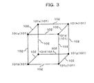
- Fig. 3 is a diagram illustrating an example of a cell (a mesh element) 100 formed by mesh dividing section 11 of the simulation apparatus 10 according to the first embodiment.
- Cell 100 is, as shown in Fig. 3, an element of a hexahedron formed by a number of nodes 101 (101a, 101b, 101c, 101d, 101e, 101f, 101g, 101h) and grid lines connecting these nodes 101.
- Mesh dividing section 11 divides an analysis object region including multilayer film 3 into two or more cells 100.
- mesh dividing section 11 mesh-divides an analysis object region into cells 100 in the form of hexahedron elements whereby an arbitrary point of an analysis object region is included in one of a number of cells 100 which are created by mesh division and which are successively arranged in the vertical and horizontal directions.
- nodes that form cell 100 are represented by reference numbers 101a, 101b, 101c, 101d, 101e, 101f, 101g, and 101h.
- reference numbers 102a, 101b, 101c, 101d, 101e, 101f, 101g, and 101h are used if one particular nodes need to be discriminated from the others, but an arbitrary node is represented by reference number 101.
- Process condition setting section 12 sets a simulation calculation condition (a calculation condition) for a process to be performed on multilayer film 3, and, for example, sets a simulation calculation condition for a process such as depositing (film depositing), etching and cutting that is to be performed on the surface of multilayer film 3 being fabricated.
- process condition setting section 12 sets, as calculation conditions, parameters for calculation accuracy such as the number of time steps and the number of meshes besides amounts of cutting, layer formation, and depositing and substance constant.
- Boundary surface simulating section 13 simulates a change in the shape of a boundary surface subjected to a process using a calculation condition set by process condition setting section 12 to obtain the shape of the surface (the boundary surface) after being subjected to a process on the basis of a calculation condition set by process condition setting section 12.
- a boundary surface represents each individual surface of materials a, b, c, and d, which form multilayer film 3, as shown in Fig. 2, and includes faces shaped by a process, such as etching or cutting, performed on the materials a, b, c, and d besides faces formed by depositing materials a, b, c, and d.
- Level value determining section 14 determines, on the basis of the face shape calculated by boundary surface simulating section 13, a level value ⁇ for each node 101 which value concerns a distance between the node and a boundary surface.
- a level value ⁇ represents a distance between node 101 and the boundary surface of each of materials a, b, c, and d which form multilayer film 3, and the absolute value of the level value ⁇ is a distance from the boundary surface.
- Level values ⁇ represent shapes of a number of materials and a level value ⁇ is created for a calculation concerning each process or each material.
- one or more level values ⁇ are added accordingly to a boundary surface that has been subjected to a process each time a process has been completed.
- a level value ⁇ for node 101 e.g., nodes 101b and 101c in Fig. 2) inside the structure (multilayer film 3) is marked with a - (read as minus) sign; and a level value for node 101 (e.g., nodes 101a and 101d in Fig. 2) outside the structure (multilayer film 3) is marked with a + (read as plus) sign.
- a level value ⁇ [n] represents a level value wi th respect to a boundary surface of a material forming n-th layer (where, n is a natural number) of multilayer film 3.
- the example shown in Fig. 2 is in the process of forming material d as described above, and therefore illustrates a state in which the surface (a portion the shape of which is changing) is focused.
- the level values ⁇ with respect to the boundary surfaces of materials a, b, c, and d are stored, for each node, in HDD 20 as level value data 28 in which the level values are associated with the boundary surfaces.
- a level value ⁇ is stored as level value data 28 in HDD 20, being associated with the number NL (NL is a natural number) for specifying a layer (material) whose surface is serving as a boundary surface and with a code or the like for specifying a node 101.
- process data 29 in which information of a boundary surface is associated with information of a process performed to form the boundary surface is stored.
- process data 23 of the present embodiment associates the number NL to specify a boundary surface with information (material information, data concerning a process) concerning a material which is specified by the number NL.
- Position obtaining section 15 obtains a verification position used to verify the conformation of multilayer film 3 by receiving an input from an operator via keyboard 24 or 25, or by obtaining a coordinate (a verification position) of a material judgment position notified from another application via I/O interface 21.
- position obtaining section 15 specifies, on the basis of the obtained coordinate of a material judgment position, cell 100 including the coordinate of the material judgment position from a number of cells 100 vertically and horizontally succeeded over an analysis object region.
- Interpolation calculating section 16 carries out an interpolation calculation using interpolation formula (1) shown below for a level value using the verification position coordinate (SX, SY, SZ) obtained by position obtaining section 15.
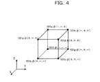
- Fig. 4 explains interpolation formula (1) used by interpolation calculating section 16 cf the simulation apparatus 10 according to the first embodiment.
- level values set for nodes 101a, 101b, 101c, 101d, 101e, 101f, 101g, and 101h that form cell 100 shown in Fig. 3 is represented by ⁇ (+,-,+), ⁇ (+,-,-), ⁇ (-,+,-), ⁇ (+,+,+), ⁇ (-,-,+), ⁇ (-,-,-), ⁇ (-,+,-), and ⁇ (-,+,+), respectively.
- ⁇ (+,+,+) represents level values ⁇ [1] ⁇ [2], ⁇ [3], ⁇ now set for node 101d in Fig. 2.
- the length (the cell size) of each side of cell 100 shown in Fig. 4 assumes to be 1.
- Interpolation calculating section 16 obtains level values ⁇ set for each node 101 that forms cell 100 specified by the position obtaining section 15 and performs an arithmetic operation of the above-described interpolation formula using the level values whereby the interpolation calculation for each level value is carried out.
- Boundary surface specifying section 17 specifies, with reference to the level value data 28 stored in HDD 20 on the basis of a level value ⁇ calculated by interpolation calculating section 16, a material corresponding to a level value that satisfies a material selecting condition previously determined.
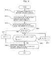
- a flow chart to judge satisfaction of a material selecting condition is shown in Fig. 6.
- the material selecting conditions are: (1) level value ⁇ [NL] being smaller than 0 (zero) and the level value ⁇ [NL-1] being equal to or larger than 0 and (2) NL being 0. NL being -1 represents the absence of a material on the position in question.
- Data obtaining section 18 obtains, with reference to process data 29 stored in HDD 20 on the basis of a boundary surface specified by boundary surface specifying section 17, data (in the illustrated example, material data) concerning the process corresponding to the specified boundary surface.
- the material data obtained by data obtaining section 18 is output to monitor 26 to be the material data for a material judgment position and is consequently notified to an operator.
- mesh dividing section 11 first of all divides an analysis object region including multilayer film 3 into a number of cells 100 (the mesh dividing step), so that simulation for the fabrication of multilayer film 3 is to be performed on the analysis object region which has been divided into the meshes.
- level values are determined for each node 101 in cell 100 in the analysis object region with respect to all the boundary surfaces of the layers that form multilayer film 3.
- a selection is made for a process that is to be carried cut as the first step performed on the surface in the fabrication of multilayer film 3.
- process condition setting section 12 sets a calculation condition for the process that is to be performed on the surface in the production of multilayer film 3 (step A20, the process condition setting step).
- Boundary surface simulating section 13 calculates the level values ⁇ now, ⁇ max and ⁇ min corresponding to the surface shape (the boundary surface shape) being subjected to each process on the basis of the calculation condition set by process condition setting section 12 (step A30, the boundary surface calculation step, the level value determining step, the minimum level value determining step).
- level value determining section 14 judges whether the process is corresponding to "A: a process moving the boundary surface only inward (e.g., etching or development) ", "B: a process moving the boundary surface only outward (e.g., film formation)", or "C: a process having a possibility of moving face inward and outward” (step A40).
- the process corresponds to "A: a process moving the boundary surface only inward” or “B: a process moving the boundary surface only outward (e.g., film formation) " (routes A and B of step A40)
- Level value determining section 14 judges whether or not the procedure has been carried out on all the processes that are to be executed in the fabrication of multilayer film 3 (step A70), and if the procedure has not been performed on all the processes (NO route of step A70), the procedure move to concern the next process (step A80) to perform step A20.
- position obtaining section 15 Upon operator's input of a material judgment position via keyboard 24 or mouse 25, for example, position obtaining section 15 obtains the coordinate of the material judgment position (step B10, the position obtaining step) to specify cell 100 which includes the coordinate of the material judgment position. If another program such as a drawing program displays the shape, the program designates the material judgment position.
- interpolation calculating section 16 calculates, on the basis of the coordinate SX, SY, SZ) of the material judgment position obtained by position obtaining section 15 and the level value ⁇ set for each node 101 of the cell 100 selected in step B10, a level value ⁇ of the material judgment position (by the interpolation calculation) using the interpolation formula (1) described above (step B20, the interpolation calculating step).
- interpolation calculating section 16 obtains, with reference to level value data 28 stored in HDD 20, the total number NLMax of level values stored and sets the number NLMax into the variable NL to initialize the variable NL (step B30).
- step B30 since verification is conducted on layers sequentially from outer surfaces (i.e. in order of later formation), there is no problem in verification even if a layer that has once formed is cut (deleted) in the fabrication process.
- the variable NL is obtained (output) and data obtaining section 18 obtains, with reference to level value data 28 stored in HDD 20, a material used in the NL-th step in the fabrication of multilayer film 3 to be a material present at the material judgment position (the information obtaining step) to complete the procedure (step B80). Then the obtained material information is output to and displayed on monitor 26 for notification to the operator (the outputting step).
- the simulation apparatus 10 determines level values ⁇ for each node 101 which values concern the distances between the node and boundary surfaces of multilayer film 3, the conformation of multilayer film 3 can be expressed by these level values ⁇ , with which the conformation of multilayer film 3 can be expressed irrespective of the cell size. That makes it possible to express the shapes of number of materials that are smaller in size than the cell size and additionally to allow the cell size to be large, resulting in improvement of memory consumption amount and calculation speed.
- mesh dividing section 11 mesh-divides an analysis object region into cubic cells 100, but the shape of cell 100 should by no means be limited to a cube.
- cell 100 created by mesh-division may take any shape exemplified by a tetrahedron element, orthogonal grid, or an octree mesh.
- interpolation calculating section 16 uses another interpolation formula suitable for the shape of a cell, as a substitute for interpolation formula (1), in order to carry cut an interpolation calculation for a level value of a verification position.
- a substitute interpolation formula can be obtained with reference-to fundamental of finite element method in fluids (written by Takehisa Hara, published by Shokodo Co., Ltd.) and others.
- the above first embodiment simulate the shape of multilayer film 3, to which should by no means be limited.
- the simulation may be performed on a shape of a semiconductor part such as an LSI.
- the present invention can be applied to simulation on a structure formed by depositing a number of materials and on a structure formed by a number of processes subsequently performed on the surface thereof.
- the above first embodiment simulates on the shape of a structure formed by sequentially depositing materials a, b, c and d dimensions of which do not reduce during the fabrication.
- the structure should by no means be limited to such a structure.
- the structure may be fabricated by a process, such as etching or cutting, which reduces the dimension of a material.
- level value data 28 and process data 29 are separately prepared, but the preparation should by no means be limited to this.
- level value data 28 and process data 29 may be provided in the form of a single common database.
- the present invention can be applied to simulation on a structure formed by depositing a number of materials and a structure formed by sequentially performing a number of processes on the surface thereof.
Landscapes
- Engineering & Computer Science (AREA)
- Physics & Mathematics (AREA)
- Theoretical Computer Science (AREA)
- Computer Hardware Design (AREA)
- Evolutionary Computation (AREA)
- Geometry (AREA)
- General Engineering & Computer Science (AREA)
- General Physics & Mathematics (AREA)
- Manufacturing & Machinery (AREA)
- Management, Administration, Business Operations System, And Electronic Commerce (AREA)
Applications Claiming Priority (1)
| Application Number | Priority Date | Filing Date | Title |
|---|---|---|---|
| PCT/JP2005/004809 WO2006098034A1 (ja) | 2005-03-17 | 2005-03-17 | シミュレーション装置,シミュレーション方法,シミュレーション用プログラムおよび同プログラムを記録したコンピュータ読取可能な記録媒体 |
Publications (3)
| Publication Number | Publication Date |
|---|---|
| EP1860582A1 true EP1860582A1 (de) | 2007-11-28 |
| EP1860582A4 EP1860582A4 (de) | 2010-03-31 |
| EP1860582B1 EP1860582B1 (de) | 2011-09-14 |
Family
ID=36991394
Family Applications (1)
| Application Number | Title | Priority Date | Filing Date |
|---|---|---|---|
| EP05720996A Expired - Lifetime EP1860582B1 (de) | 2005-03-17 | 2005-03-17 | Vorrichtung, verfahren und programm zur simulation und computerlesbares aufzeichnungsmedium, in dem dieses programm aufgezeichnet wurde |
Country Status (5)
| Country | Link |
|---|---|
| US (1) | US7813905B2 (de) |
| EP (1) | EP1860582B1 (de) |
| JP (1) | JP4792460B2 (de) |
| KR (1) | KR100944697B1 (de) |
| WO (1) | WO2006098034A1 (de) |
Cited By (1)
| Publication number | Priority date | Publication date | Assignee | Title |
|---|---|---|---|---|
| CN107515922A (zh) * | 2017-08-23 | 2017-12-26 | 北京汽车研究总院有限公司 | 一种数据管理方法及系统 |
Families Citing this family (3)
| Publication number | Priority date | Publication date | Assignee | Title |
|---|---|---|---|---|
| US8274512B2 (en) * | 2008-06-04 | 2012-09-25 | Sandia Corporation | System and method for polytopic mesh refinement |
| US20140365940A1 (en) * | 2013-06-07 | 2014-12-11 | Solar Turbines Incorporated | Systems and methods for manipulating boundary conditions |
| CN111984916B (zh) * | 2020-10-09 | 2021-01-12 | 北京应用物理与计算数学研究所 | 一种数理方程解算构件及并行软件研发方法与系统 |
Family Cites Families (12)
| Publication number | Priority date | Publication date | Assignee | Title |
|---|---|---|---|---|
| JP2507696B2 (ja) | 1990-09-26 | 1996-06-12 | 三菱電機株式会社 | 形状シミュレ―ション方法 |
| JPH08292938A (ja) * | 1995-02-24 | 1996-11-05 | Fujitsu Ltd | 有限要素メッシュ発生方法及び装置、並びに解析方法及び装置 |
| US6556702B1 (en) * | 1999-01-06 | 2003-04-29 | Applied Materials, Inc. | Method and apparatus that determines charged particle beam shape codes |
| JP3388203B2 (ja) * | 1999-05-28 | 2003-03-17 | 株式会社半導体先端テクノロジーズ | 形状シミュレーション方法、装置および記録媒体 |
| US7369973B2 (en) * | 2000-06-29 | 2008-05-06 | Object Reservoir, Inc. | Method and system for representing reservoir systems |
| JP3468464B2 (ja) * | 2001-02-01 | 2003-11-17 | 理化学研究所 | 形状と物性を統合したボリュームデータ生成方法 |
| JP2002351857A (ja) | 2001-05-30 | 2002-12-06 | Keio Gijuku | レベルセット法による自由表面の数値解法 |
| JP3978534B2 (ja) | 2001-11-16 | 2007-09-19 | 独立行政法人理化学研究所 | 固定格子上を移動する移動境界の設定方法およびそれを実現するコンピュータプログラム |
| AU2004211184A1 (en) * | 2003-02-05 | 2004-08-26 | Moldflow Ireland Ltd. | Apparatus and methods for performing process simulation using a hybrid model |
| US7788076B2 (en) * | 2004-03-08 | 2010-08-31 | Panasonic Corporation | Interference analysis method, interference analysis device, interference analysis program and recording medium with interference analysis program recorded thereon |
| FR2897455A1 (fr) * | 2006-02-13 | 2007-08-17 | Univ Hokkaido Nat Univ Corp | Dispositif, procede et programme de segmentation de donnees de modele en treillis |
| US20070239413A1 (en) * | 2006-04-06 | 2007-10-11 | Jiun-Der Yu | Local/local and mixed local/global interpolations with switch logic |
-
2005
- 2005-03-17 EP EP05720996A patent/EP1860582B1/de not_active Expired - Lifetime
- 2005-03-17 JP JP2007508004A patent/JP4792460B2/ja not_active Expired - Fee Related
- 2005-03-17 KR KR1020077022646A patent/KR100944697B1/ko not_active Expired - Fee Related
- 2005-03-17 WO PCT/JP2005/004809 patent/WO2006098034A1/ja not_active Ceased
-
2007
- 2007-09-17 US US11/856,206 patent/US7813905B2/en not_active Expired - Fee Related
Cited By (1)
| Publication number | Priority date | Publication date | Assignee | Title |
|---|---|---|---|---|
| CN107515922A (zh) * | 2017-08-23 | 2017-12-26 | 北京汽车研究总院有限公司 | 一种数据管理方法及系统 |
Also Published As
| Publication number | Publication date |
|---|---|
| JPWO2006098034A1 (ja) | 2008-08-21 |
| WO2006098034A1 (ja) | 2006-09-21 |
| KR20070110121A (ko) | 2007-11-15 |
| US7813905B2 (en) | 2010-10-12 |
| EP1860582A4 (de) | 2010-03-31 |
| JP4792460B2 (ja) | 2011-10-12 |
| US20080010046A1 (en) | 2008-01-10 |
| EP1860582B1 (de) | 2011-09-14 |
| KR100944697B1 (ko) | 2010-02-26 |
Similar Documents
| Publication | Publication Date | Title |
|---|---|---|
| US6941255B2 (en) | Feature modeling in a finite element model | |
| CN109767495A (zh) | 3d部件的增材制造 | |
| JP7041473B2 (ja) | 複雑なグラフ検索のための局所的な視覚グラフ・フィルタ | |
| KR20160081828A (ko) | 3d 모델링된 어셈블리 상의 바운딩 박스들의 생성 | |
| WO2019161218A9 (en) | System and method for multi-material mesh generation from fill-fraction voxel data | |
| US7813905B2 (en) | Simulation apparatus, simulation method, and computer-readable recording medium in which simulation program is stored | |
| US7222316B2 (en) | Board design aiding apparatus, board design aiding method and board design aiding program | |
| Hamel et al. | Characterizing the effects of additive manufacturing process settings on part performance using approximation-assisted multi-objective optimization | |
| US7363205B2 (en) | Topology simulation system, topology simulation method, and computer product | |
| TWI911212B (zh) | 用於在虛擬工廠環境中執行局部cdu建模和控制的非暫時性的媒體、系統及方法 | |
| JP4024037B2 (ja) | 3次元形状のマスプロパティ計算装置、3次元形状のマスプロパティ計算方法、プログラムおよび記憶媒体 | |
| US7197442B2 (en) | Mesh creating device, mesh creating method and mesh creating program | |
| JP7289110B2 (ja) | 構造体の設計探索装置、構造体の設計探索方法及び構造体の製造方法 | |
| JP5328455B2 (ja) | 設計支援システム及び設計支援方法 | |
| US20250164965A1 (en) | System and method for performing 3d photoresist profile generation | |
| JP2007065802A (ja) | メッシュ分割方法、有限要素解析装置、及びコンピュータプログラム | |
| TWI900676B (zh) | 在虛擬製造環境中執行變形及應力分析模型建構之系統和方法 | |
| EP4592885A1 (de) | Rückgewinnung einer 2d-wandmittellinie aus einer 3d-wand | |
| JP4325476B2 (ja) | 組織図編集装置及びプログラム | |
| Bos | A framework for uncertainty quantification and technical-to-business integration for improved investment decision-making | |
| JP2005293014A (ja) | Cadモデル作成システム、cadモデルのパラメータ修正装置およびcadモデル作成方法 | |
| JP2007079908A (ja) | スケジューリングプログラム | |
| JP2003085215A (ja) | 形状表示装置、形状表示方法、形状表示プログラムおよび形状表示プログラムを記録したコンピュータ読取可能な記録媒体 | |
| JP2003122806A (ja) | メッシュ形状判定方法、メッシュ生成方法、メッシュ生成装置、コンピュータプログラム、及び記録媒体 | |
| JP2008077331A (ja) | 3次元cadシステムの投影方法、モデル作成方法及びその装置 |
Legal Events
| Date | Code | Title | Description |
|---|---|---|---|
| PUAI | Public reference made under article 153(3) epc to a published international application that has entered the european phase |
Free format text: ORIGINAL CODE: 0009012 |
|
| 17P | Request for examination filed |
Effective date: 20071010 |
|
| AK | Designated contracting states |
Kind code of ref document: A1 Designated state(s): DE FR GB |
|
| DAX | Request for extension of the european patent (deleted) | ||
| RBV | Designated contracting states (corrected) |
Designated state(s): DE FR GB |
|
| A4 | Supplementary search report drawn up and despatched |
Effective date: 20100302 |
|
| 17Q | First examination report despatched |
Effective date: 20100520 |
|
| GRAP | Despatch of communication of intention to grant a patent |
Free format text: ORIGINAL CODE: EPIDOSNIGR1 |
|
| GRAS | Grant fee paid |
Free format text: ORIGINAL CODE: EPIDOSNIGR3 |
|
| GRAA | (expected) grant |
Free format text: ORIGINAL CODE: 0009210 |
|
| AK | Designated contracting states |
Kind code of ref document: B1 Designated state(s): DE FR GB |
|
| REG | Reference to a national code |
Ref country code: DE Ref legal event code: R096 Ref document number: 602005030014 Country of ref document: DE Effective date: 20111117 |
|
| PLBE | No opposition filed within time limit |
Free format text: ORIGINAL CODE: 0009261 |
|
| STAA | Information on the status of an ep patent application or granted ep patent |
Free format text: STATUS: NO OPPOSITION FILED WITHIN TIME LIMIT |
|
| 26N | No opposition filed |
Effective date: 20120615 |
|
| REG | Reference to a national code |
Ref country code: DE Ref legal event code: R097 Ref document number: 602005030014 Country of ref document: DE Effective date: 20120615 |
|
| REG | Reference to a national code |
Ref country code: FR Ref legal event code: PLFP Year of fee payment: 12 |
|
| PGFP | Annual fee paid to national office [announced via postgrant information from national office to epo] |
Ref country code: DE Payment date: 20160308 Year of fee payment: 12 |
|
| PGFP | Annual fee paid to national office [announced via postgrant information from national office to epo] |
Ref country code: GB Payment date: 20160316 Year of fee payment: 12 Ref country code: FR Payment date: 20160208 Year of fee payment: 12 |
|
| REG | Reference to a national code |
Ref country code: DE Ref legal event code: R119 Ref document number: 602005030014 Country of ref document: DE |
|
| GBPC | Gb: european patent ceased through non-payment of renewal fee |
Effective date: 20170317 |
|
| REG | Reference to a national code |
Ref country code: FR Ref legal event code: ST Effective date: 20171130 |
|
| PG25 | Lapsed in a contracting state [announced via postgrant information from national office to epo] |
Ref country code: DE Free format text: LAPSE BECAUSE OF NON-PAYMENT OF DUE FEES Effective date: 20171003 Ref country code: FR Free format text: LAPSE BECAUSE OF NON-PAYMENT OF DUE FEES Effective date: 20170331 |
|
| PG25 | Lapsed in a contracting state [announced via postgrant information from national office to epo] |
Ref country code: GB Free format text: LAPSE BECAUSE OF NON-PAYMENT OF DUE FEES Effective date: 20170317 |