EP1860675A2 - Disjoncteur de puissance - Google Patents
Disjoncteur de puissance Download PDFInfo
- Publication number
- EP1860675A2 EP1860675A2 EP07008639A EP07008639A EP1860675A2 EP 1860675 A2 EP1860675 A2 EP 1860675A2 EP 07008639 A EP07008639 A EP 07008639A EP 07008639 A EP07008639 A EP 07008639A EP 1860675 A2 EP1860675 A2 EP 1860675A2
- Authority
- EP
- European Patent Office
- Prior art keywords
- circuit breaker
- armature
- short
- circuit
- contact point
- Prior art date
- Legal status (The legal status is an assumption and is not a legal conclusion. Google has not performed a legal analysis and makes no representation as to the accuracy of the status listed.)
- Granted
Links
Images


Classifications
-
- H—ELECTRICITY
- H01—ELECTRIC ELEMENTS
- H01H—ELECTRIC SWITCHES; RELAYS; SELECTORS; EMERGENCY PROTECTIVE DEVICES
- H01H71/00—Details of the protective switches or relays covered by groups H01H73/00 - H01H83/00
- H01H71/10—Operating or release mechanisms
- H01H71/12—Automatic release mechanisms with or without manual release
- H01H71/24—Electromagnetic mechanisms
- H01H71/30—Electromagnetic mechanisms having additional short-circuited winding
-
- H—ELECTRICITY
- H01—ELECTRIC ELEMENTS
- H01H—ELECTRIC SWITCHES; RELAYS; SELECTORS; EMERGENCY PROTECTIVE DEVICES
- H01H71/00—Details of the protective switches or relays covered by groups H01H73/00 - H01H83/00
- H01H71/10—Operating or release mechanisms
- H01H71/1081—Modifications for selective or back-up protection; Correlation between feeder and branch circuit breaker
-
- H—ELECTRICITY
- H01—ELECTRIC ELEMENTS
- H01H—ELECTRIC SWITCHES; RELAYS; SELECTORS; EMERGENCY PROTECTIVE DEVICES
- H01H50/00—Details of electromagnetic relays
- H01H50/44—Magnetic coils or windings
- H01H50/46—Short-circuited conducting sleeves, bands, or discs
Definitions
- the invention relates to a circuit breaker according to the preamble of claim 1.
- the invention is particularly applicable to a selective main circuit breaker.
- Such selective main line circuit breakers are mainly used in the lower terminal compartment of meter places, for example in a domestic installation and protect in cooperation with the downstream circuit breakers, which are each associated with the individual consumers, the electrical installation system from dangerous overcurrents and short-circuit currents.
- the upstream selective main circuit breaker must remain active, that is, in the switched, not tripped state, when overcurrents or short circuits occur that occur behind downstream circuit breakers and are disconnected from them.
- the contact point of the main circuit breaker is only opened, whereby the downstream circuit breaker are supported in particular short-circuit current limiting; in case of overcurrents, the main circuit breaker should not respond. Only with overcurrents and short circuits between the selective main line circuit breaker and the downstream circuit breakers of the selective main circuit breaker to limit the short-circuit current and turn off the circuit.
- selective main circuit breakers have, in addition to the main flow path, a secondary flow path which is arranged parallel to a main contact point.
- a bimetallic strip is used in the secondary flow path.
- the opening of the contact point of the main flow path causes a commutation of the current in the secondary flow path, whereby the thermostatic bimetal is activated, time-delayed unlocks the switching mechanism and thus permanently opens the main contact flow path, wherein a further contact point is arranged either in the secondary flow path or in the main flow path outside the secondary flow path, so that both the main contact point and this auxiliary contact point interrupt the current.
- the main contact point in the selective main circuit breaker is thereby opened to achieve a current limit of a solenoid system, which has the consequence that closes the main contact point in the zero crossing of the current again.
- This has the consequence that the selective triggering is delayed undefined and that due to pumping movements of the movable contact piece of the main contact point burn off the contact pieces of the main contact point, because in these movements arcs occur. For this reason, means are required to keep the main contact point open until the final shutdown.
- a selective circuit breaker which has a main contact point in a main current path and parallel to the main contact point a secondary current path in which a secondary contact point is arranged.
- a magnet system which opens the main contact point.
- a side-current winding is provided, which is in the secondary current path and the exceeding of a certain current-time value in Maustrompfad, especially in persistent short circuit, the switching mechanism unlatched to the permanent contact opening both the main contact point and the secondary contact point.
- Such a bypass winding means an increased effort.
- the object of the invention is to simplify a circuit breaker of the type mentioned input.
- a short-circuit ring is provided on the armature and / or on the magnetic core.
- This short-circuit ring which consists of a material of good electrical conductivity, for example copper, acts as follows:
- Short circuit rings as such are known. Short circuit rings, in particular, used in contactors, which are introduced into at least one yoke surface of a U- or E-shaped lamellar armature and with which the humming of the contactor is prevented. In circuit breakers, especially in selective Haupt effetsschutzschaltem, such shorting rings have not been used in the armature or in the magnetic core.
- the short-circuit ring can be arranged at different locations, as can be seen from the dependent claims.
- a groove is mounted in the anchor end face, the outer circumference of which is spaced from the outer circumference of the anchor or the core. It is also possible to introduce on the outer peripheral edge of the anchor or core end face a gradation, in which the short-circuit ring is inserted; In a further embodiment, the short-circuit ring may be inserted in a circumferential groove on the outer surface of the armature and / or the core.
- An electrical circuit breaker in particular a main circuit breaker, which is not shown here in detail, has a magnet system 10, a fixed Magnetic core 11 and a movable armature 12 is assigned.
- the magnetic core 11 is fixed to a transverse web 13 of an iron circle 14 and has an axial passage 15 through which a striking pin 16, which acts on a movable contact piece of a contact point from the armature 12 engages. It is located in the web 13 bore 16 which is aligned with the passage 15.
- the magnetic core 11 is surrounded by a coil tube 17 and fixed therein, and the coil tube 17 is surrounded by a coil winding 18 having a lead 19 and a lead 20, so that the coil 18 via the lead 19 and lead 20 is turned into a current path is.
- a selective main circuit breaker this is a main current path.
- the coil tube 17 engages at least partially the armature 12, which is held by a spring 21 at a distance D to the magnetic core 11, wherein this distance between the end faces 22 of the magnetic core 23 and the armature is located.
- the spring 21 acts on the magnet armature 12 in the direction away from the magnetic core 23.
- the iron circle 14 has two parallel to the direction of movement of the armature 12 extending longitudinal webs 24 and 25, which are connected to each other by means of a further transverse web 26, wherein the further transverse web 26 has a through hole 27 through which the armature 12 can reach through.
- a circumferential groove 28 is introduced, whose outer circumference from the outer periphery of the outer surface of the magnetic core occupies a distance d.
- a short-circuit ring 29 is used, whose function will be explained below.
- the short-circuit ring 29 is made of electrically highly conductive material, in particular copper.
- FIGS. 1 and 2 it is shown that the short-circuit ring 29 is inserted into the end face 22 of the magnetic core 11.
- the short-circuit ring 29 in a correspondingly arranged groove in the magnet armature in the same way Insert 12; the arrangement of the groove 28 on the armature 12 is equal to the arrangement of the short-circuit ring and the groove 28 on the magnetic core.
- FIGS. 3 and 4 show two different arrangements of a short-circuit ring, wherein a distinction between the magnetic core and armature is not made. It is assumed that FIGS. 3 and 4 represent a magnet armature; in FIG. 3, the magnet armature has the reference numeral 30 and in FIG. 4 the reference numeral 40.
- a recess 32 is provided, in which a short-circuit ring 33 is inserted, so that the free edge of the short-circuit ring 33 practically forms the edge between the outer circumference of the magnet armature 30 and the end face 31.
- this arrangement could also be arranged identically on a magnetic core.
- the magnet armature 40 is provided with a circumferential groove-shaped groove 42 arranged on its outer peripheral surface 41 into which a short-circuit ring 43 is inserted, wherein the short-circuit ring 43 has an outer diameter corresponding to the outer diameter of the outer surface 41.
- the short-circuit ring 29 or 33 is located in the region of the end face 22 or 31 of the magnet core or of the magnet armature, whereby the end face is reduced, whereas in the embodiment according to FIG. 4 the end face of the armature 40 or the core is not reduced.
- the short-circuit ring serves to keep the magnet armature open and, in addition, the contact point, because in the short-circuit ring a current flow is generated which is phase-shifted and thereby causes the magnetic force to not become zero at the zero crossing of the short-circuit current.
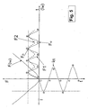
- Fig. 5 in which a Force-current diagram is shown, with a curve F1, which increases with increasing current. Opposite to the direction of force F, the current over time t is shown as sinusoidal curve I 1 . If no shorting ring is provided, then the magnetic force will vary according to the curve F 2 , with the current moving between an upper, maximum value F o and a lower value F u due to the zero crossing, corresponding to the current increase as well as the zero crossing becomes zero. With a short-circuit ring, a force-current curve F 3 is generated in which a decrease in the force to zero is prevented due to the phase-shifted current generated in the ring is prevented.
- the short-circuit ring can be arranged on the magnet armature, on the magnet core or on both.
Landscapes
- Physics & Mathematics (AREA)
- Electromagnetism (AREA)
- Breakers (AREA)
Applications Claiming Priority (1)
| Application Number | Priority Date | Filing Date | Title |
|---|---|---|---|
| DE200610024249 DE102006024249B4 (de) | 2006-05-23 | 2006-05-23 | Leitungsschutzschalter |
Publications (3)
| Publication Number | Publication Date |
|---|---|
| EP1860675A2 true EP1860675A2 (fr) | 2007-11-28 |
| EP1860675A3 EP1860675A3 (fr) | 2009-05-20 |
| EP1860675B1 EP1860675B1 (fr) | 2015-04-22 |
Family
ID=38337823
Family Applications (1)
| Application Number | Title | Priority Date | Filing Date |
|---|---|---|---|
| EP20070008639 Active EP1860675B1 (fr) | 2006-05-23 | 2007-04-27 | Disjoncteur de puissance |
Country Status (2)
| Country | Link |
|---|---|
| EP (1) | EP1860675B1 (fr) |
| DE (1) | DE102006024249B4 (fr) |
Cited By (2)
| Publication number | Priority date | Publication date | Assignee | Title |
|---|---|---|---|---|
| EP2330611A1 (fr) * | 2009-12-04 | 2011-06-08 | HAGER ELECTRO S.A.S. (société par Actions Simplifiée) | Disjoncteur sélectif |
| EP2750158A1 (fr) * | 2012-12-27 | 2014-07-02 | Hager Electro Sas | Sous-ensemble magnétique et thermique pour disjoncteur sélectif |
Families Citing this family (2)
| Publication number | Priority date | Publication date | Assignee | Title |
|---|---|---|---|---|
| DE102008021768B4 (de) | 2007-04-30 | 2023-11-16 | Abb Ag | Elektromagnetischer Auslöser, Verfahren zur Herstellung eines elektromagnetischen Auslösers und Leitungsschutzschalter mit einem elektromagnetischen Auslöser |
| CN102243954A (zh) | 2010-05-12 | 2011-11-16 | Abb股份公司 | 安装开关设备 |
Citations (1)
| Publication number | Priority date | Publication date | Assignee | Title |
|---|---|---|---|---|
| DE3833128A1 (de) | 1988-09-29 | 1990-04-05 | Siemens Ag | Elektromagnetischer ausloeser, insbesondere fuer leitungsschutzschalter |
Family Cites Families (4)
| Publication number | Priority date | Publication date | Assignee | Title |
|---|---|---|---|---|
| DE1764522B2 (de) * | 1968-06-19 | 1973-12-20 | Licentia Patent-Verwaltungs-Gmbh, 6000 Frankfurt | Schaltmagnet für ein elektromagnetisches Schaltgerät |
| CH614069A5 (fr) * | 1977-03-31 | 1979-10-31 | Weber Ag Fab Elektro | |
| DE19809205A1 (de) * | 1998-03-04 | 1999-04-15 | Siemens Ag | Magnetsystem mit Überstromauslösung |
| DE10244961B3 (de) * | 2002-09-26 | 2004-02-12 | Siemens Ag | Selektiver Leitungsschutzschalter |
-
2006
- 2006-05-23 DE DE200610024249 patent/DE102006024249B4/de not_active Expired - Fee Related
-
2007
- 2007-04-27 EP EP20070008639 patent/EP1860675B1/fr active Active
Patent Citations (1)
| Publication number | Priority date | Publication date | Assignee | Title |
|---|---|---|---|---|
| DE3833128A1 (de) | 1988-09-29 | 1990-04-05 | Siemens Ag | Elektromagnetischer ausloeser, insbesondere fuer leitungsschutzschalter |
Cited By (2)
| Publication number | Priority date | Publication date | Assignee | Title |
|---|---|---|---|---|
| EP2330611A1 (fr) * | 2009-12-04 | 2011-06-08 | HAGER ELECTRO S.A.S. (société par Actions Simplifiée) | Disjoncteur sélectif |
| EP2750158A1 (fr) * | 2012-12-27 | 2014-07-02 | Hager Electro Sas | Sous-ensemble magnétique et thermique pour disjoncteur sélectif |
Also Published As
| Publication number | Publication date |
|---|---|
| DE102006024249A1 (de) | 2007-11-29 |
| EP1860675A3 (fr) | 2009-05-20 |
| DE102006024249B4 (de) | 2010-03-25 |
| EP1860675B1 (fr) | 2015-04-22 |
Similar Documents
| Publication | Publication Date | Title |
|---|---|---|
| EP3797438B1 (fr) | Dispositif séparateur pour l'interruption de courant continu d'un chemin de courant et disjoncteur | |
| EP3428942B1 (fr) | Dispositif d'extinction d'arc de courant continu et appareil de commutation de courant continu électromécanique | |
| EP0640242B1 (fr) | Agencement de lames de contact de relais de transmission et de commutation de courants eleves | |
| DE102010035857B4 (de) | Installationsschaltgerät mit einem Magnetsystem | |
| DE112005002227T5 (de) | Elektrische Kontaktgeber | |
| EP1860675B1 (fr) | Disjoncteur de puissance | |
| DE202018006167U1 (de) | Trennvorrichtung zur Gleichstromunterbrechung eines Strompfades sowie Schutzschalter | |
| DE69022077T2 (de) | Auslösesystem für einen elektrischen Schalter und elektrischer Schalter mit diesem Auslösesystem. | |
| EP0793318A1 (fr) | Dispositif dérivateur de surtensions | |
| DE10244961B3 (de) | Selektiver Leitungsschutzschalter | |
| DE102011089251B4 (de) | Auslöseeinheit zum Betätigen einer mechanischen Schalteinheit einer Vorrichtung | |
| DE69206749T2 (de) | Elektrischer Schützschalter mit Einfügung von zusätzlichen Windungen im Magnetauslöser | |
| DE102015119352A1 (de) | Elektromechanischer schutzschalter | |
| DE2756741C2 (de) | Elektrisches Schaltgerät mit elektromagnetischer Kontaktdruckerhöhung | |
| DE102012005031A1 (de) | Installationsschaltgerät | |
| DE102007040164A1 (de) | Schaltgerät mit einem doppelt unterbrechenden Drehkontaktsystem sowie mehrpolige Schaltgeräteanordnung | |
| DE60014122T2 (de) | Lastschalter | |
| DE60003204T2 (de) | Elektrischer pol für einen niederspannungsschutzschalter | |
| DE102019117804B4 (de) | Schalteinrichtung mit einem elektrischen Kontaktsystem | |
| DE19957228B4 (de) | Kontaktanordnung für eine Vakuumschaltkammer | |
| EP3602593B1 (fr) | Appareil de commutation avec extinction d'arc à magnétisme permanent améliorée | |
| DE102012018456A1 (de) | Bimetallanordnung für selektive Schutzschaltgeräte | |
| EP1780740B1 (fr) | Electrovanne pilote pour sectionneur hydromécanique | |
| EP3494585B1 (fr) | Appareil de commutation basse tension comprenant un moyen d'assistance de charge de contact electromagnétique | |
| EP1264322A1 (fr) | Systeme de contacts pour un appareil de coupure a basse tension |
Legal Events
| Date | Code | Title | Description |
|---|---|---|---|
| PUAI | Public reference made under article 153(3) epc to a published international application that has entered the european phase |
Free format text: ORIGINAL CODE: 0009012 |
|
| AK | Designated contracting states |
Kind code of ref document: A2 Designated state(s): AT BE BG CH CY CZ DE DK EE ES FI FR GB GR HU IE IS IT LI LT LU LV MC MT NL PL PT RO SE SI SK TR |
|
| AX | Request for extension of the european patent |
Extension state: AL BA HR MK YU |
|
| PUAL | Search report despatched |
Free format text: ORIGINAL CODE: 0009013 |
|
| AK | Designated contracting states |
Kind code of ref document: A3 Designated state(s): AT BE BG CH CY CZ DE DK EE ES FI FR GB GR HU IE IS IT LI LT LU LV MC MT NL PL PT RO SE SI SK TR |
|
| AX | Request for extension of the european patent |
Extension state: AL BA HR MK RS |
|
| 17P | Request for examination filed |
Effective date: 20091104 |
|
| AKX | Designation fees paid |
Designated state(s): AT BE BG CH CY CZ DE DK EE ES FI FR GB GR HU IE IS IT LI LT LU LV MC MT NL PL PT RO SE SI SK TR |
|
| 17Q | First examination report despatched |
Effective date: 20100211 |
|
| RAP1 | Party data changed (applicant data changed or rights of an application transferred) |
Owner name: ABB AG |
|
| GRAP | Despatch of communication of intention to grant a patent |
Free format text: ORIGINAL CODE: EPIDOSNIGR1 |
|
| INTG | Intention to grant announced |
Effective date: 20150128 |
|
| GRAS | Grant fee paid |
Free format text: ORIGINAL CODE: EPIDOSNIGR3 |
|
| GRAA | (expected) grant |
Free format text: ORIGINAL CODE: 0009210 |
|
| AK | Designated contracting states |
Kind code of ref document: B1 Designated state(s): AT BE BG CH CY CZ DE DK EE ES FI FR GB GR HU IE IS IT LI LT LU LV MC MT NL PL PT RO SE SI SK TR |
|
| REG | Reference to a national code |
Ref country code: GB Ref legal event code: FG4D Free format text: NOT ENGLISH |
|
| REG | Reference to a national code |
Ref country code: CH Ref legal event code: EP |
|
| REG | Reference to a national code |
Ref country code: AT Ref legal event code: REF Ref document number: 723679 Country of ref document: AT Kind code of ref document: T Effective date: 20150515 |
|
| REG | Reference to a national code |
Ref country code: IE Ref legal event code: FG4D Free format text: LANGUAGE OF EP DOCUMENT: GERMAN |
|
| REG | Reference to a national code |
Ref country code: DE Ref legal event code: R096 Ref document number: 502007013877 Country of ref document: DE Effective date: 20150603 |
|
| REG | Reference to a national code |
Ref country code: NL Ref legal event code: VDEP Effective date: 20150422 |
|
| REG | Reference to a national code |
Ref country code: LT Ref legal event code: MG4D |
|
| PG25 | Lapsed in a contracting state [announced via postgrant information from national office to epo] |
Ref country code: NL Free format text: LAPSE BECAUSE OF FAILURE TO SUBMIT A TRANSLATION OF THE DESCRIPTION OR TO PAY THE FEE WITHIN THE PRESCRIBED TIME-LIMIT Effective date: 20150422 |
|
| PG25 | Lapsed in a contracting state [announced via postgrant information from national office to epo] |
Ref country code: ES Free format text: LAPSE BECAUSE OF FAILURE TO SUBMIT A TRANSLATION OF THE DESCRIPTION OR TO PAY THE FEE WITHIN THE PRESCRIBED TIME-LIMIT Effective date: 20150422 Ref country code: LT Free format text: LAPSE BECAUSE OF FAILURE TO SUBMIT A TRANSLATION OF THE DESCRIPTION OR TO PAY THE FEE WITHIN THE PRESCRIBED TIME-LIMIT Effective date: 20150422 Ref country code: FI Free format text: LAPSE BECAUSE OF FAILURE TO SUBMIT A TRANSLATION OF THE DESCRIPTION OR TO PAY THE FEE WITHIN THE PRESCRIBED TIME-LIMIT Effective date: 20150422 Ref country code: PT Free format text: LAPSE BECAUSE OF FAILURE TO SUBMIT A TRANSLATION OF THE DESCRIPTION OR TO PAY THE FEE WITHIN THE PRESCRIBED TIME-LIMIT Effective date: 20150824 |
|
| PG25 | Lapsed in a contracting state [announced via postgrant information from national office to epo] |
Ref country code: GR Free format text: LAPSE BECAUSE OF FAILURE TO SUBMIT A TRANSLATION OF THE DESCRIPTION OR TO PAY THE FEE WITHIN THE PRESCRIBED TIME-LIMIT Effective date: 20150723 Ref country code: LV Free format text: LAPSE BECAUSE OF FAILURE TO SUBMIT A TRANSLATION OF THE DESCRIPTION OR TO PAY THE FEE WITHIN THE PRESCRIBED TIME-LIMIT Effective date: 20150422 Ref country code: IS Free format text: LAPSE BECAUSE OF FAILURE TO SUBMIT A TRANSLATION OF THE DESCRIPTION OR TO PAY THE FEE WITHIN THE PRESCRIBED TIME-LIMIT Effective date: 20150822 |
|
| REG | Reference to a national code |
Ref country code: CH Ref legal event code: PL |
|
| REG | Reference to a national code |
Ref country code: DE Ref legal event code: R097 Ref document number: 502007013877 Country of ref document: DE |
|
| REG | Reference to a national code |
Ref country code: IE Ref legal event code: MM4A |
|
| PG25 | Lapsed in a contracting state [announced via postgrant information from national office to epo] |
Ref country code: CH Free format text: LAPSE BECAUSE OF NON-PAYMENT OF DUE FEES Effective date: 20150430 Ref country code: DK Free format text: LAPSE BECAUSE OF FAILURE TO SUBMIT A TRANSLATION OF THE DESCRIPTION OR TO PAY THE FEE WITHIN THE PRESCRIBED TIME-LIMIT Effective date: 20150422 Ref country code: MC Free format text: LAPSE BECAUSE OF FAILURE TO SUBMIT A TRANSLATION OF THE DESCRIPTION OR TO PAY THE FEE WITHIN THE PRESCRIBED TIME-LIMIT Effective date: 20150422 Ref country code: IT Free format text: LAPSE BECAUSE OF FAILURE TO SUBMIT A TRANSLATION OF THE DESCRIPTION OR TO PAY THE FEE WITHIN THE PRESCRIBED TIME-LIMIT Effective date: 20150422 Ref country code: EE Free format text: LAPSE BECAUSE OF FAILURE TO SUBMIT A TRANSLATION OF THE DESCRIPTION OR TO PAY THE FEE WITHIN THE PRESCRIBED TIME-LIMIT Effective date: 20150422 Ref country code: LI Free format text: LAPSE BECAUSE OF NON-PAYMENT OF DUE FEES Effective date: 20150430 |
|
| PLBE | No opposition filed within time limit |
Free format text: ORIGINAL CODE: 0009261 |
|
| STAA | Information on the status of an ep patent application or granted ep patent |
Free format text: STATUS: NO OPPOSITION FILED WITHIN TIME LIMIT |
|
| PG25 | Lapsed in a contracting state [announced via postgrant information from national office to epo] |
Ref country code: SK Free format text: LAPSE BECAUSE OF FAILURE TO SUBMIT A TRANSLATION OF THE DESCRIPTION OR TO PAY THE FEE WITHIN THE PRESCRIBED TIME-LIMIT Effective date: 20150422 Ref country code: CZ Free format text: LAPSE BECAUSE OF FAILURE TO SUBMIT A TRANSLATION OF THE DESCRIPTION OR TO PAY THE FEE WITHIN THE PRESCRIBED TIME-LIMIT Effective date: 20150422 Ref country code: PL Free format text: LAPSE BECAUSE OF FAILURE TO SUBMIT A TRANSLATION OF THE DESCRIPTION OR TO PAY THE FEE WITHIN THE PRESCRIBED TIME-LIMIT Effective date: 20150422 Ref country code: RO Free format text: LAPSE BECAUSE OF NON-PAYMENT OF DUE FEES Effective date: 20150422 |
|
| GBPC | Gb: european patent ceased through non-payment of renewal fee |
Effective date: 20150722 |
|
| 26N | No opposition filed |
Effective date: 20160125 |
|
| REG | Reference to a national code |
Ref country code: FR Ref legal event code: PLFP Year of fee payment: 10 |
|
| PG25 | Lapsed in a contracting state [announced via postgrant information from national office to epo] |
Ref country code: GB Free format text: LAPSE BECAUSE OF NON-PAYMENT OF DUE FEES Effective date: 20150722 Ref country code: IE Free format text: LAPSE BECAUSE OF NON-PAYMENT OF DUE FEES Effective date: 20150427 |
|
| PG25 | Lapsed in a contracting state [announced via postgrant information from national office to epo] |
Ref country code: SI Free format text: LAPSE BECAUSE OF FAILURE TO SUBMIT A TRANSLATION OF THE DESCRIPTION OR TO PAY THE FEE WITHIN THE PRESCRIBED TIME-LIMIT Effective date: 20150422 |
|
| REG | Reference to a national code |
Ref country code: AT Ref legal event code: MM01 Ref document number: 723679 Country of ref document: AT Kind code of ref document: T Effective date: 20150427 |
|
| PG25 | Lapsed in a contracting state [announced via postgrant information from national office to epo] |
Ref country code: AT Free format text: LAPSE BECAUSE OF NON-PAYMENT OF DUE FEES Effective date: 20150427 |
|
| PG25 | Lapsed in a contracting state [announced via postgrant information from national office to epo] |
Ref country code: MT Free format text: LAPSE BECAUSE OF FAILURE TO SUBMIT A TRANSLATION OF THE DESCRIPTION OR TO PAY THE FEE WITHIN THE PRESCRIBED TIME-LIMIT Effective date: 20150422 |
|
| REG | Reference to a national code |
Ref country code: FR Ref legal event code: PLFP Year of fee payment: 11 |
|
| PG25 | Lapsed in a contracting state [announced via postgrant information from national office to epo] |
Ref country code: BG Free format text: LAPSE BECAUSE OF FAILURE TO SUBMIT A TRANSLATION OF THE DESCRIPTION OR TO PAY THE FEE WITHIN THE PRESCRIBED TIME-LIMIT Effective date: 20150422 Ref country code: HU Free format text: LAPSE BECAUSE OF FAILURE TO SUBMIT A TRANSLATION OF THE DESCRIPTION OR TO PAY THE FEE WITHIN THE PRESCRIBED TIME-LIMIT; INVALID AB INITIO Effective date: 20070427 |
|
| PG25 | Lapsed in a contracting state [announced via postgrant information from national office to epo] |
Ref country code: SE Free format text: LAPSE BECAUSE OF FAILURE TO SUBMIT A TRANSLATION OF THE DESCRIPTION OR TO PAY THE FEE WITHIN THE PRESCRIBED TIME-LIMIT Effective date: 20150422 Ref country code: CY Free format text: LAPSE BECAUSE OF FAILURE TO SUBMIT A TRANSLATION OF THE DESCRIPTION OR TO PAY THE FEE WITHIN THE PRESCRIBED TIME-LIMIT Effective date: 20150422 |
|
| PG25 | Lapsed in a contracting state [announced via postgrant information from national office to epo] |
Ref country code: BE Free format text: LAPSE BECAUSE OF NON-PAYMENT OF DUE FEES Effective date: 20150430 |
|
| PG25 | Lapsed in a contracting state [announced via postgrant information from national office to epo] |
Ref country code: TR Free format text: LAPSE BECAUSE OF FAILURE TO SUBMIT A TRANSLATION OF THE DESCRIPTION OR TO PAY THE FEE WITHIN THE PRESCRIBED TIME-LIMIT Effective date: 20150422 |
|
| PG25 | Lapsed in a contracting state [announced via postgrant information from national office to epo] |
Ref country code: LU Free format text: LAPSE BECAUSE OF NON-PAYMENT OF DUE FEES Effective date: 20150427 |
|
| REG | Reference to a national code |
Ref country code: FR Ref legal event code: PLFP Year of fee payment: 12 |
|
| PGFP | Annual fee paid to national office [announced via postgrant information from national office to epo] |
Ref country code: DE Payment date: 20250422 Year of fee payment: 19 |
|
| PGFP | Annual fee paid to national office [announced via postgrant information from national office to epo] |
Ref country code: FR Payment date: 20250423 Year of fee payment: 19 |