EP1860743A2 - Connecteur de carte et procédé de production d'un assemblage de boîtier - Google Patents
Connecteur de carte et procédé de production d'un assemblage de boîtier Download PDFInfo
- Publication number
- EP1860743A2 EP1860743A2 EP07252050A EP07252050A EP1860743A2 EP 1860743 A2 EP1860743 A2 EP 1860743A2 EP 07252050 A EP07252050 A EP 07252050A EP 07252050 A EP07252050 A EP 07252050A EP 1860743 A2 EP1860743 A2 EP 1860743A2
- Authority
- EP
- European Patent Office
- Prior art keywords
- tray
- card
- housing
- contacts
- metal
- Prior art date
- Legal status (The legal status is an assumption and is not a legal conclusion. Google has not performed a legal analysis and makes no representation as to the accuracy of the status listed.)
- Granted
Links
Images



Classifications
-
- H—ELECTRICITY
- H01—ELECTRIC ELEMENTS
- H01R—ELECTRICALLY-CONDUCTIVE CONNECTIONS; STRUCTURAL ASSOCIATIONS OF A PLURALITY OF MUTUALLY-INSULATED ELECTRICAL CONNECTING ELEMENTS; COUPLING DEVICES; CURRENT COLLECTORS
- H01R13/00—Details of coupling devices of the kinds covered by groups H01R12/70 or H01R24/00 - H01R33/00
- H01R13/648—Protective earth or shield arrangements on coupling devices, e.g. anti-static shielding
- H01R13/658—High frequency shielding arrangements, e.g. against EMI [Electro-Magnetic Interference] or EMP [Electro-Magnetic Pulse]
- H01R13/6581—Shield structure
- H01R13/6582—Shield structure with resilient means for engaging mating connector
-
- G—PHYSICS
- G06—COMPUTING OR CALCULATING; COUNTING
- G06K—GRAPHICAL DATA READING; PRESENTATION OF DATA; RECORD CARRIERS; HANDLING RECORD CARRIERS
- G06K13/00—Conveying record carriers from one station to another, e.g. from stack to punching mechanism
- G06K13/02—Conveying record carriers from one station to another, e.g. from stack to punching mechanism the record carrier having longitudinal dimension comparable with transverse dimension, e.g. punched card
- G06K13/08—Feeding or discharging cards
- G06K13/0806—Feeding or discharging cards using an arrangement for ejection of an inserted card
- G06K13/0831—Feeding or discharging cards using an arrangement for ejection of an inserted card the ejection arrangement comprising a slide, carriage or drawer
-
- G—PHYSICS
- G06—COMPUTING OR CALCULATING; COUNTING
- G06K—GRAPHICAL DATA READING; PRESENTATION OF DATA; RECORD CARRIERS; HANDLING RECORD CARRIERS
- G06K7/00—Methods or arrangements for sensing record carriers, e.g. for reading patterns
- G06K7/0013—Methods or arrangements for sensing record carriers, e.g. for reading patterns by galvanic contacts, e.g. card connectors for ISO-7816 compliant smart cards or memory cards, e.g. SD card readers
- G06K7/0021—Methods or arrangements for sensing record carriers, e.g. for reading patterns by galvanic contacts, e.g. card connectors for ISO-7816 compliant smart cards or memory cards, e.g. SD card readers for reading/sensing record carriers having surface contacts
-
- G—PHYSICS
- G06—COMPUTING OR CALCULATING; COUNTING
- G06K—GRAPHICAL DATA READING; PRESENTATION OF DATA; RECORD CARRIERS; HANDLING RECORD CARRIERS
- G06K7/00—Methods or arrangements for sensing record carriers, e.g. for reading patterns
- G06K7/0013—Methods or arrangements for sensing record carriers, e.g. for reading patterns by galvanic contacts, e.g. card connectors for ISO-7816 compliant smart cards or memory cards, e.g. SD card readers
- G06K7/0034—Methods or arrangements for sensing record carriers, e.g. for reading patterns by galvanic contacts, e.g. card connectors for ISO-7816 compliant smart cards or memory cards, e.g. SD card readers the connector being capable of simultaneously receiving a plurality of cards in the same insertion slot
-
- G—PHYSICS
- G06—COMPUTING OR CALCULATING; COUNTING
- G06K—GRAPHICAL DATA READING; PRESENTATION OF DATA; RECORD CARRIERS; HANDLING RECORD CARRIERS
- G06K7/00—Methods or arrangements for sensing record carriers, e.g. for reading patterns
- G06K7/0013—Methods or arrangements for sensing record carriers, e.g. for reading patterns by galvanic contacts, e.g. card connectors for ISO-7816 compliant smart cards or memory cards, e.g. SD card readers
- G06K7/0056—Methods or arrangements for sensing record carriers, e.g. for reading patterns by galvanic contacts, e.g. card connectors for ISO-7816 compliant smart cards or memory cards, e.g. SD card readers housing of the card connector
- G06K7/0082—Methods or arrangements for sensing record carriers, e.g. for reading patterns by galvanic contacts, e.g. card connectors for ISO-7816 compliant smart cards or memory cards, e.g. SD card readers housing of the card connector comprising an arrangement for protection against electrostatic discharge, e.g. by grounding part of the conductive housing
-
- H—ELECTRICITY
- H01—ELECTRIC ELEMENTS
- H01R—ELECTRICALLY-CONDUCTIVE CONNECTIONS; STRUCTURAL ASSOCIATIONS OF A PLURALITY OF MUTUALLY-INSULATED ELECTRICAL CONNECTING ELEMENTS; COUPLING DEVICES; CURRENT COLLECTORS
- H01R12/00—Structural associations of a plurality of mutually-insulated electrical connecting elements, specially adapted for printed circuits, e.g. printed circuit boards [PCB], flat or ribbon cables, or like generally planar structures, e.g. terminal strips, terminal blocks; Coupling devices specially adapted for printed circuits, flat or ribbon cables, or like generally planar structures; Terminals specially adapted for contact with, or insertion into, printed circuits, flat or ribbon cables, or like generally planar structures
- H01R12/70—Coupling devices
- H01R12/71—Coupling devices for rigid printing circuits or like structures
- H01R12/712—Coupling devices for rigid printing circuits or like structures co-operating with the surface of the printed circuit or with a coupling device exclusively provided on the surface of the printed circuit
- H01R12/714—Coupling devices for rigid printing circuits or like structures co-operating with the surface of the printed circuit or with a coupling device exclusively provided on the surface of the printed circuit with contacts abutting directly the printed circuit; Button contacts therefore provided on the printed circuit
-
- H—ELECTRICITY
- H01—ELECTRIC ELEMENTS
- H01R—ELECTRICALLY-CONDUCTIVE CONNECTIONS; STRUCTURAL ASSOCIATIONS OF A PLURALITY OF MUTUALLY-INSULATED ELECTRICAL CONNECTING ELEMENTS; COUPLING DEVICES; CURRENT COLLECTORS
- H01R43/00—Apparatus or processes specially adapted for manufacturing, assembling, maintaining, or repairing of line connectors or current collectors or for joining electric conductors
- H01R43/20—Apparatus or processes specially adapted for manufacturing, assembling, maintaining, or repairing of line connectors or current collectors or for joining electric conductors for assembling or disassembling contact members with insulating base, case or sleeve
- H01R43/24—Assembling by moulding on contact members
-
- H—ELECTRICITY
- H01—ELECTRIC ELEMENTS
- H01R—ELECTRICALLY-CONDUCTIVE CONNECTIONS; STRUCTURAL ASSOCIATIONS OF A PLURALITY OF MUTUALLY-INSULATED ELECTRICAL CONNECTING ELEMENTS; COUPLING DEVICES; CURRENT COLLECTORS
- H01R43/00—Apparatus or processes specially adapted for manufacturing, assembling, maintaining, or repairing of line connectors or current collectors or for joining electric conductors
- H01R43/16—Apparatus or processes specially adapted for manufacturing, assembling, maintaining, or repairing of line connectors or current collectors or for joining electric conductors for manufacturing contact members, e.g. by punching and by bending
Definitions
- This invention relates to a card connector for use in a various electric and electronic appliances such as mobile phones, personal digital assistants (PDA), printers, card readers and the like for inputting and outputting signals into and from memory cards inserted into the card connector, and to a card connector having a structure achieving a reduced overall height of the card connector and being superior in safety of operation, and more particularly to a method for producing a housing assembly consisting of contacts, metal plates and a housing integrally formed as a unitary structure.
- PDA personal digital assistants
- SD card Secure Digital memory card
- MS card Memory Stick card
- SmartMedia card registered trademark, referred to hereinafter just as "SM card”
- CompactFlash card registered trademark, referred to hereinafter just as "CF card”
- xD card registered trademark, referred to hereinafter just as "xD card”
- Multimedia card registered trademark, referred to hereinafter just as "MM card”
- SIM card Subscriber Identity Module card, registered trademark
- card connectors are disclosed in Japanese Patent Application Opened No. 2003-45,562 (push-push type card connector, Patent Literature 1) and Japanese Patent Application No. 2005-123,252 (Patent Literature 2) and Japanese Patent Application No. 2006-115,165 (Patent Literature 3) both using a tray.
- this invention has an object to provide an IC card inserting and removing device into which an IC card is detachably inserted.
- an IC card inserting and removing device adapted to be incorporated in an electronic appliance, including a housing 100 and a cover 200 covering the housing 100 consisting of a frame portion 110 in the form of a substantially U-shape and a bottom surface 120 closing one side of the frame portion 110 whose opposed lengthwise frame portions 111a and 111b are formed in their inside surfaces with guide grooves 113, and contacts 130 for IC cards arranged in a bottom frame portion 111c, wherein a locking and ejecting mechanism 300 for IC cards is incorporated in one of the lengthwise frame portions 111a and 111b, thereby providing a superior card inserting and removing device which achieves miniaturization and simplification of used parts and enables an IC card to be stably held.
- claim 1 of claims recites an IC card inserting and removing device to be incorporated in an electronic appliance, including a housing and a cover for covering the housing consisting of a frame portion in the form of a substantially U-shape and a bottom portion for reinforcing the frame portion, said frame portion having opposed lengthwise frame portions formed in their inner surfaces with guide grooves for the IC card, and contacts for IC cards arranged in a bottom frame portion perpendicularly crossing said lengthwise frame portions, wherein said device incorporates therein an IC card locking and ejecting mechanism provided on at least one of said lengthwise frame portions comprising a slider advancing and retracting in the same directions of the movements of said IC card upon its insertion and removal, pushing means for always pushing the slider toward the card inserting opening of said guide grooves for the IC card, a cam groove provided in said slider and being in the form of a substantially heart-shape, and a rockable spring pin having a free end engaging in the cam groove and the other end fixed to said bottom
- Claim 2 recites the IC card inserting and removing device as claimed in claim 1, whose slider has an inclined surface portion against which a corner oblique portion of an IC card abuts.
- Claim 3 recites the IC card inserting and removing device as claimed in claim 1 or 2, whose slider is adapted to slidably moved along guide rods provided on said lengthwise frame portions.
- Claim 4 recites the IC card inserting and removing device as claimed in claim 1, 2 or 3, whose lengthwise frame portion not incorporating said IC card locking and ejecting mechanism is provided with a metal fitting having an elastic pressing piece elastically extending in the guide groove for the IC card so as to press the side face of the IC card.
- Claim 5 recites the IC card inserting and removing device as claimed in claim 1, 2 ,3 or 4, whose part of said cover is provided with an elastic pressing piece for pressing the surface of the IC card.
- the object of this invention is to provide a card connector 10 enabling a reduced overall height of the connector with a simple construction, and this object can be achieved by a card connector 10 adapted to be connected to at least two cards 60 and including contacts 14 corresponding to the number of the cards 60, a tray 16 in which at least two cards 60 can be loaded, and a housing having a fitting opening 20 for receiving the tray 16 and arranging and holding said contacts 14.
- a card connector 10 adapted to be connected to four cards 60
- a card connector including contacts 14 of four kinds, a tray 16 having a card loading portion 22 into which the four cards 60 can be loaded, and a housing 12 for arranging and holding the contacts 14 of four kinds and having a fitting opening 20 for receiving the tray 16.
- claim 1 recites a card connector being connected to at least two cards, comprising contacts corresponding to the number of said cards, a tray into which at least two cards can be loaded, and a housing having a fitting opening for receiving said tray and arranging and holding said contacts.
- Claim 2 recites a card connector being connected to four cards, comprising contacts of four kinds, a tray having a card loading portion into which the four cards can be loaded, and a housing for arranging and holding said contacts of four kinds and having a fitting opening for receiving said tray.
- Claim 3 recites the card connector as claimed in claim 1 or 2, wherein said tray is provided with the card loading portion having one part overlapping in relation to kinds of card other than one kind of card intended to be loaded in the card loading portion so as to allow the intended one kind of card only to be loaded in the card loading portion.
- Claim 4 recites the card connector as claimed in claim 1 or 2, wherein said tray is provided with the card loading portion not having a part overlapping in relation to at least two kinds of cards so as to allow at least two kinds of cards to be loaded in the card loading portion and said tray is further provided with a card identification mechanism for identifying the cards to be used.
- Claim 5 recites the card connector as claimed in claim 1,2,3 or 4, wherein said housing is provided with stopper means on the side of the fitting opening for preventing the tray from extending from the housing.
- Claim 6 recites the card connector as claimed in any one of claims 1 to 5, further comprising a mechanism for drawing said tray to some extent relative to the housing by pushing said tray in the state that said tray has been inserted.
- this invention has an object to provide a card connector which is miniaturized and lighter, more compact and simple in construction and is easy to remove a memory card.
- a card connector 10 into and from which a memory card 60 is detachably inserted and removed, including contacts 14 each adapted to contact a connection portion of the memory card 60, and a housing 12 for arranging and holding the contacts 14 and having an inserting opening 22 for inserting the memory card 60, wherein the housing 12 includes two side walls 24, a rear wall 26, and a lower wall 28 contiguous to these side and rear walls 24 and 26 to form the inserting opening 22 for the memory card 60 by these walls 24, 26 and 28, and a shell 16 is arranged on the side of the housing opposite from the lower wall 28, and an elastically deformable tray 18 is arranged on the lower wall 28 so as to be slidable with the aid of a tray restraining plate 20.
- claim 1 recites a card connector into and from which a memory card is detachably inserted and removed, including contacts each adapted to contact a connection portion of the memory card, and a housing for arranging and holding said contacts and having an inserting opening for inserting the memory card, wherein said housing comprises two side walls, a rear wall, and a lower wall contiguous to these side and rear walls to form said inserting opening for said memory card by the two side walls, the rear wall, and the lower wall, and wherein a shell is arranged on the side of the housing opposite from said lower wall, and an elastically deformable tray is arranged on said lower wall so as to be slidable with the aid of a tray restraining plate.
- Claim 2 recites the card connector as claimed in claim 1, wherein said tray is made of a metal having an elasticity in the form of a plate and comprises at one free end an operating portion extending from the end face of said lower wall when said memory card has been loaded so that said tray is slidably moved by drawing said operating portion.
- Claim 3 recites the card connector as claimed in claim 1 or 2, wherein said tray comprises erroneous fitting preventing means and positioning means for said memory card.
- Claim 4 recites the card connector as claimed in any one of claims 1 to 3, wherein said tray is formed as a plate-shaped piece so that a space is provided below the lower surface of said memory card when said tray has been drawn from the housing.
- a card connector 10 into and from which a memory card 60 is detachably inserted and removed, including contacts 14 adapted to contact connection portions of the memory card 60, and a housing 12 for arranging and holding said contacts 14, wherein metal plates 16 made of a metal are mounted in said housing 12 so as to extend onto both sides in the width direction of the housing 12, said metal plates 16 integrally provided with connection portions 163 to be connected to a substrate, and a tray 18 made of a metal is provided for loading a plurality of memory cards 60 therein, either of both ends of said tray 18 in its width direction being bent substantially into an L-shape, which bent portion 26 slidably engages said metal plate 16.
- a card connector 10 into and from which a memory card 60 is detachably inserted and removed, including contacts 14 adapted to contact connection portions of the memory card 60, and a housing 12 for arranging and holding said contacts 14, wherein said housing 12 is provided with extending portions 24 extending onto both sides in its width direction, and a tray 18 made of a metal is provided for loading one memory card 60 therein, either of both ends of said tray 18 in its width direction being bent substantially into an L-shape, which bent portion 26 slidably engages said extending portion 24.
- the extending portions 24 of said housing 12 are made of metal plates 16 separate from said housing 12, and said metal plates 16 are integrally provided with connection portions 163 to be connected to a substrate.
- said tray 18 is attached with a button 22 made of a resin mounted thereon on either of both sides in the width direction and at the other end opposite to the end bent into the L-shape.
- said metal plates 16 or said extending portions 24 are provided with projections 30 on the side of insertion of the tray on both sides in the width direction, respectively, and said tray 18 is provided on its side faces 34 with anchoring grooves 28, respectively, with which said projections 30 are in slidable engagement.
- a housing assembly 20 is used which is integrally formed with said contacts 14 and said metal plates 16.
- said side faces 34 of said tray 18 on both the sides in the width direction are provided at their free ends with folded-back portions 38, respectively.
- a method for producing said housing assembly 20 comprises successively performing steps of forming a subassembly 21 by press-working said contacts 14 and said metal plate 16 into an integral predetermined shape as a first step, integrally molding said housing 12 with the subassembly 21 formed in the first step after the subassembly 21 has been set in a metal mold as a second step, and cutting connecting portions between said contacts 14 and said metal plate 16 of the integrally molded product in said second step, as a third step.
- the card connector and the method for producing a housing assembly according to the invention bring about the following significant functions and effects.
- the extending portions 24 of said housing 12 are made of metal plates 16 separate from said housing 12, and said metal plates 16 are integrally provided with connection portions 163 to be connected to a substrate. Therefore, it is possible to achieve a reduced overall height of the card connector of less than 2 mm, and shielding, and preparation for static electricity can be easily performed by merely inserting a memory card into the card connector.
- said tray 18 is provided with a button 22 made of a resin mounted thereon on either of both sides in the width direction and at the other end opposite to the end bent into the L-shape. Accordingly, said tray 18 can be safely handled.
- said metal plates 16 or said extending portions 24 are provided with projections 30 on the side of insertion of the tray on both sides in the width direction, respectively, and said tray 18 is provided on its side faces 34 with anchoring grooves 28, respectively, with which said projections 30 are in slidable engagement. Consequently, the engagement of the projections 30 with said anchoring grooves 28 not only provides an effective guide at the sliding movement of the tray to keep it in a stable condition, but also serves to limit the movement of the tray 18.
- a housing assembly 20 is used which is integrally formed with said contacts 14 and said metal plates 16. Therefore, it is possible to achieve a reduced overall height of the card connector of less than 2 mm.
- said side faces 34 of said tray 18 on both the sides in the width direction are provided at their free ends with folded-back portions 38, respectively. Consequently, fingers are completely prevented from being injured even if a person directly contacts said tray 18 made of a metal.
- a method for producing said housing assembly 20 comprises successively performing steps of forming a subassembly 21 by press-working said contacts 14 and said metal plate 16 into an integral predetermined shape as a first step, integrally molding said housing 12 with the subassembly 21 formed in the first step after the subassembly 21 has been set in a metal mold as a second step, and cutting connecting portions between said contacts 14 and said metal plate 16 of the integrally molded product in said second step, as a third step. Therefore, this method can produce said housing assembly 20 in a simple manner and leads to a reduced overall height of the card connector of less than 2 mm.
- Figure 1A is a perspective view of the card connector with a tray drawn, viewed from the fitting side
- Figure 1B is a perspective view of the card connector with the tray inserted, viewed from the fitting side
- Figure 2A is a perspective view of the card connector with the tray drawn and a card loaded, viewed from the fitting side
- Figure 2B is a perspective view of the card connector with the tray inserted together with the card loaded therein, viewed from the fitting side
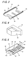
- Figure 3 is a perspective view of the tray.
- Figure 4 is a perspective view of a button.
- Figure 5 is a perspective view of a housing integrally holding contacts and a metal plate.
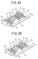
- Figure 6A is a perspective view of the contacts and a metal plate formed as one or integral unit
- Figure 6B is a perspective view of the contacts and the metal plates, separated.
- Figure 7A is a perspective view of a tray different from the tray shown in Figure 3, with the button installed thereon
- Figure 7B is a partly enlarged view of the encircled portion A in Figure 7A.
- the card connector 10 of one embodiment according to the invention mainly comprises a housing assembly 20 (a housing integrally molded with integrally formed contacts 14 and metal plates 16), a tray 18, and a button 22.
- Said cards are used for printers, card readers and the like.
- Said cards each mainly comprise contact portions adapted to contact the contact portions 141 of the contacts 14, patterns connecting from the contact portions of the card to circuits, and connection portions adapted to be connected to integrated circuits and central processing units mounted on the patterns.
- Cards to be used for the card connector 10 according to the invention include SIM card (Subscriber Identity Module card, registered trademark), Multimedia card (registered trademark), SD card (Secure Digital memory card, registered trademark), Mini-SD card (Mini Secure Digital memory card, registered trademark), Memory Stick card (registered trademark), SmartMedia card (registered trademark), CompactFlash card (registered trademark), xD card (registered trademark), RS-MMC card (Reduce Size MMC card, registered trademark), Transflash card (registered trademark), S card (registered trademark), Memory-stick Duo card (registered trademark) and the like.
- SIM card Subscriber Identity Module card, registered trademark
- Multimedia card registered trademark
- SD card Secure Digital memory card, registered trademark
- Mini-SD card Mini Secure Digital memory card, registered trademark
- Memory Stick card registered trademark
- SmartMedia card registered trademark
- CompactFlash card registered trademark
- xD card registered trademark
- RS-MMC card Reduce Size MMC card, registered trademark
- Transflash card registered trademark
- the card connector 10 of the illustrated embodiment is so constructed that the SIM card (registered trademark) can be inserted.
- the method for producing the housing assembly 20 will be explained at the beginning, which is essential for achieving a reduced overall height of the connector.
- the method for producing the housing assembly 20 may be effected by successively performing the following first to third steps.
- said contacts 14 and said metal plates 16 are formed from a metal plate by press-working to an integral or unitary predetermined shape, thereby forming a subassembly 21 as shown in Figure 6A.
- a housing is integrally molded in the metal mold together with the subassembly 21 to form a housing assembly 20.
- the subassembly 21 is made of a metal and formed by means of the press-working of the known technique.
- Preferred metals from which to form said subassembly 21 include brass, beryllium copper, phosphor bronze and the like which comply with the requirements as to electric conductivity, dimensional stability, formability, springiness, and the like.
- Said contacts 14 each mainly comprise a contact portion 141 adapted to contact a connection portion of a memory card, and a connection portion 143 to be connected to a substrate.
- Said contacts 14 are commensurate with the SIM card (registered trademark) 60, and the connection portions of the contacts 14 may be suitably designed in consideration of circuit design and occupied area of the substrate, and size and design of the connector 10.
- the contacts 14 are arranged such that their connection portions 143 extend in both the directions, that is, in the inserting direction of the tray and in the opposite direction thereto.
- the connection portions 143 are of a surface mounting type (SMT) as shown in Figures 1A and 1B.
- SMT surface mounting type
- the contact portion 141 of the contact 14 is curved so as to come into contact with the inserted memory card 60 with ease.
- the position of the contact portion 141 may be suitably designed in consideration of the respective position of the connection portion of the inserted memory card 60.
- the size of the curved portion of the contact portion 141 may be suitably designed in consideration of the contact pressure on the memory card 60.
- Said metal plates 16 each mainly comprise an extending portion 24 extending in the width direction of said housing 12, and connection portions 163 to be connected to the substrate. Said metal plates 16 have functions of shielding and discharging any static electricity when contacting the tray.
- the connection portions 163 of said metal plates 16 may be suitably designed in consideration of the circuit design and occupied area of the substrate and the size and design of the connector 10. In the illustrated embodiment, said metal plates 16 are arranged such that their connection portions 163 extend in both the inserting direction of said tray and the direction opposite thereto.
- the connection portions 163 are of a surface mounting type (SMT) as shown in Figures 1A and 1B.
- the subassembly 21 is formed by integrally or unitarily forming said contacts 14 and said metal plates 16.
- said subassembly 21 consists of the six contacts 14 and two metal plates 16.
- said extending portions 24 are formed by said metal plates 16 in the illustrated embodiment, said extending portions 24 may be formed by the metal plate 16 and said housing 12 (said metal plates 16 may be arranged above the housing as the case may be), or said extending portions 24 may be formed only by said housing 12 without using the metal plates 16.
- Said extending portions 24 are each provided with a projection 30 on the side of the insertion of the tray so that the projections 30 extend on both the sides in the width direction.
- Said projections 30 engage anchoring grooves 28 provided on side faces 34 of said tray 18.
- the engagement of said projections 30 with said anchoring grooves 28 not only provides a guide for stable sliding movement of the tray, but also serves to limit the movement of the tray.
- said tray 18 is being drawn by a strong force, under the influence of which the tray 18 may often jump out of its course. Such a risk can be avoided by the engagement of the projections 30 with the anchoring grooves 28.
- the size of said projections 30 may be suitably designed in consideration of the strength, slidability and the like of said tray 18.
- the housing is molded in the metal mold so that the housing is integrally molded with said subassembly 21, thereby forming the housing assembly 20.
- said contacts 14, said metal plates 16, and the housing 12 are formed into an integral or unitary body.
- the insulator portion (housing 12) is formed from an electrically insulating plastic material by means of the injection molding of the known technique.
- the materials for the insulator portion may be suitably selected in consideration of dimensional stability, workability, manufacturing cost, and the like and generally include polybutylene terephthalate (PBT), polyamide (66PA or 46PA), liquid crystal polymer (LCP), polycarbonate (PC) and the like and combination thereof.
- PBT polybutylene terephthalate
- 66PA or 46PA polyamide
- LCP liquid crystal polymer
- PC polycarbonate
- the housing assembly 20 as a final product is formed with the holes 32 for electrically disconnecting between said contacts 14 and said metal plate 16.
- Said holes 32 are formed by drilling said housing assembly 20 set in a predetermined metal die, thereby electrically disconnecting said contacts 14 from said metal plate 16.
- the positions of said holes 32 correspond to the connection portions between the contacts 14 and said metal plates 16.
- the tray 18 will then be explained, which is one important aspect of the invention.
- the tray 18 is made of a metal in the illustrated embodiment, and formed by means of the press-working of the known technique.
- Preferred metals from which to form said tray 18 include brass, beryllium copper, phosphor bronze and the like which comply with the requirements as to electric conductivity, dimensional stability, formability, springiness, and the like.
- Said tray 18 serves to hold the memory card, and to insert and remove the memory card into and from the card connector 10 by inserting and removing the tray 18 into and from said housing assembly 20.
- Said tray 18 has a substantially U-shaped cross-section and includes bent portions 26 at both ends in its width direction.
- the bent portions 26 are bent in the direction opposite to the inserting direction of the tray 18.
- Said bent portions 28 are adapted to contact and engage the extending portions 24 of said housing assembly 20, respectively, so as to slide on said extending portions 24.
- the shape of said bent portions 26 need only be able to contact the extending portions 24 and slide thereon and may be suitably designed in consideration of strength, slidability, conductivity, workability and the like.
- the side faces 34 of said tray 18 are each provided with the anchoring groove 28 adapted to engage said projection 30.
- the engagement of said projections 30 with said anchoring grooves 28 not only provides a guide for stable sliding movement of the tray, but also serves to limit the movement of the tray.
- said tray 18 is being drawn by a strong force, under the influence of which the tray 18 may often jump out of its course. Such a risk can be avoided by the engagement of the projections 30 with the anchoring grooves 28.
- Said anchoring grooves 28 extend substantially over the full length of the side faces 34, respectively.
- the size of said anchoring grooves 28 may be suitably designed in consideration of the strength, slidability and the like of said tray 18.
- the tray 18 is for loading said memory card 60 therein, the tray 18 is provided with the upright portions surrounding said memory card, such as said side faces 34.
- folded-back portions 38 In order to prevent fingers of a person from being injured upon the fingers touching said tray made of a metal, moreover, it is preferable to provide folded-back portions 38 at free ends of said side faces 34 of said tray 18 on both the sides in its width direction as shown in Figures 7A and 7B.
- the folded-back portions 38 must necessarily be provided so as not to adversely affect the sliding movement of the tray on said housing assembly 20.
- the volume of the folded-back portions 38 need only fulfill the above requirements, and the free ends of the upright portions need only be folded back in any way without any facture surfaces remained.
- the shape and size of the folded-back portions may be suitably designed so as to fulfill the above requirements. In the illustrated embodiment, there are provided the folded-back portions of the order of 0.05 to 0.1 mm.
- a tray 18 in which a plurality of memory cards are loaded will be explained herein. Differences from the tray 18 (in which a single memory card is loaded described above) only will be described. It is required to separate memory cards from one another by insulators in order to load the plurality of memory cards in a tray. Therefore, partition members made of an insulating material are fixed to a tray 18 by press-fitting, welding, or the like. The partition members may be suitably designed depending upon sizes of memory cards to be loaded. The thickness of the partition members between the cards is of the order of 0.5 mm.
- partition members In view of manufacturing efficiency, strength of the partition members, management cost, it is desirable to form the partition members together with a button 22 described below and the metal tray 18 as an integral or unitary member.
- Said button 22 is formed from an electrically insulating plastic material by means of the injection molding of the known technique.
- the materials for the button 22 may be suitably selected in consideration of dimensional stability, workability, manufacturing cost, and the like and generally include polybutylene terephthalate (PBT), polyamide (66PA or 46PA), liquid crystal polymer (LCP), polycarbonate (PC) and the like and combination thereof.
- Said button 22 serves to protect a person handling said tray 18 from being injured by the tray 18 made of a metal. Moreover, said button 22 is provided with an inclined portion 36 which prevent an erroneous fitting of a memory card or a wrong memory card from being inserted. Position and shape of the button 22 are suitably designed in consideration of easy handling, erroneous fitting prevention, and the like. In the illustrated embodiment, the button 22 is provided on one end of said tray 18 opposite to the end provided with the bent portion 26. The button 26 is fixed to the tray by press-fitting, welding, integral forming, or the like.
- the card connector 10 has been shown and explained, having the structure into which the SIM card (registered trademark) 60 can be inserted, needless to say, constructions similar to that described above according to the invention are also applicable to connectors for memory cards other than the SIM card.
- Examples of applications of the present invention include card connectors being capable of exchanging signals between the connector and a memory card inserted therein for use in various electric and electronic appliances such as mobile phones, personal digital assistants (PDA), printers, card readers and the like, and particularly card connectors with a structure which achieves a reduced overall height of the connector and is superior in safe operationality.
- PDA personal digital assistants
- card connectors with a structure which achieves a reduced overall height of the connector and is superior in safe operationality.
Landscapes
- Engineering & Computer Science (AREA)
- Physics & Mathematics (AREA)
- General Physics & Mathematics (AREA)
- Theoretical Computer Science (AREA)
- Artificial Intelligence (AREA)
- Computer Vision & Pattern Recognition (AREA)
- Manufacturing & Machinery (AREA)
- Coupling Device And Connection With Printed Circuit (AREA)
- Details Of Connecting Devices For Male And Female Coupling (AREA)
- Manufacturing Of Electrical Connectors (AREA)
Applications Claiming Priority (2)
| Application Number | Priority Date | Filing Date | Title |
|---|---|---|---|
| JP2006145421 | 2006-05-25 | ||
| JP2006345308A JP5049003B2 (ja) | 2006-05-25 | 2006-12-22 | カードコネクタ及びハウジングSubAssyの製造方法 |
Publications (3)
| Publication Number | Publication Date |
|---|---|
| EP1860743A2 true EP1860743A2 (fr) | 2007-11-28 |
| EP1860743A3 EP1860743A3 (fr) | 2011-01-05 |
| EP1860743B1 EP1860743B1 (fr) | 2012-08-15 |
Family
ID=38226678
Family Applications (1)
| Application Number | Title | Priority Date | Filing Date |
|---|---|---|---|
| EP07252050A Not-in-force EP1860743B1 (fr) | 2006-05-25 | 2007-05-18 | Connecteur de carte et procédé de production d'un assemblage de boîtier |
Country Status (3)
| Country | Link |
|---|---|
| US (2) | US7540782B2 (fr) |
| EP (1) | EP1860743B1 (fr) |
| JP (1) | JP5049003B2 (fr) |
Families Citing this family (20)
| Publication number | Priority date | Publication date | Assignee | Title |
|---|---|---|---|---|
| US8206168B2 (en) * | 2007-01-19 | 2012-06-26 | Molex Incorporated | Terminal assemblies, connectors and manufacturing thereof |
| KR101496458B1 (ko) * | 2008-03-26 | 2015-02-26 | 타이코에이엠피(유) | 심 카드의 커넥터 |
| CN201285850Y (zh) * | 2008-09-09 | 2009-08-05 | 富士康(昆山)电脑接插件有限公司 | 电连接器 |
| US7824225B1 (en) * | 2009-06-11 | 2010-11-02 | Cheng Uei Precision Industry Co., Ltd. | Electrical connector having terminals insert molded to a base board |
| WO2011051811A1 (fr) * | 2009-10-27 | 2011-05-05 | Fci | Connecteur pour carte sim, avec dispositif de retenue de carte |
| JP5457888B2 (ja) * | 2010-03-04 | 2014-04-02 | 第一電子工業株式会社 | カードコネクタ及びカードコネクタの製造方法 |
| KR101314636B1 (ko) | 2012-03-05 | 2013-10-14 | (주)우주일렉트로닉스 | 커넥터 커버의 제조방법 |
| CN202712528U (zh) * | 2012-06-05 | 2013-01-30 | 番禺得意精密电子工业有限公司 | 电连接器 |
| JP5835239B2 (ja) * | 2013-01-08 | 2015-12-24 | 山一電機株式会社 | トレイ型カードコネクタ |
| JP6342219B2 (ja) * | 2014-05-27 | 2018-06-13 | 株式会社東芝 | Icカード用基材、及び嵌込icカード |
| CN105337064B (zh) * | 2014-07-11 | 2018-07-06 | 富士康(昆山)电脑接插件有限公司 | 电子卡连接器 |
| US9590331B2 (en) * | 2014-10-28 | 2017-03-07 | Kabushiki Kaisha Toshiba | Card connector |
| US10038268B2 (en) * | 2015-06-05 | 2018-07-31 | Foxconn Interconnect Technology Limited | Electrical connector having improved contact module and method for making same |
| US10135204B2 (en) * | 2015-06-05 | 2018-11-20 | Foxconn Interconnect Technology Limited | Electrical connector having an auxiliary contact |
| JP1552812S (fr) * | 2015-11-03 | 2016-06-27 | ||
| JP1553611S (fr) * | 2015-11-03 | 2016-07-11 | ||
| JP1553879S (fr) * | 2015-11-03 | 2016-07-11 | ||
| JP1552814S (fr) * | 2015-11-04 | 2016-06-27 | ||
| JP1552813S (fr) * | 2015-11-04 | 2016-06-27 | ||
| JP1552815S (fr) * | 2015-11-06 | 2016-06-27 |
Citations (4)
| Publication number | Priority date | Publication date | Assignee | Title |
|---|---|---|---|---|
| WO2004047228A1 (fr) | 2002-11-19 | 2004-06-03 | Molex Incorporated | Connecteur de carte memoire ameliore |
| US20040161965A1 (en) | 1999-07-23 | 2004-08-19 | Bricaud Herve?Apos; Guy | Smart card with lock sensing switch |
| US6805570B1 (en) | 2003-10-08 | 2004-10-19 | Super Link Electronics Co., Ltd. | Subscriber identity module connector with cover board grounding structure |
| US20060038012A1 (en) | 2004-08-19 | 2006-02-23 | J.S.T. Mfg. Co., Ltd. | Socket for memory card |
Family Cites Families (25)
| Publication number | Priority date | Publication date | Assignee | Title |
|---|---|---|---|---|
| JP2555052B2 (ja) * | 1987-03-02 | 1996-11-20 | 古河電気工業株式会社 | 電気接続箱の製造方法 |
| SG44631A1 (en) * | 1993-05-13 | 1997-12-19 | Molex Inc | IC pack connector apparatus with switch means |
| FR2742561B1 (fr) * | 1995-12-13 | 1998-01-09 | Itt Composants Instr | Connecteur electrique pour une carte a circuit(s) integre(s) a contact |
| US6095868A (en) * | 1997-03-21 | 2000-08-01 | The Whitaker Corporation | Card reader connector having a separable cover |
| DE19741466A1 (de) * | 1997-09-19 | 1999-04-15 | Framatome Connectors Int | Verfahren zur Herstellung eines in ein Gerätegehäuse eingießbaren Flachsteckerkamms |
| JPH11297415A (ja) * | 1998-04-03 | 1999-10-29 | Molex Inc | カード用コネクタ |
| EP0977139B1 (fr) * | 1998-07-30 | 2000-09-27 | Molex Incorporated | Connecteur pour carte à puce |
| JP3307883B2 (ja) * | 1998-09-22 | 2002-07-24 | ホシデン株式会社 | カードコネクタ |
| TW474466U (en) * | 2000-06-03 | 2002-01-21 | Hon Hai Prec Ind Co Ltd | Electronic card connector |
| US6261113B1 (en) * | 2000-11-10 | 2001-07-17 | Hon Hai Precision Ind, Co., Ltd. | Electrical connector having improved arrangement of terminals |
| US6764336B2 (en) * | 2001-02-27 | 2004-07-20 | Hon Hai Precision Ind. Co., Ltd. | Method for forming an electrical connector and an electrical connector obtained thereby |
| JP3927004B2 (ja) | 2001-08-02 | 2007-06-06 | 第一電子工業株式会社 | Icカードの挿脱装置 |
| JP2003243092A (ja) * | 2002-02-18 | 2003-08-29 | Matsushita Electric Works Ltd | メモリカード用ソケット |
| JP3965080B2 (ja) * | 2002-05-31 | 2007-08-22 | 日本圧着端子製造株式会社 | メモリーカード用コネクタおよびそれを備えた携帯電話 |
| JP4238013B2 (ja) * | 2002-11-05 | 2009-03-11 | アルプス電気株式会社 | カード用コネクタ装置 |
| JP4121417B2 (ja) * | 2003-04-24 | 2008-07-23 | ケル株式会社 | カードコネクタ |
| KR100644784B1 (ko) * | 2003-07-07 | 2006-11-15 | 마츠시타 덴끼 산교 가부시키가이샤 | Pc 카드 |
| TWM244598U (en) * | 2003-09-26 | 2004-09-21 | Molex Taiwan Ltd | SIM card connector |
| JP4403040B2 (ja) * | 2004-08-19 | 2010-01-20 | 日本圧着端子製造株式会社 | Simソケット用カードホルダー |
| JP2006115165A (ja) | 2004-10-14 | 2006-04-27 | Mitsubishi Electric Corp | 通信装置および通信システム |
| CN2737003Y (zh) * | 2004-10-27 | 2005-10-26 | 富士康(昆山)电脑接插件有限公司 | 电连接器 |
| CN100546104C (zh) * | 2005-03-04 | 2009-09-30 | 日本电气株式会社 | 卡连接器和电子设备 |
| JP2006302684A (ja) | 2005-04-21 | 2006-11-02 | D D K Ltd | カードコネクタ |
| US7112075B1 (en) * | 2006-02-08 | 2006-09-26 | Cheng Uei Precision Industry Co., Ltd. | Drawer SIM card connector |
| US7118419B1 (en) * | 2006-04-04 | 2006-10-10 | Cheng Uei Precision Industry Co., Ltd. | Foldable SIM card connector |
-
2006
- 2006-12-22 JP JP2006345308A patent/JP5049003B2/ja not_active Expired - Fee Related
-
2007
- 2007-05-10 US US11/746,881 patent/US7540782B2/en not_active Expired - Fee Related
- 2007-05-18 EP EP07252050A patent/EP1860743B1/fr not_active Not-in-force
-
2008
- 2008-07-11 US US12/172,012 patent/US20080274648A1/en not_active Abandoned
Patent Citations (4)
| Publication number | Priority date | Publication date | Assignee | Title |
|---|---|---|---|---|
| US20040161965A1 (en) | 1999-07-23 | 2004-08-19 | Bricaud Herve?Apos; Guy | Smart card with lock sensing switch |
| WO2004047228A1 (fr) | 2002-11-19 | 2004-06-03 | Molex Incorporated | Connecteur de carte memoire ameliore |
| US6805570B1 (en) | 2003-10-08 | 2004-10-19 | Super Link Electronics Co., Ltd. | Subscriber identity module connector with cover board grounding structure |
| US20060038012A1 (en) | 2004-08-19 | 2006-02-23 | J.S.T. Mfg. Co., Ltd. | Socket for memory card |
Also Published As
| Publication number | Publication date |
|---|---|
| US20080274648A1 (en) | 2008-11-06 |
| EP1860743B1 (fr) | 2012-08-15 |
| JP5049003B2 (ja) | 2012-10-17 |
| US20070275601A1 (en) | 2007-11-29 |
| JP2008004523A (ja) | 2008-01-10 |
| EP1860743A3 (fr) | 2011-01-05 |
| US7540782B2 (en) | 2009-06-02 |
Similar Documents
| Publication | Publication Date | Title |
|---|---|---|
| EP1860743B1 (fr) | Connecteur de carte et procédé de production d'un assemblage de boîtier | |
| US7427206B2 (en) | Card connector | |
| US6402529B2 (en) | Card connector | |
| US6669494B2 (en) | Card connector having improved stopper for eject mechanism | |
| US8740634B2 (en) | Card connector | |
| EP2330689A1 (fr) | Connecteur de carte a circuit integre | |
| KR20010007014A (ko) | 카드접속용 아댑터 | |
| JP2006302684A (ja) | カードコネクタ | |
| JP2001357931A (ja) | カードコネクタ | |
| US7794232B2 (en) | Card connector and electronic device | |
| EP1678662B1 (fr) | Connecteur de carte memoire equipe d'un mecanisme d'ejection de carte | |
| US6839431B2 (en) | Card connector | |
| US20070218770A1 (en) | Card connector | |
| US7452241B2 (en) | Card connector | |
| CN100585952C (zh) | 卡连接器和用于生产机架组件的方法 | |
| KR101057236B1 (ko) | 카드 커넥터 | |
| US8277238B2 (en) | Card connector | |
| JP2012113984A (ja) | カード用コネクタ | |
| US7351079B2 (en) | Card connector | |
| US7258578B2 (en) | Card connector with locking mechanism | |
| JP4272939B2 (ja) | カード用コネクタ | |
| KR101076652B1 (ko) | 커넥터 및 검출 스위치 | |
| JP2008204847A (ja) | カードコネクタ装置 |
Legal Events
| Date | Code | Title | Description |
|---|---|---|---|
| PUAI | Public reference made under article 153(3) epc to a published international application that has entered the european phase |
Free format text: ORIGINAL CODE: 0009012 |
|
| 17P | Request for examination filed |
Effective date: 20070518 |
|
| AK | Designated contracting states |
Kind code of ref document: A2 Designated state(s): AT BE BG CH CY CZ DE DK EE ES FI FR GB GR HU IE IS IT LI LT LU LV MC MT NL PL PT RO SE SI SK TR |
|
| AX | Request for extension of the european patent |
Extension state: AL BA HR MK YU |
|
| PUAL | Search report despatched |
Free format text: ORIGINAL CODE: 0009013 |
|
| AK | Designated contracting states |
Kind code of ref document: A3 Designated state(s): AT BE BG CH CY CZ DE DK EE ES FI FR GB GR HU IE IS IT LI LT LU LV MC MT NL PL PT RO SE SI SK TR |
|
| AX | Request for extension of the european patent |
Extension state: AL BA HR MK RS |
|
| RIC1 | Information provided on ipc code assigned before grant |
Ipc: H01R 13/24 20060101ALN20070717BHEP Ipc: H01R 43/24 20060101ALI20101126BHEP Ipc: H01R 13/658 20110101ALI20101126BHEP Ipc: H01R 13/648 20060101ALI20101126BHEP Ipc: H01R 13/506 20060101AFI20070717BHEP |
|
| AKX | Designation fees paid |
Designated state(s): AT BE BG CH CY CZ DE DK EE ES FI FR GB GR HU IE IS IT LI LT LU LV MC MT NL PL PT RO SE SI SK TR |
|
| GRAP | Despatch of communication of intention to grant a patent |
Free format text: ORIGINAL CODE: EPIDOSNIGR1 |
|
| RIC1 | Information provided on ipc code assigned before grant |
Ipc: H01R 13/658 20110101ALI20120216BHEP Ipc: H01R 43/24 20060101ALI20120216BHEP Ipc: H01R 12/71 20110101ALI20120216BHEP Ipc: H01R 13/6582 20110101ALI20120216BHEP Ipc: G06K 7/00 20060101ALI20120216BHEP Ipc: H01R 13/506 20060101AFI20120216BHEP Ipc: H01R 13/648 20060101ALI20120216BHEP Ipc: H01R 13/24 20060101ALN20120216BHEP |
|
| RIC1 | Information provided on ipc code assigned before grant |
Ipc: G06K 7/00 20060101ALI20120220BHEP Ipc: H01R 13/6582 20110101ALI20120220BHEP Ipc: H01R 12/71 20110101ALI20120220BHEP Ipc: H01R 13/658 20110101ALI20120220BHEP Ipc: H01R 43/24 20060101ALI20120220BHEP Ipc: H01R 13/24 20060101ALN20120220BHEP Ipc: H01R 13/648 20060101ALI20120220BHEP Ipc: H01R 13/506 20060101AFI20120220BHEP |
|
| RIN1 | Information on inventor provided before grant (corrected) |
Inventor name: TAKEI, KAZUNORI Inventor name: TAKAHASHI, HIROKAZU Inventor name: KIKUCHI, HITOSHI |
|
| GRAS | Grant fee paid |
Free format text: ORIGINAL CODE: EPIDOSNIGR3 |
|
| GRAA | (expected) grant |
Free format text: ORIGINAL CODE: 0009210 |
|
| AK | Designated contracting states |
Kind code of ref document: B1 Designated state(s): AT BE BG CH CY CZ DE DK EE ES FI FR GB GR HU IE IS IT LI LT LU LV MC MT NL PL PT RO SE SI SK TR |
|
| REG | Reference to a national code |
Ref country code: AT Ref legal event code: REF Ref document number: 571239 Country of ref document: AT Kind code of ref document: T Effective date: 20120815 Ref country code: CH Ref legal event code: EP Ref country code: GB Ref legal event code: FG4D |
|
| REG | Reference to a national code |
Ref country code: IE Ref legal event code: FG4D |
|
| REG | Reference to a national code |
Ref country code: DE Ref legal event code: R096 Ref document number: 602007024733 Country of ref document: DE Effective date: 20121011 |
|
| REG | Reference to a national code |
Ref country code: NL Ref legal event code: VDEP Effective date: 20120815 |
|
| REG | Reference to a national code |
Ref country code: AT Ref legal event code: MK05 Ref document number: 571239 Country of ref document: AT Kind code of ref document: T Effective date: 20120815 |
|
| PG25 | Lapsed in a contracting state [announced via postgrant information from national office to epo] |
Ref country code: IS Free format text: LAPSE BECAUSE OF FAILURE TO SUBMIT A TRANSLATION OF THE DESCRIPTION OR TO PAY THE FEE WITHIN THE PRESCRIBED TIME-LIMIT Effective date: 20121215 Ref country code: CY Free format text: LAPSE BECAUSE OF FAILURE TO SUBMIT A TRANSLATION OF THE DESCRIPTION OR TO PAY THE FEE WITHIN THE PRESCRIBED TIME-LIMIT Effective date: 20120815 Ref country code: AT Free format text: LAPSE BECAUSE OF FAILURE TO SUBMIT A TRANSLATION OF THE DESCRIPTION OR TO PAY THE FEE WITHIN THE PRESCRIBED TIME-LIMIT Effective date: 20120815 Ref country code: LT Free format text: LAPSE BECAUSE OF FAILURE TO SUBMIT A TRANSLATION OF THE DESCRIPTION OR TO PAY THE FEE WITHIN THE PRESCRIBED TIME-LIMIT Effective date: 20120815 Ref country code: FI Free format text: LAPSE BECAUSE OF FAILURE TO SUBMIT A TRANSLATION OF THE DESCRIPTION OR TO PAY THE FEE WITHIN THE PRESCRIBED TIME-LIMIT Effective date: 20120815 |
|
| PG25 | Lapsed in a contracting state [announced via postgrant information from national office to epo] |
Ref country code: BE Free format text: LAPSE BECAUSE OF FAILURE TO SUBMIT A TRANSLATION OF THE DESCRIPTION OR TO PAY THE FEE WITHIN THE PRESCRIBED TIME-LIMIT Effective date: 20120815 Ref country code: LV Free format text: LAPSE BECAUSE OF FAILURE TO SUBMIT A TRANSLATION OF THE DESCRIPTION OR TO PAY THE FEE WITHIN THE PRESCRIBED TIME-LIMIT Effective date: 20120815 Ref country code: PT Free format text: LAPSE BECAUSE OF FAILURE TO SUBMIT A TRANSLATION OF THE DESCRIPTION OR TO PAY THE FEE WITHIN THE PRESCRIBED TIME-LIMIT Effective date: 20121217 Ref country code: PL Free format text: LAPSE BECAUSE OF FAILURE TO SUBMIT A TRANSLATION OF THE DESCRIPTION OR TO PAY THE FEE WITHIN THE PRESCRIBED TIME-LIMIT Effective date: 20120815 Ref country code: GR Free format text: LAPSE BECAUSE OF FAILURE TO SUBMIT A TRANSLATION OF THE DESCRIPTION OR TO PAY THE FEE WITHIN THE PRESCRIBED TIME-LIMIT Effective date: 20121116 Ref country code: SE Free format text: LAPSE BECAUSE OF FAILURE TO SUBMIT A TRANSLATION OF THE DESCRIPTION OR TO PAY THE FEE WITHIN THE PRESCRIBED TIME-LIMIT Effective date: 20120815 Ref country code: SI Free format text: LAPSE BECAUSE OF FAILURE TO SUBMIT A TRANSLATION OF THE DESCRIPTION OR TO PAY THE FEE WITHIN THE PRESCRIBED TIME-LIMIT Effective date: 20120815 |
|
| PG25 | Lapsed in a contracting state [announced via postgrant information from national office to epo] |
Ref country code: NL Free format text: LAPSE BECAUSE OF FAILURE TO SUBMIT A TRANSLATION OF THE DESCRIPTION OR TO PAY THE FEE WITHIN THE PRESCRIBED TIME-LIMIT Effective date: 20120815 |
|
| PG25 | Lapsed in a contracting state [announced via postgrant information from national office to epo] |
Ref country code: CZ Free format text: LAPSE BECAUSE OF FAILURE TO SUBMIT A TRANSLATION OF THE DESCRIPTION OR TO PAY THE FEE WITHIN THE PRESCRIBED TIME-LIMIT Effective date: 20120815 Ref country code: DK Free format text: LAPSE BECAUSE OF FAILURE TO SUBMIT A TRANSLATION OF THE DESCRIPTION OR TO PAY THE FEE WITHIN THE PRESCRIBED TIME-LIMIT Effective date: 20120815 Ref country code: EE Free format text: LAPSE BECAUSE OF FAILURE TO SUBMIT A TRANSLATION OF THE DESCRIPTION OR TO PAY THE FEE WITHIN THE PRESCRIBED TIME-LIMIT Effective date: 20120815 Ref country code: RO Free format text: LAPSE BECAUSE OF FAILURE TO SUBMIT A TRANSLATION OF THE DESCRIPTION OR TO PAY THE FEE WITHIN THE PRESCRIBED TIME-LIMIT Effective date: 20120815 Ref country code: ES Free format text: LAPSE BECAUSE OF FAILURE TO SUBMIT A TRANSLATION OF THE DESCRIPTION OR TO PAY THE FEE WITHIN THE PRESCRIBED TIME-LIMIT Effective date: 20121126 |
|
| PG25 | Lapsed in a contracting state [announced via postgrant information from national office to epo] |
Ref country code: IT Free format text: LAPSE BECAUSE OF FAILURE TO SUBMIT A TRANSLATION OF THE DESCRIPTION OR TO PAY THE FEE WITHIN THE PRESCRIBED TIME-LIMIT Effective date: 20120815 Ref country code: SK Free format text: LAPSE BECAUSE OF FAILURE TO SUBMIT A TRANSLATION OF THE DESCRIPTION OR TO PAY THE FEE WITHIN THE PRESCRIBED TIME-LIMIT Effective date: 20120815 |
|
| PLBE | No opposition filed within time limit |
Free format text: ORIGINAL CODE: 0009261 |
|
| STAA | Information on the status of an ep patent application or granted ep patent |
Free format text: STATUS: NO OPPOSITION FILED WITHIN TIME LIMIT |
|
| 26N | No opposition filed |
Effective date: 20130516 |
|
| PG25 | Lapsed in a contracting state [announced via postgrant information from national office to epo] |
Ref country code: BG Free format text: LAPSE BECAUSE OF FAILURE TO SUBMIT A TRANSLATION OF THE DESCRIPTION OR TO PAY THE FEE WITHIN THE PRESCRIBED TIME-LIMIT Effective date: 20121115 |
|
| REG | Reference to a national code |
Ref country code: DE Ref legal event code: R097 Ref document number: 602007024733 Country of ref document: DE Effective date: 20130516 |
|
| PG25 | Lapsed in a contracting state [announced via postgrant information from national office to epo] |
Ref country code: MC Free format text: LAPSE BECAUSE OF FAILURE TO SUBMIT A TRANSLATION OF THE DESCRIPTION OR TO PAY THE FEE WITHIN THE PRESCRIBED TIME-LIMIT Effective date: 20120815 |
|
| REG | Reference to a national code |
Ref country code: CH Ref legal event code: PL |
|
| PG25 | Lapsed in a contracting state [announced via postgrant information from national office to epo] |
Ref country code: LI Free format text: LAPSE BECAUSE OF NON-PAYMENT OF DUE FEES Effective date: 20130531 Ref country code: CH Free format text: LAPSE BECAUSE OF NON-PAYMENT OF DUE FEES Effective date: 20130531 Ref country code: DE Free format text: LAPSE BECAUSE OF NON-PAYMENT OF DUE FEES Effective date: 20131203 |
|
| REG | Reference to a national code |
Ref country code: IE Ref legal event code: MM4A |
|
| REG | Reference to a national code |
Ref country code: DE Ref legal event code: R119 Ref document number: 602007024733 Country of ref document: DE Effective date: 20131203 |
|
| REG | Reference to a national code |
Ref country code: FR Ref legal event code: ST Effective date: 20140131 |
|
| PG25 | Lapsed in a contracting state [announced via postgrant information from national office to epo] |
Ref country code: IE Free format text: LAPSE BECAUSE OF NON-PAYMENT OF DUE FEES Effective date: 20130518 |
|
| PG25 | Lapsed in a contracting state [announced via postgrant information from national office to epo] |
Ref country code: FR Free format text: LAPSE BECAUSE OF NON-PAYMENT OF DUE FEES Effective date: 20130531 |
|
| PGFP | Annual fee paid to national office [announced via postgrant information from national office to epo] |
Ref country code: GB Payment date: 20140507 Year of fee payment: 8 |
|
| PG25 | Lapsed in a contracting state [announced via postgrant information from national office to epo] |
Ref country code: MT Free format text: LAPSE BECAUSE OF FAILURE TO SUBMIT A TRANSLATION OF THE DESCRIPTION OR TO PAY THE FEE WITHIN THE PRESCRIBED TIME-LIMIT Effective date: 20120815 |
|
| PG25 | Lapsed in a contracting state [announced via postgrant information from national office to epo] |
Ref country code: TR Free format text: LAPSE BECAUSE OF FAILURE TO SUBMIT A TRANSLATION OF THE DESCRIPTION OR TO PAY THE FEE WITHIN THE PRESCRIBED TIME-LIMIT Effective date: 20120815 |
|
| PG25 | Lapsed in a contracting state [announced via postgrant information from national office to epo] |
Ref country code: HU Free format text: LAPSE BECAUSE OF FAILURE TO SUBMIT A TRANSLATION OF THE DESCRIPTION OR TO PAY THE FEE WITHIN THE PRESCRIBED TIME-LIMIT; INVALID AB INITIO Effective date: 20070518 Ref country code: LU Free format text: LAPSE BECAUSE OF NON-PAYMENT OF DUE FEES Effective date: 20130518 |
|
| GBPC | Gb: european patent ceased through non-payment of renewal fee |
Effective date: 20150518 |
|
| PG25 | Lapsed in a contracting state [announced via postgrant information from national office to epo] |
Ref country code: GB Free format text: LAPSE BECAUSE OF NON-PAYMENT OF DUE FEES Effective date: 20150518 |