EP1860876A2 - Appareil de traitement de signal vidéo et appareil d'affichage d'images - Google Patents
Appareil de traitement de signal vidéo et appareil d'affichage d'images Download PDFInfo
- Publication number
- EP1860876A2 EP1860876A2 EP07252091A EP07252091A EP1860876A2 EP 1860876 A2 EP1860876 A2 EP 1860876A2 EP 07252091 A EP07252091 A EP 07252091A EP 07252091 A EP07252091 A EP 07252091A EP 1860876 A2 EP1860876 A2 EP 1860876A2
- Authority
- EP
- European Patent Office
- Prior art keywords
- video signal
- signal
- noise level
- telecine
- frame rate
- Prior art date
- Legal status (The legal status is an assumption and is not a legal conclusion. Google has not performed a legal analysis and makes no representation as to the accuracy of the status listed.)
- Withdrawn
Links
Images


Classifications
-
- H—ELECTRICITY
- H04—ELECTRIC COMMUNICATION TECHNIQUE
- H04N—PICTORIAL COMMUNICATION, e.g. TELEVISION
- H04N7/00—Television systems
- H04N7/01—Conversion of standards, e.g. involving analogue television standards or digital television standards processed at pixel level
- H04N7/0112—Conversion of standards, e.g. involving analogue television standards or digital television standards processed at pixel level one of the standards corresponding to a cinematograph film standard
- H04N7/0115—Conversion of standards, e.g. involving analogue television standards or digital television standards processed at pixel level one of the standards corresponding to a cinematograph film standard with details on the detection of a particular field or frame pattern in the incoming video signal, e.g. 3:2 pull-down pattern
-
- H—ELECTRICITY
- H04—ELECTRIC COMMUNICATION TECHNIQUE
- H04N—PICTORIAL COMMUNICATION, e.g. TELEVISION
- H04N7/00—Television systems
- H04N7/01—Conversion of standards, e.g. involving analogue television standards or digital television standards processed at pixel level
- H04N7/0117—Conversion of standards, e.g. involving analogue television standards or digital television standards processed at pixel level involving conversion of the spatial resolution of the incoming video signal
- H04N7/012—Conversion between an interlaced and a progressive signal
-
- H—ELECTRICITY
- H04—ELECTRIC COMMUNICATION TECHNIQUE
- H04N—PICTORIAL COMMUNICATION, e.g. TELEVISION
- H04N7/00—Television systems
- H04N7/01—Conversion of standards, e.g. involving analogue television standards or digital television standards processed at pixel level
- H04N7/0135—Conversion of standards, e.g. involving analogue television standards or digital television standards processed at pixel level involving interpolation processes
- H04N7/0147—Conversion of standards, e.g. involving analogue television standards or digital television standards processed at pixel level involving interpolation processes the interpolation using an indication of film mode or an indication of a specific pattern, e.g. 3:2 pull-down pattern
Definitions
- the present invention contains subject manner related to Japanese Patent Application JP 2006-141835 filed in the Japanese Patent Office on May 22, 2006, the entire contents of which being incorporated herein by reference.
- the present invention relates to a video signal processing apparatus which performs a progressive conversion processing, or the like on a video signal in an interlaced system obtained from a source of a cinema film, and to an image display apparatus that installed such video signal processing apparatus.
- Units that are configured to detect whether a source of a video signal is a cinefilm or a video camera, and that have an IP conversion processing suitable for the source and a higher image quality display, are used in an IP converting portion that converts a video signal of an interlaced system (interlace format) to a progressive video signal (a video signal of a progressive format) in a television receiving apparatus or the like.
- an IP converting portion that converts a video signal of an interlaced system (interlace format) to a progressive video signal (a video signal of a progressive format) in a television receiving apparatus or the like.
- a smoother movement of an image is realized by implementing a frame rate conversion processing by motion compensation after the IP conversion processing, (for example, see Patent Document 1: Japanese Unexamined Patent Publication No. 2004-34333 ).
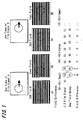
- FIGS. 1 and 2 show a processing for detecting a film signal.
- FIG. 1 shows a processing for detecting a 2:2 film signal to which a 2:2 pulldown processing (conversion to a PAL signal (576i) of 50 Hz) was implemented.
- the 2:2 film signal two fields are formed from the same frame by separating one frame of film into odd field and even field. Then, if a difference of each field between the signal and the one field delayed signal is taken, a difference between the same frames and a difference between the different frames are calculated alternately, so the difference changes alternately as 0, 1, 0, 1 ⁇ , in case of motion picture, and consequently that it is the 2:2 film signal is detected.
- FIG. 2 shows a processing for detecting a 3:2 film signal to which a 3:2 pulldown processing (conversion to a NTSC signal (480i) of 60 Hz) was implemented.
- a 3:2 pulldown processing conversion to a NTSC signal (480i) of 60 Hz
- three fields are formed from the frame of the same film and subsequently, two fields are formed from the frame of the same film, and then these states are continued alternately. Then, if a difference between the signal and the two field delayed signal is taken, a difference between the same fields is calculated at every five fields and the difference becomes 0, and consequently that it is the 3:2 film signal is detected.
- FIGS. 3A to 3C show a frame rate conversion processing by motion compensation as an example of the 2:2 film signal.
- the 2:2 film signal (PAL signal (576i) of 50 Hz) as shown in FIG. 3A is converted a progressive signal of 25 Hz by an IP conversion processing (2:2 pulldown reverse processing) by which the odd field and even field as shown in FIG. 3B are added, a motion vector is detected at interval of one field, as shown in FIG. 3C, and the intermediate field is interpolated by the motion compensation, thereby converting the frame rate from 25 Hz to 50 Hz.
- the motion of the image that is displayed becomes smooth by the frame rate conversion.
- An embodiment of the present invention is thus directed to recover degradation of the picture quality by the influence of noise in the video signal in a case in which there are implemented a progressive conversion processing and frame rate conversion processing to the signal converted to take a matching with the frame rate of the television video signal (called [telecine conversion] in either case in which an original image is an animation or computer graphic in the present description) by arranging an original image such as a 2:2 film signal, a 2:3 film signal or the like, on the basis of a predetermined sequence.
- a video signal processing apparatus includes a telecine conversion signal detecting unit, an IP converting unit, a noise level detecting unit and a control unit.
- the telecine conversion signal detecting unit detects whether or not an input video signal of interlaced system is a telecine converted video signal
- the IP converting unit converts the input video signal to a signal of progressive system, in accordance with a detected result of the telecine conversion signal detecting unit.
- the noise level detecting unit detects a noise level of the input video signal
- the control unit controls a detection sensitivity of the telecine conversion signal detecting unit to make difficult to detect that the input video signal is the telecine converted video signal in case of a higher noise level than a low noise level, on the basis of the detected result of the noise level detecting unit.
- the video signal processing apparatus implements a progressive conversion processing to an input video signal corresponding to a detected result of whether or not an input video signal is a telecine converted video signal, but a detection sensitivity of the telecine conversion signal detecting unit is controlled to make difficult to detect the input video signal being the telecine converted video signal, in a case in which a noise level of the input video signal is detected and the noise level is high.
- the progressive conversion processing for the telecine converted video signal becomes difficult to be carried out in the IP conversion unit, in a case in which a noise level of input video signal is high.
- the noise level of input video signal is high, the degradation of picture quality caused by switching the progressive conversion processing for telecine converted video signal and the progressive conversion processing for usual camera-signal frequently, as a cause of the malfunction of detection of the telecine converted video signal, is improved.
- a video signal processing apparatus includes a telecine conversion signal detecting unit, an IP converting unit, a frame rate converting unit, a noise level detecting unit and a control unit.
- the telecine conversion signal detecting unit detects whether or not an input video signal of interlaced system is a telecine converted video signal
- the IP converting unit converts the input video signal to a signal of progressive system in accordance with a detected result of the telecine conversion signal detecting unit.
- the frame rate converting unit converts a frame rate of the video signal converted to the signal of progressive system by the IP converting unit, in a case in which the video signal is detected to be a telecine converted video signal by said telecine conversion signal detecting unit, and the noise level detecting unit detects a noise level of the input video signal.
- the control unit turns a frame rate conversion processing of the frame rate converting unit on in a case in which the noise level is small, and turns the frame rate conversion processing of the frame rate converting unit off in a case in which the noise level is high, on the basis of the detected result of the noise level detecting unit.
- the video signal processing apparatus implements a progressive conversion processing corresponding to a detected result of whether an input video signal is a telecine converted video signal to an input video signal, and further a frame conversion processing is implemented to the telecine converted video signal after the progressive conversion processing, but the frame rate conversion processing is turned off, in a case in which a noise level of the input video signal is detected and the noise level is high.
- the noise level is high, the degradation of picture quality caused by switching the frame rate conversion processing on and off frequently, as a cause of the malfunction of detection of the telecine converted video signal, is improved, and also the image breakdown on a picture screen due to the malfunction of the motion vector detection is prevented.
- another video signal processing apparatus includes a telecine conversion signal detecting unit, an IP converting unit, a noise level detecting unit and a control unit.
- the telecine conversion signal detecting unit detects whether or not an input video signal of interlaced system is a telecine converted video signal and the IP converting unit converts the input video signal to a signal of progressive system in accordance with a detected result of the telecine conversion signal detecting unit.
- the noise level detecting unit detects a noise level of the input video signal
- the control unit turns a detection processing of the telecine conversion signal detecting unit off in a case in which the noise level is more than a predetermined level, on the basis of the detected result of the noise level detecting unit.
- the video signal processing apparatus implements a progressive conversion processing corresponding to a detected result of whether an input video signal is a telecine converted video signal to an input video signal, but a detection processing of the telecine conversion signal detecting unit is turned off, in a case in which a noise level of the input video signal is detected and the noise level is high.
- the progressive conversion processing for telecine converted video signal is not carried out in the IP conversion unit.
- the degradation of picture quality caused by switching the progressive conversion processing for telecine converted video signal and the progressive conversion processing for usual camera-signal frequently, as a cause of the malfunction of detection of the telecine converted video signal is improved.
- an image display apparatus has: a telecine conversion signal detecting unit which detects whether or not an input video signal of interlaced system is a telecine converted video signal; and an IP converting unit which converts the input video signal to a signal of progressive system in accordance with a detected result of the telecine conversion signal detecting unit, and displays the video signal converted to the signal of progressive system by said IP converting unit.
- the image display apparatus includes: a noise level detecting unit which detects a noise level of the input video signal; and a control unit which controls a detection sensitivity of the telecine conversion signal detecting unit to make difficult to detect it being the telecine converted video signal in case of a higher noise level than a low noise level, on the basis of the detected result of the noise level detecting unit.
- another image display apparatus has a telecine conversion signal detecting unit, an IP converting unit and a frame rate converting unit, and displays a frame rate converted video signal by the frame rate conversion unit.
- the telecine conversion signal detecting unit detects whether or not an input video signal of interlaced system is a telecine converted video signal and the IP converting unit converts said input video signal to a signal of progressive system in accordance with a detected result of the telecine conversion signal detecting unit.
- the frame rate converting unit converts a frame rate of the video signal converted to the signal of progressive system by the IP converting unit, in a case in which the video signal is detected to be a telecine converted video signal by said telecine conversion signal detecting unit.
- the image display apparatus includes: a noise level detecting unit which detects a noise level of the input video signal; and a control unit which turns a frame rate conversion processing of the frame rate converting unit on in a case in which the noise level is small, and turns the frame rate conversion processing of the frame rate converting unit off in a case in which the noise level is high, on the basis of the detected result of the noise level detecting unit.
- still another image display apparatus has: a telecine conversion signal detecting unit which detects whether or not an input video signal of interlaced system is a telecine converted video signal; and an IP converting unit which converts the input video signal to a signal of progressive system in accordance with a detected result of the telecine conversion signal detecting unit, and displays the video signal converted to the signal of progressive system by said IP converting unit.
- the image display apparatus includes: a noise level detecting unit which detects a noise level of said input video signal; and a control unit which turns a detection processing of said telecine conversion signal detecting unit off in a case in which the noise level is more than a predetermined level, on the basis of the detected result of the noise level detecting unit.
- These image display apparatuses are to include the aforementioned video signal processing apparatus according to an embodiment of the present invention respectively and to implement the progressive conversion processing (or the progressive conversion processing and frame rate conversion processing) to the telecine converted processing and to display it.
- the progressive conversion processing or the progressive conversion processing and frame rate conversion processing
- the noise level of input video signal is high
- the degradation of picture quality caused by switching the frame rate conversion processing for telecine converted video signal and the frame rate conversion processing for usual camera-signal frequently, as a cause of the malfunction of detection of the telecine converted video signal is improved.
- the degradation of picture quality caused by switching the frame rate conversion processing on and off frequently, as a cause of the malfunction of detection of the telecine converted video signal is improved, and also the image breakdown on a picture screen due to the malfunction of the motion vector detection is prevented.
- the video signal processing apparatus implements a progressive conversion processing corresponding to a detected result of whether an input video signal is a telecine converted video signal to an input video signal
- the progressive conversion processing corresponding to a detected result of whether an input video signal is a telecine converted video signal to an input video signal is implemented and further the frame rate conversion processing is implemented to the telecine converted video signal after the progressive conversion processing
- the degradation of picture quality caused by switching the frame rate conversion processing on and off frequently, as a cause of the malfunction of detection of the telecine converted video signal may be improved in a case in which the noise level of the input video signal is high.
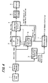
- FIG. 4 is a block diagram showing a configuration of main portion of the television receiving apparatus to which an embodiment of the present invention is applied.
- a RF signal that is transmitted to a frontend 1 from an antenna (not shown)
- it is selected at the frontend 1 and is demodulated, and a video signal in an interlaced system (interlace format) to which a Y/C separation processing and chroma decoding processing are implemented by a chroma decoder (NTSC signal (480i), PAL signal (576i) or HDTV signal (1080i)) is transmitted to a noise level detecting circuit 3, an IP converting circuit 4 and a film signal detecting circuit 5, respectively.
- NTSC signal 480i
- PAL signal PAL signal
- HDTV signal 1080i
- the film signal detecting circuit 5 is a circuit that detects whether or not an input video signal is a 2:2 film signal or a 2:3 film signal by the method shown in FIGS. 1 and 2.
- a signal showing a detected result (a signal showing which one of a 2:2 film signal, 2:3 film signal and usual camera-signal the input video signal is) is transmitted to the IP converting circuit 4 and frame rate conversion circuit 6 from the film signal detecting circuit 5.
- the IP converting circuit 4 is a circuit that implements an IP conversion processing by which the input video signal of interlaced system is converted to a signal of progressive system (called progressive-conversion, hereinafter), and the IP conversion processing for film signal (for example, such pulldown reverse processing shown in FIG. 6, for the 2:2 film signal) is implemented if the detected result of the film signal detecting circuit 5 is the 2:2 film signal or 3:2 film signal, on the other hand, the IP conversion processing for usual camera-signal is implemented if the detected result of the film signal detecting circuit 5 is the usual camera-signal.
- the video, signal (NTSC signal (480i), PAL signal (576i) or HDTV signal (1080i)) progressive-converted at the IP converting circuit 4 is transmitted to the frame rate conversion circuit 6.
- the frame rate conversion circuit 6 is a circuit that implements the frame conversion processing from 25 Hz to 50 Hz (for example, such processing shown in FIG. 6, for the 2:2 film signal) by implementing a motion compensation of interpolation frame to the progressive converted video signal by the IP converting circuit 4, in a case in which the detected result of the film signal detecting circuit 5 is the 2:2 film signal or the 3:2 film signal.
- the frame rate conversion is not implemented in the frame rate converting circuit 6 if the detected result of the film signal detecting circuit 5 is the usual camera-signal.
- the video signal outputted from the frame rate converting circuit 6 is transmitted to a display driving circuit 8 and a display (for example, LCD) 9 is driven by the display driving circuit 8 and an image is displayed.
- a display for example, LCD
- the noise level detecting circuit 3 is a circuit that detects a noise level of the input video signal.
- the noise level detecting circuit 3 detects noise information (AC component) on a pedestal portion of one horizontal line in equalization pulse interval inside a vertical blanking interval of the input video signal, for example, and a voltage obtained from the AC component that is filtered by a filter with about 160 Hz cutoff frequency is detected as a noise value YNLV. Then, noise levels (SNLVO to SNLV7) that change to eight levels by this noise value YNLV is detected (NLVO indicates the noise level in the smallest level, Whereas NLV7 indicates the noise level in the largest level).
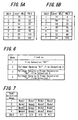
- FIGS. 5A and 5B are a diagram that illustrates the detected results of the noise levels (SNLVO to SNLV7), and FIG. 5A is the detected results at the time of increasing the noise level by decreasing the field strength of RF signal (level_dBu) from the receiving antenna. Conversely, FIG. 5B is the detected results at the time of decreasing the noise level by increasing the field strength of RF signal (level_dBu) from the receiving antenna.
- the noise level SNLV is changed to 1 (before, the noise level SNLV is 0) if the noise value YNLV becomes equal to or more than 10 (field strength (level_dBu) is equal to or less than 70 dBu) at the time of decreasing the field strength (level_dBu).
- the noise level SNLV is changed to 2 if the noise value YNLV becomes equal to or more than 20 (field strength (level_dBu) is equal to or less than 65 dBu).
- the noise level SNLV is changed to 3 if the noise value YNLV becomes equal to or more than 30 (field strength (level_dBu) is equal to or less than 62 dBu).
- the noise level SNLV is changed to 4 if the noise value YNLV becomes equal to or more than 50 (field strength (level_dBu) is equal to or less than 58 dBu).
- the noise level SNLV is changed to 5 if the noise value YNLV becomes equal to or more than 70 (field strength (level_dBu) is equal to or less than 55 dBu).
- the noise level SNLV is changed to 6 if the noise value YNLV becomes equal to or more than 100 (field strength (level_dBu) is equal to or less than 50 dBu).
- the noise level SNLV is changed to 7 if the noise value YNLV becomes equal to or more than 150 (field strength (level_dBu) is equal to or less than 35 dBu).
- the noise level SNLV is not changed to 6 from 7 even if the noise value YNLV becomes less than 150 (field strength (level_dBu) is more than 35 dBu), and is changed to 6 from 7 if the noise value YNLV begins to become less than 120 (field strength (level_dBu) is equal to or more than 44 dBu) being smaller than 150, at the time of increasing the field strength (level_dBu), as shown in FIG. 5B.
- the noise level SNLV is not changed to 5 from 6 even if the noise value YNLV becomes less than 100 (field strength (level_dBu) is more than 50 dBu), and is changed to 5 from 6 if the noise value YNLV begins to become less than 100 (field strength (level_dBu) is equal to or more than 53 dBu) being smaller than 100.
- the noise values YNLV that change the noise level SNLV to 4, 3, 2, 1 and 0 are set up lower than ones at the time of decreasing the field strength (level_dBu).
- the noise level detected by the noise level detecting circuit 3 has a hysteresis characteristic such that the increase of the field strength of RF signal from the antenna (decrease of the noise value) is more difficult to recover to suitable level than the decrease of the field strength of RF signal (increase of the noise value).
- a detected result of the noise level is transmitted to a microcomputer 7 from the noise level detecting circuit 3.
- the noise level detecting circuit 3 is provided other than the chroma decoder 2, but the noise level detecting circuit 3 may be included in the chroma decoder 2.
- FIG. 6 shows an example of combination of selectable modes by the remote control.
- the remote controller is possible to select four kinds of modes from mode 1 to mode 4.
- the mode 1 is a mode that turns the detection processing of the film signal off.
- the detected result that indicates that the input video signal is the camera-signal is transmitted to the IP converting circuit 4 and frame rate converting circuit 6 from the film signal detecting circuit 5. Therefore, the IP conversion processing for film signal (pulldown reverse processing) is not implemented in the IP converting circuit 4 and the IP conversion processing for usual camera-signal is typically implemented and the frame rate conversion processing is not implemented in the frame rate converting circuit 6.
- the mode 2 is a mode which sets up parameters that control a detection sensitivity of the film signal detecting circuit 5 to "film detection 2" and which turns the IP conversion processing for film signal (pulldown reverse processing) of the IP converting circuit 4 on and which turns the frame rate conversion processing of the frame rate converting circuit 6 off.
- the mode 2 if the film signal is detected by the film signal detecting circuit 5, the IP conversion processing for film signal is implemented in the IP converting circuit 4, but the frame rate conversion processing is not implemented in the frame rate conversion circuit 6.
- Frm detection 1 it is a parameter by which the film signal detection becomes easy and by which the film signal detection becomes difficult after detecting the film signal once (detection sensitivity is increased). The following examples are cited for embodiments of such parameter:
- “Film detection 2” it is a reverse for “Film detection 2", and it is a parameter by which the film signal detection becomes easy and by which the detection of being not the film signal becomes easy after detecting the film signal once (detection sensitivity is decreased).
- the mode 3 is a mode by which the parameter that controls the detection sensitivity of the film signal detecting circuit 5 is set up to "film detection 2" and by which the IP conversion processing for film signal of the IP converting circuit 4 (pulldown reverse processing) is turned on and by which the frame rate conversion processing of the frame rate converting circuit 6 is also turned on.
- the mode 3 if the film signal is detected in the film signal detecting circuit 5, the IP conversion processing for film signal is implemented in the IP converting circuit 4 and also the frame rate conversion processing is implemented in the frame rate converting circuit 6.
- the detection sensitivity of the film signal detecting circuit 5 becomes weak, it becomes difficult to implement the IP conversion processing for film signal in the IP converting circuit 4 and it becomes difficult to implement the frame rate conversion processing in the frame rate converting circuit 6; too.
- the mode 4 is a mode by which the parameter that controls the detection sensitivity of the film signal detecting circuit 5 is set up to "film detection 1" and by which the IP conversion processing for film signal of the IP converting circuit 4 (pulldown reverse processing) is turned on and by which the frame rate conversion processing of the frame rate converting circuit 6 is also turned on.
- the mode 4 if the film signal is detected in the film signal detecting circuit 5, the IP conversion processing for film signal is implemented in the IP converting circuit 4 and also the frame rate conversion processing is implemented in the frame rate converting circuit 6. Then, because the detection sensitivity of the film signal detecting circuit 5 becomes strong, it becomes easy to implement the IP conversion processing for film signal in the IP converting circuit 4 and it becomes easy to implement the frame rate conversion processing in the frame rate converting circuit 6, too.
- the signal that indicates the selected result of the modes 1 to 4 is supplied to the microcomputer 7 from the remote controller through an infrared receiving sensor unit or the like that is not shown.
- the microcomputer 7 changes the mode dynamically and controls the IP converting circuit 4, film signal detecting circuit 5 and frame rate converting circuit 6, as shown in FIG. 7, on the basis of the selected result of the modes 1 to 4 by the user and the selected result of the noise levels SNLV0 to SNLV7 by the noise level detecting circuit 3. Specifically, in a case in which the noise level is SNLV0 or SNLV1 (level where the field strength of RF signal is strong and the noise level is small), the control of the IP converting circuit 4, the control of the detection sensitivity of the film signal detecting circuit 5 (the change of the parameter or the detection processing turning off) and the ON/OFF control of the frame rate conversion processing of the frame rate converting circuit 6 are implemented in accordance with the modes 1 to 4 selected by the user.
- the control of the IP converting circuit 4 the control of the detection sensitivity of the film signal detecting circuit 5 and the ON/OFF control of the frame rate conversion processing of the frame rate converting circuit 6 are implemented in accordance with the mode in a case in which the user selects the modes 1 or 2.
- the control of the IP converting circuit 4, the control of the detection sensitivity of the film signal detecting circuit 5 and the ON/OFF control of the frame rate conversion processing of the frame rate converting circuit 6 are implemented forcibly by the mode 2, in a case in which the user selects the modes 3 or 4. Therefore, in this case, the frame rate conversion processing is not implemented in the frame rate converting circuit 6 and also the detection sensitivity of the film signal becomes weak, so it becomes difficult to implement the IP conversion processing for film signal in the IP converting circuit 4, too.
- the control of the IP converting circuit 4 the control of the detection sensitivity of the film signal detecting circuit 5 and the ON/OFF control of the frame rate conversion processing of the frame rate converting circuit 6 are implemented forcibly by the mode 1, in a case in which the user selects any one of the modes 1 to 4. Therefore, the IP conversion processing for film signal is not implemented in the IP converting circuit 4 and the IP conversion processing for camera-signal is typically implemented and the frame rate conversion processing is not implemented in the frame rate conversion circuit 6.
- the detection sensitivity of the film signal detecting circuit 5 is controlled to make difficult to detect that the input signal is the telecine converted video signal in case of a higher (bigger) noise level than a low (small) noise level, on the basis of the detected result of the noise level detecting circuit 5.
- the microcomputer 7 controls to turn on the frame rate conversion processing of the frame rate conversion circuit 6 if the noise level is lower than a predetermined value, and to turn off the frame rate conversion processing of the frame rate conversion circuit 6 if the noise level is equal to or higher than the predetermined value based on the detected result of the noise level detecting circuit 3 in each mode.
- the noise levels SNLV0 to SNLV7 have a hysteresis characteristic such that the increase of the field strength of RF signal (decrease of the noise value) is more difficult to recover to suitable level than the decrease of the field strength of RF signal (increase of the noise value). Therefore, the mode change of a case in which the control of the microcomputer 7 moves to the mode of right side from the mode of left side in FIG. 7 by decreasing the field strength of RF signal becomes easier than a case in which the control of the microcomputer 7 returns to the mode of left side from the mode of right side in FIG. 7 by increasing the field strength of RF signal after that. Thus, after the field strength becomes weak once, the mode (mode 1 or mode 2) to improve the degradation of the picture quality is maintained until the field strength becomes strong enough.
- the video signal to which the detection processing, progressive conversion processing and frame rate conversion processing of the embodiment of the present invention are applied may be any kinds of video signals that are converted (telecine-converted) to make matching with the frame rate of the television signal by arranging the original image such as the cinema, animation or computer graphic, on the basis of the predetermined sequence.
- the embodiment of the present invention is applied to the television receiving apparatus, but the image display apparatus according to an embodiment of the present invention may be applied to a personal computer including a receiving function of the television broadcast, other than the television receiving apparatus.
- the video processing apparatus according to an embodiment of the present invention may be included into a recording/reproducing apparatus that receives the television broadcast and records and/or reproduces it (DVD recorder or HDD recorder or the like).
Landscapes
- Engineering & Computer Science (AREA)
- Multimedia (AREA)
- Signal Processing (AREA)
- Computer Graphics (AREA)
- Television Systems (AREA)
Applications Claiming Priority (1)
| Application Number | Priority Date | Filing Date | Title |
|---|---|---|---|
| JP2006141835A JP4863767B2 (ja) | 2006-05-22 | 2006-05-22 | 映像信号処理装置及び画像表示装置 |
Publications (2)
| Publication Number | Publication Date |
|---|---|
| EP1860876A2 true EP1860876A2 (fr) | 2007-11-28 |
| EP1860876A3 EP1860876A3 (fr) | 2012-07-11 |
Family
ID=38457861
Family Applications (1)
| Application Number | Title | Priority Date | Filing Date |
|---|---|---|---|
| EP07252091A Withdrawn EP1860876A3 (fr) | 2006-05-22 | 2007-05-22 | Appareil de traitement de signal vidéo et appareil d'affichage d'images |
Country Status (4)
| Country | Link |
|---|---|
| US (1) | US8754937B2 (fr) |
| EP (1) | EP1860876A3 (fr) |
| JP (1) | JP4863767B2 (fr) |
| CN (1) | CN101079958B (fr) |
Cited By (2)
| Publication number | Priority date | Publication date | Assignee | Title |
|---|---|---|---|---|
| CN102760463A (zh) * | 2011-04-27 | 2012-10-31 | 佛山市南海平板显示技术中心 | 一种用于视频处理的memc装置 |
| CN102761725A (zh) * | 2011-04-27 | 2012-10-31 | 佛山市南海平板显示技术中心 | 一种液晶显示器 |
Families Citing this family (17)
| Publication number | Priority date | Publication date | Assignee | Title |
|---|---|---|---|---|
| JP4465553B2 (ja) * | 2005-05-30 | 2010-05-19 | 有限会社ティーシーラボ | 一般的なビデオカメラ回路を利用したテレシネ装置 |
| JP4863767B2 (ja) * | 2006-05-22 | 2012-01-25 | ソニー株式会社 | 映像信号処理装置及び画像表示装置 |
| CN101543065B (zh) * | 2007-02-20 | 2012-03-14 | 索尼株式会社 | 图像显示装置、视频信号处理器以及视频信号处理方法 |
| CN101971622A (zh) * | 2008-03-24 | 2011-02-09 | 松下电器产业株式会社 | 影像处理装置 |
| US8462264B2 (en) * | 2008-04-23 | 2013-06-11 | Panasonic Corporation | Video scan converter for performing interlaced to progressive scan conversion |
| US20110001873A1 (en) * | 2008-08-06 | 2011-01-06 | Daniel Doswald | Frame rate converter for input frames with video and film content |
| WO2010038197A1 (fr) * | 2008-09-30 | 2010-04-08 | Nxp B.V. | Profil pour une conversion de vitesse de trame |
| JP2012044233A (ja) * | 2008-12-12 | 2012-03-01 | Panasonic Corp | 再生装置 |
| DE102009013673A1 (de) * | 2009-03-09 | 2010-09-16 | Eppendorf Ag | Zellkulturschale |
| JP4575503B2 (ja) | 2009-03-12 | 2010-11-04 | 株式会社東芝 | 放送受信装置および放送受信方法 |
| JP2010286587A (ja) * | 2009-06-10 | 2010-12-24 | Sony Corp | 画像表示装置、画像表示観察システム、画像表示方法、及びプログラム |
| WO2011071469A1 (fr) * | 2009-12-09 | 2011-06-16 | Thomson Licensing | Contenu progressif par décroissance de luminophore |
| EP2628294A1 (fr) * | 2010-10-15 | 2013-08-21 | Thomson Licensing | Procédé et système permettant de produire une archive vidéo sur un film |
| TW201228403A (en) * | 2010-12-28 | 2012-07-01 | Acer Inc | Video display device, multi-media vedio streamoing device, and method thereof |
| US9332216B2 (en) * | 2014-03-12 | 2016-05-03 | Sony Computer Entertainment America, LLC | Video frame rate compensation through adjustment of vertical blanking |
| CN108810648A (zh) * | 2018-06-29 | 2018-11-13 | 青岛海信电器股份有限公司 | 一种进行图像处理的方法及终端 |
| CN111541940B (zh) * | 2020-04-30 | 2022-04-08 | 深圳创维-Rgb电子有限公司 | 显示设备的运动补偿方法、装置、电视机及存储介质 |
Citations (4)
| Publication number | Priority date | Publication date | Assignee | Title |
|---|---|---|---|---|
| EP0720366A2 (fr) | 1994-12-30 | 1996-07-03 | Thomson Consumer Electronics, Inc. | Méthode et appareil pour l'identification de trames vidéo produites par des sources de films utilisant des séquences d'entraînements intermittents 2-2 et 3-2 |
| US5892550A (en) | 1995-06-08 | 1999-04-06 | Matsushita Electric Industrial Co., Ltd. | Television signal conversion system and image encoding and decoding system |
| EP1503582A1 (fr) | 2003-07-31 | 2005-02-02 | Pioneer Corporation | Appareil pour la conversion d'un signal video |
| EP1592250A1 (fr) | 2004-04-30 | 2005-11-02 | Matsushita Electric Industrial Co., Ltd. | Detection de mode cinéma dans des séquences vidéo |
Family Cites Families (32)
| Publication number | Priority date | Publication date | Assignee | Title |
|---|---|---|---|---|
| EP0004728B1 (fr) * | 1978-04-03 | 1982-04-28 | British Broadcasting Corporation | Réduction du bruit dans des signaux électriques |
| WO1983003513A1 (fr) * | 1982-03-30 | 1983-10-13 | Childs, Ian | Ameliorations aux appareils de telecinema |
| US4581641A (en) * | 1984-10-18 | 1986-04-08 | Zenith Electronics Corporation | Video noise detector |
| US4641188A (en) * | 1985-07-31 | 1987-02-03 | Rca Corporation | Progressive scan display system employing line and frame memories |
| US5049984A (en) * | 1989-09-12 | 1991-09-17 | Eastman Kodak Company | Motion picture telecine balanced for negative scanning |
| JP3094339B2 (ja) * | 1990-07-20 | 2000-10-03 | 松下電器産業株式会社 | 輝度信号ノイズ抑圧装置 |
| US6002451A (en) * | 1995-01-25 | 1999-12-14 | Mitsubishi Denki Kabushiki Kaisha | Automatic tuning apparatus for a video tape recorder |
| JP3849299B2 (ja) * | 1998-05-29 | 2006-11-22 | 松下電器産業株式会社 | テレビジョン受像機 |
| JP3863294B2 (ja) * | 1998-07-02 | 2006-12-27 | 株式会社日立製作所 | ノイズ低減信号処理回路および映像表示装置 |
| US6297848B1 (en) * | 1998-11-25 | 2001-10-02 | Sharp Laboratories Of America, Inc. | Low-delay conversion of 3:2 pulldown video to progressive format with field averaging |
| US6408024B1 (en) * | 1999-05-12 | 2002-06-18 | Matsushita Electric Industrial Co., Ltd. | Telecine video signal detecting device |
| US6864913B2 (en) * | 1999-12-23 | 2005-03-08 | Harry L. Tarnoff | Method and apparatus for a reconfigurable digital processor for film conversion |
| US7203238B2 (en) * | 2000-12-11 | 2007-04-10 | Sony Corporation | 3:2 Pull-down detection |
| JP3692963B2 (ja) * | 2001-04-27 | 2005-09-07 | ソニー株式会社 | 映像源判別方法及び装置及び映像信号処理装置 |
| JP4538174B2 (ja) * | 2001-08-31 | 2010-09-08 | パイオニア株式会社 | 映像信号のテレシネ変換方式検出装置 |
| GB0121737D0 (en) * | 2001-09-07 | 2001-10-31 | Pandora Int Ltd | Visual programming language |
| JP2004034333A (ja) | 2002-06-28 | 2004-02-05 | Daiwa Seiko Inc | 装飾部を有する部材及びその製造方法 |
| KR100518580B1 (ko) * | 2003-06-10 | 2005-10-04 | 삼성전자주식회사 | 인버스 텔레시네 변환장치 및 변환방법 |
| US7420618B2 (en) * | 2003-12-23 | 2008-09-02 | Genesis Microchip Inc. | Single chip multi-function display controller and method of use thereof |
| JP3760943B2 (ja) * | 2004-01-20 | 2006-03-29 | コニカミノルタフォトイメージング株式会社 | 撮像装置および動画のノイズ処理方法 |
| US7529426B2 (en) * | 2004-01-30 | 2009-05-05 | Broadcom Corporation | Correlation function for signal detection, match filters, and 3:2 pulldown detection |
| JP2005286413A (ja) * | 2004-03-26 | 2005-10-13 | Toshiba Corp | ノイズ低減装置及びテレビジョン受像機 |
| US7630014B2 (en) * | 2004-04-30 | 2009-12-08 | Brett James Pardikes | Lighting apparatus for attachment to a camera's tripod mount and method of use |
| EP1631068A3 (fr) * | 2004-08-26 | 2008-09-03 | Samsung Electronics Co., Ltd. | Dispositif et procédé de conversion d' image entrelacée en image progressive |
| KR100577684B1 (ko) * | 2004-10-08 | 2006-05-10 | 삼성전자주식회사 | 저더-맵을 이용한 영상 처리 장치 및 방법 |
| JP3916637B2 (ja) * | 2005-03-08 | 2007-05-16 | 三菱電機株式会社 | 映像信号処理装置、映像信号処理方法、及び映像信号表示装置 |
| JP2006279563A (ja) * | 2005-03-29 | 2006-10-12 | Pioneer Electronic Corp | 画質調整装置、画質調整方法およびディスプレイ装置 |
| US7555715B2 (en) * | 2005-10-25 | 2009-06-30 | Sonic Solutions | Methods and systems for use in maintaining media data quality upon conversion to a different data format |
| US7667776B2 (en) * | 2006-02-06 | 2010-02-23 | Vixs Systems, Inc. | Video display device, video encoder, noise level estimation module and methods for use therewith |
| JP4863767B2 (ja) * | 2006-05-22 | 2012-01-25 | ソニー株式会社 | 映像信号処理装置及び画像表示装置 |
| EP1865730A3 (fr) * | 2006-06-06 | 2010-01-20 | Sony Corporation | Procédé de traitement de signal vidéo, programme de procédé de traitement de signal vidéo, support d'enregistrement comportant un programme associé enregistré d'un procédé de traitement de signal vidéo, et appareil de traitement de signal vidéo |
| CN101543065B (zh) * | 2007-02-20 | 2012-03-14 | 索尼株式会社 | 图像显示装置、视频信号处理器以及视频信号处理方法 |
-
2006
- 2006-05-22 JP JP2006141835A patent/JP4863767B2/ja not_active Expired - Fee Related
-
2007
- 2007-05-21 US US11/751,532 patent/US8754937B2/en not_active Expired - Fee Related
- 2007-05-22 CN CN2007101079769A patent/CN101079958B/zh not_active Expired - Fee Related
- 2007-05-22 EP EP07252091A patent/EP1860876A3/fr not_active Withdrawn
Patent Citations (4)
| Publication number | Priority date | Publication date | Assignee | Title |
|---|---|---|---|---|
| EP0720366A2 (fr) | 1994-12-30 | 1996-07-03 | Thomson Consumer Electronics, Inc. | Méthode et appareil pour l'identification de trames vidéo produites par des sources de films utilisant des séquences d'entraînements intermittents 2-2 et 3-2 |
| US5892550A (en) | 1995-06-08 | 1999-04-06 | Matsushita Electric Industrial Co., Ltd. | Television signal conversion system and image encoding and decoding system |
| EP1503582A1 (fr) | 2003-07-31 | 2005-02-02 | Pioneer Corporation | Appareil pour la conversion d'un signal video |
| EP1592250A1 (fr) | 2004-04-30 | 2005-11-02 | Matsushita Electric Industrial Co., Ltd. | Detection de mode cinéma dans des séquences vidéo |
Cited By (3)
| Publication number | Priority date | Publication date | Assignee | Title |
|---|---|---|---|---|
| CN102760463A (zh) * | 2011-04-27 | 2012-10-31 | 佛山市南海平板显示技术中心 | 一种用于视频处理的memc装置 |
| CN102761725A (zh) * | 2011-04-27 | 2012-10-31 | 佛山市南海平板显示技术中心 | 一种液晶显示器 |
| CN102761725B (zh) * | 2011-04-27 | 2016-02-17 | 佛山市南海平板显示技术中心 | 一种液晶显示器 |
Also Published As
| Publication number | Publication date |
|---|---|
| US8754937B2 (en) | 2014-06-17 |
| US20070296811A1 (en) | 2007-12-27 |
| EP1860876A3 (fr) | 2012-07-11 |
| CN101079958A (zh) | 2007-11-28 |
| JP4863767B2 (ja) | 2012-01-25 |
| CN101079958B (zh) | 2011-12-07 |
| JP2007312317A (ja) | 2007-11-29 |
Similar Documents
| Publication | Publication Date | Title |
|---|---|---|
| US8754937B2 (en) | Video signal processing apparatus and image display apparatus | |
| US6414719B1 (en) | Motion adaptive median filter for interlace to progressive scan conversion | |
| US7193655B2 (en) | Process and device for de-interlacing by pixel analysis | |
| US8115867B2 (en) | Image processing device | |
| JP2007259314A (ja) | 字幕検出装置及び字幕検出方法ならびにプルダウン信号検出装置 | |
| JP2005175671A (ja) | ノイズ低減回路及び方法 | |
| EP1503582A1 (fr) | Appareil pour la conversion d'un signal video | |
| GB2422978A (en) | Image quality correction based on detected frame encoding and bit rate information | |
| KR100472436B1 (ko) | 디지털 텔레비전에서의 적응적 외부 입력 비디오 신호의처리장치 | |
| US20060268175A1 (en) | Display apparatus and control method thereof | |
| US8836859B2 (en) | Image processing apparatus, image processing method and image display apparatus | |
| CN101521785A (zh) | 视频信号处理设备和方法 | |
| JP4055109B2 (ja) | インターレース映像信号の動き検出装置及びこれを用いた順次走査変換装置 | |
| JP5172999B2 (ja) | 映像信号処理装置及び画像表示装置 | |
| US5227866A (en) | Television receiver for extended definition video signal detects number of scan lines and controls signal processors | |
| JP2007274411A (ja) | プルダウン信号検出装置およびプルダウン信号検出方法並びに順次走査変換装置および順次走査変換方法 | |
| US8164687B2 (en) | Color difference signal IP conversion method | |
| JP4236233B2 (ja) | 映像信号処理回路 | |
| CN102308576A (zh) | 影像处理装置 | |
| JP4936857B2 (ja) | プルダウン信号検出装置、プルダウン信号検出方法及び順次走査変換装置 | |
| JP5265048B2 (ja) | 映像信号処理装置及び画像表示装置 | |
| EP0772351B1 (fr) | Détection de mouvement pour signaux vidéo entrelacés | |
| WO2009081627A1 (fr) | Appareil et procédé de traitement d'interpolation, et appareil d'affichage d'image | |
| JP2008009182A (ja) | 液晶表示装置 | |
| JP2007074439A (ja) | 映像処理装置 |
Legal Events
| Date | Code | Title | Description |
|---|---|---|---|
| PUAI | Public reference made under article 153(3) epc to a published international application that has entered the european phase |
Free format text: ORIGINAL CODE: 0009012 |
|
| AK | Designated contracting states |
Kind code of ref document: A2 Designated state(s): AT BE BG CH CY CZ DE DK EE ES FI FR GB GR HU IE IS IT LI LT LU LV MC MT NL PL PT RO SE SI SK TR |
|
| AX | Request for extension of the european patent |
Extension state: AL BA HR MK YU |
|
| RIN1 | Information on inventor provided before grant (corrected) |
Inventor name: NAGATSU, YOSHIHIDE Inventor name: MIYAZAKI, SHINICHIRO |
|
| PUAL | Search report despatched |
Free format text: ORIGINAL CODE: 0009013 |
|
| AK | Designated contracting states |
Kind code of ref document: A3 Designated state(s): AT BE BG CH CY CZ DE DK EE ES FI FR GB GR HU IE IS IT LI LT LU LV MC MT NL PL PT RO SE SI SK TR |
|
| AX | Request for extension of the european patent |
Extension state: AL BA HR MK RS |
|
| RIC1 | Information provided on ipc code assigned before grant |
Ipc: H04N 7/01 20060101AFI20120601BHEP |
|
| 17P | Request for examination filed |
Effective date: 20121227 |
|
| AKX | Designation fees paid |
Designated state(s): DE FR GB |
|
| STAA | Information on the status of an ep patent application or granted ep patent |
Free format text: STATUS: THE APPLICATION HAS BEEN WITHDRAWN |
|
| 18W | Application withdrawn |
Effective date: 20150121 |