EP1860965B1 - Casque de protection pour faire du sport et pour travailler - Google Patents
Casque de protection pour faire du sport et pour travailler Download PDFInfo
- Publication number
- EP1860965B1 EP1860965B1 EP06707226A EP06707226A EP1860965B1 EP 1860965 B1 EP1860965 B1 EP 1860965B1 EP 06707226 A EP06707226 A EP 06707226A EP 06707226 A EP06707226 A EP 06707226A EP 1860965 B1 EP1860965 B1 EP 1860965B1
- Authority
- EP
- European Patent Office
- Prior art keywords
- helmet
- cap
- front cap
- rear cap
- rack
- Prior art date
- Legal status (The legal status is an assumption and is not a legal conclusion. Google has not performed a legal analysis and makes no representation as to the accuracy of the status listed.)
- Expired - Lifetime
Links
Images






Classifications
-
- A—HUMAN NECESSITIES
- A42—HEADWEAR
- A42B—HATS; HEAD COVERINGS
- A42B3/00—Helmets; Helmet covers ; Other protective head coverings
- A42B3/32—Collapsible helmets; Helmets made of separable parts ; Helmets with movable parts, e.g. adjustable
- A42B3/324—Adjustable helmets
Definitions
- the present invention relates generally to a protective helmet and, more particularly, to a protective helmet for sports and/or work use.
- a helmet generally comprises: a rigid outer shell to prevent direct contact between the user's head and rigid objects and to distribute the impact force produced thereby over a large surface; and an inner shell of deformable material, typically expanded polystyrene, to absorb said impact force.
- each helmet model is available commercially in numerous different sizes.
- the helmet size is a very important parameter in its choice, for reasons both of comfort and of safety.
- the helmet must be able to surround the user's head so that this latter is unable to move within its interior and, especially, so that the helmet is unable to accidentally shift following an impact.
- the user is able to choose the helmet only within a discrete range of dimensions, which do not always exactly match user requirements.
- Helmets with a size adjustment system also exist, composed of an adjustable ring fixed to the helmet interior to surround the head.
- this known system partially aids size adjustment, the head withdraws, even by a considerable extent, from the inner surface of the protective shell during adjustment, so that when an impact occurs the head itself impacts against this inner surface.
- US 3,204,251 discloses a safety helmet comprising two complementary, cooperating forward and rearward head-encompassing sections of relatively stiff material, said sections having side walls, said side walls having slots therein, one such section being received within the other section to permit of their relative displacement in a vertical plane passing through the longitudinal axis of the helmet thereby to modify the effective longitudinal cross-section of the helmet better to fit the helmet to the wearer's head, and means, including fastening means passing through the slots in the side walls of said sections, for releasably locking said sections in selected relative positions.
- An object of the present invention is to overcome the stated drawbacks, by providing a helmet which adapts to the user's head while at the same time being able to accommodate, by a single model, a plurality of different sizes, so advantageously reducing the firm's production costs.
- a further object of the invention is to achieve the aforesaid objects within the framework of a simple, rational and low-cost solution.
- a protective helmet particularly for sports use, comprising a rigid outer shell which itself comprises a front cap having a concavity able to cover at least the upper part of the cranium, and a rear cap having a concavity able to cover the rear part of the cranium.
- said front and rear caps are mutually movable, the rear cap being connected to the front cap in such a manner as to rotate relative to this latter about an axis transverse to the vertical plane of symmetry of the cranium, between a raised position and a lowered position.
- the perimeter of the lower edge of the helmet can be infinitely modified between a maximum value and a minimum value, so reducing or increasing the helmet entry dimension.
- the helmet also comprises an inner shell for absorbing impacts, and adjustment means for tightening/loosening said inner shell, to advantageously vary the inner width or entry of the helmet. If impact occurs, the perfect fit between the head and the protective shell reduces the impact effect and increases user safety.
- the helmet 1 shown in the accompanying drawings is a helmet particularly designed for winter sports, and is in the form of a jet or semi-integral helmet, which leaves the user's forehead and face uncovered; however the invention can evidently relate to any type of helmet, independently of the use for which it is intended.
- the helmet 1 comprises a rigid outer shell of plastic material, comprising two separate caps, namely a front cap 2 with its concavity suitable for covering the upper part of the cranium, and a rear cap 3 for covering the rear part of the cranium.
- the front cap 2 covers the frontal and parietal bones of the cranium and is provided with two opposing lateral extensions 20 which partly cover the temporal bones of the cranium, the ears and the lateral parts of the face.
- the rear cup 3 covers the occipital bones of the cranium as far as the nape of the neck, and partly the temporal bones.
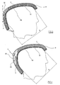
- said front cap 2 and rear cap 3 are mutually movable, and are connected together such that the rear cap 3 can rotate relative to the front cap 2 about an axis A transverse to the plane of vertical symmetry of the cranium, between a raised position and a lowered position (see Figures 1 , 5 and 3 , 6 respectively).
- the entry dimension of the helmet 1, indicated by B in the figures is a maximum; whereas when the rear cap 3 is in its lowered position, said entry dimension B reaches its minimum value.
- the entry dimension B of the helmet 1 can be advantageously adjusted continuously, and hence adapted to the user's cranium.
- the invention enables the entry dimension B to be varied by about 16 mm, it enables about one half of the commercially available helmet sizes to be covered by a single model.
- the rotation axis A must preferably be positioned within that region of the helmet 1 covering the side part of the cranium above the ear, i.e. substantially within that region covering that part of the cranium at the boundary between the parietal and temporal bones.
- the front cap 2 is provided with two prolongations 21, each projecting from the rear edge of a respective extension 20 and arranged to slide in contact with the inner surface of the rear cap 3.
- the rear cap 3 is provided with a prolongation 30 projecting from its upper edge, to slide in contact with the inner surface of the front cap 2.
- the outer shell of the helmet 1 advantageously preserves its own structural continuity, whatever the position assumed by the rear cap 3 relative to the front cap 2, to ensure better protection of the user's cranium.
- the upper prolongation 30 of the rear cap 3 is shaped to present two opposing sidepieces 31 extending towards the front of the helmet 1 and situated in the user's temple regions.
- the front cap 2 and rear cap 3 are connected together by hinges, the helmet 1 comprising at least one locking device able to provide a locking action, disengagable by manual control. which prevents mutual rotation between the front cap 2 and the rear cap 3.
- the rear cap 3 is hinged to the front cap 2 by a pair of hinge devices 32, each positioned on a respective lateral region of the helmet 1 and having aligned axes of rotation, to rotatably join the upper projecting prolongation 30 of the rear cap 3 to the front cap 2.
- each hinge device 32 comprises a snap-action peg 33 which engages in two facing holes in the front cap 2 and in the upper prolongation 30 respectively, to connect them together in an axial direction and enable them to rotate one on the other.
- the helmet 1 is provided with a locking device 4 comprising a flexible rack 40 fixed to the rear cap 3, and an element 41 fixed to the front cap 2, in which said rack 40 engages, to be locked thereby.
- the rack 40 is projectingly fixed to the rear part of the cap 3, to present a portion 43 vertically projecting from the upper edge of the cap 3; the engagement element 41 is fixed to the upper part of the front cap 2, facing the rack 40.
- said engagement element 41 comprises an outer bush 44 provided with an axial seat 45 to slidingly receive a pushbutton unit 46, and a through transverse seat 47 in which said projecting portion 43 of the rack 40 engages.
- the axial seat 45 and transverse seat 47 are mutually separated by a separating baffle 48, and are connected together by a central aperture 49 provided in said separating baffle 48.
- the pushbutton unit 46 comprises an upper button 50 to be pressed with a finger, and a transverse tooth 51 positioned below the button 50, spaced from this latter by a pair of spaced-apart lateral arms 52.
- the tooth 51 has a profile matching the profile of the teeth of the rack 40, and faces the upper button 50.
- the pushbutton unit 46 is contained in the outer bush 44 such that the upper button 50 slides within the axial seat 45 against the action of a spring 53 positioned between the button 50 and the separating baffle 48, the lateral arms 52 engaging in the aperture 49 to carry the tooth 51 into the transverse seat 47.
- the upper portion 43 of the rack 40 is inserted into said transverse seat 47, and slides between the lateral arms 52 of the pushbutton unit 46, above the tooth 51, with the rack teeth facing this latter.
- the spring 53 which urges the button 50 upwards, maintains the tooth 51 engaged in the teeth of the rack 40, to provide a ratchet action which prevents rotation of the rear cap 3 about the front cap 2 in one direction, but allows it in the other direction.
- the teeth of the rack 40 are of sawtooth shape, and enable the cap 3 to rotate towards its lowered position.
- the cap 1 comprises two separate mutually opposing locking devices 4, each positioned on a respective lateral region of the helmet 1. Said locking devices 4 are positioned in that region of the helmet 1 which covers that part of the cranium lying substantially behind the ears, and are symmetrical about the plane of symmetry through the cranium.
- the rack 40 of each locking device 4 is fixed on the lower part of the rear cap 3 so that it projects from its front edge; the engagement element 41 is fixed to a respective lateral extension 20 of the front cap 2.
- the racks are fixed to the rear cap 3 by a hinge. In this manner, during mutual rotation of the caps 2 and 3, the racks 40 can rock and be always correctly aligned with the corresponding engagement elements 41.
- the rear cap 3 and front cap 2 are hinged together by two connection members 6, which rotatably connect the upper projecting prolongation 30 of the rear cap 3 to the front cap 2, and are each arranged to provide a locking action preventing mutual rotation of said caps 2 and 3.
- connection members 6 replace the hinge devices 32, and like these latter are positioned opposite each other in those lateral regions of the helmet 1 which substantially cover that cranium part above the ears, they being symmetrical about the vertical plane of symmetry of the cranium.
- each connection member 6 comprises: a cylindrical bush 60 to be fixed to the rear cap 3; an upper cover 61 to upperly close said bush 60 and to be fixed to a containing frame 62 rigid with the front cap 2; a toothed disc 63 to be fixed to said upper cover 61 and to engage the interior of the bush 60; and finally a slidable operating pushbutton unit 64.
- the bush 60 is axially contained within a circular hole 34 provided in the upper prolongation 30 of the rear cap 3, and is provided with a shoulder 65 to abut against the inner surface of said upper prolongation 30, from which a circumferential series of teeth 66 branch to engage a like number of notches provided in the edge of the hole 34, so that the bush 60 rigidly rotates with the rear cap 3.
- the bush 60 also comprises a centrally holed closure base 68, a circumferential series of engagement lugs 67, the purpose of which will be apparent hereinafter, and an internally toothed circumferential rack 69 securely fixed to its interior.
- the containing frame 62 presents a circular aperture, and is fixed to the outside of the front cap 2 by a pair of fixing teeth 70 to surround, on said front cap 2, a circular hole 22 facing and coaxial with the hole 34 of the rear cap 3.
- the upper cover 61 is contained within the containing frame 62 and is hence rigid with the front cap 2.
- said cover 61 is holed in its centre, it comprising two slots 71 parallel to and slightly offset from a straight line passing through the axis of said central hole, and two projections 72 on its lower face, which are aligned along a straight line perpendicular to the preceding.
- Said projections 72 can each penetrate firmly into a corresponding seat 73 provided in the toothed disc 63, which is therefore rotationally rigid with the cover 61 and hence with the front cap 2.
- the toothed disc 63 comprises a central part, holed in its centre, in which said insertion seats 73 are provided, and two arcuate elastic arms 74, which each branch from a respective end of said central part and extend from opposite sides thereof.
- each arm 74 is provided with a tooth 75 projecting laterally from its outer side and having a profile matching that of the teeth of the rack 69; moreover, the end portions of the arms 74 are both bent to hook shape, and are substantially aligned along the diameter of the toothed disc 63, perpendicular to that on which the insertion seats 73 lie.
- the pushbutton unit 64 comprises an upper button 76, from the lower face of which there branch an axial stem 77 and two thin wedges 78 situated on opposite sides of said stem 77.
- the stem 77 terminates with a frusto-conical cap 79 divided by a diametrical slot into two flexible tangs.
- the wedges 78 lie in two parallel planes slightly offset from the axis of the stem 77.
- connection member 6 when the connection member 6 is mounted, the cylindrical bush 60 is hooked to the containing frame 62 by the engagement lugs 67 which snap-fit on the edge of the circular aperture of the frame 62.
- the bush 60 is fixed axially to the frame 62, and is free to rotate relative to this latter about a common central axis, the upper prolongation 30 of the rear cap 3 hence being pivoted to the front cap 2 about this axis.
- the upper cover 61 closes the compartment bounded by the bush 60, so that the toothed disc 63 is contained within it and the teeth 75 engage in the rack 69.
- the teeth of said rack 69 and the teeth 75 of the disc 63 have a sawtooth profile, this preventing rotation of the rear cap 3 about the front cap 2 towards its raised position, while allowing rotation towards its lowered position; in this respect, the elastic arms 74 carrying the teeth 75 are able to flex freely towards the centre when these arms slide over the teeth of the rack 69.
- the stem 77 of the pushbutton unit 64 passes through the central holes of the cover 61, the toothed disc 63 and the base 68 of the bush 60 respectively, so that the upper button 76 is able to slide within a corresponding compartment provided in the upper cover 61, the cap 79 acting as a limit stop by abutting against the base 68.
- the wedges 78 are inserted through the slots 71 in the upper cover 61 and are each positioned inside the hook defined by a respective end portion of the elastic arms 74 of the toothed disc 63.
- the helmet 1 comprises at least one elastic return element which connects the front cap 2 to the rear cap 3 and causes the rear cap 3 to rotate towards its raised position, i.e. in the direction prevented by the locking devices 4 or 6, making size adjustment more simple.
- the helmet 1 comprises two return springs 7 positioned in the rear region on opposite sides of the sole locking device 4 and parallel to each other.
- said return springs 7 are positioned opposing and parallel to each other within the lateral regions of the helmet 1.
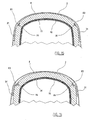
- the helmet 1 comprises, to absorb impacts, an inner shell 8, preferably of expanded polystyrene, which is generally covered with a covering comprising a soft layer 90, typically of sponge rubber, and a fabric layer 91 to lie in direct contact with the user's head.
- an inner shell 8 preferably of expanded polystyrene, which is generally covered with a covering comprising a soft layer 90, typically of sponge rubber, and a fabric layer 91 to lie in direct contact with the user's head.
- Said inner shell 8 has a concavity such as to cover at least the upper part of the cranium, and is associated with adjustment means to enlarge/contract said concavity, in order to adapt it to different cranium dimensions.
- Said adjustment means are operated by rotating the rear cap 3 about the front cap 2, and which when rotated towards its lowered position reduces the entry dimension B, to obtain simultaneous contraction of the inner shell 8.
- the inner shell 8 presents an upper region 80 fixed to the inner surface of the front cap 2, and is divided into an assembly of flexible segments 81 by a plurality of slots 82 extending radially from said upper region 80.
- the adjustment means comprise a strap 83 positioned as a belt surrounding all the flexible segments 81 in the upper region of the helmet 1, above the upper edge of the rear cap 3.
- Said strap 83 is contained in a guide channel 84 provided in the outer surfaces of the segments 81, and is inserted through a strap clamp 85 fixed to a first end of the strap 83, such that on pulling the second end, the strap 83 tightens onto the flexible segments 81, to cause them to flex simultaneously and hence contract the inner shell 8.
- the second end of the strap 83 is folded to hook shape and tightened about a pin 86 fixed to the rear cap 3, so that on rotating this latter about the front cap 2 towards its lowered position, said second end is simultaneously pulled to contract the inner shell 8.
- the strap 83 releases the flexible segments 81, which elastically tend to assume their undeformed configuration, hence enlarging the inner shell 8.
- the helmet 1 comprises at least one system 9 for guiding the rotation of the rear cap 3 about the front cap 2, making their engagement more stable and reliable and facilitating size adjustment.
- the helmet 1 comprises two separate mutually opposing guide systems 9 each positioned on a respective side of the helmet 1 and each comprising: a curved slot 88 provided in a projecting prolongation 21 of the front cap 2, and extending along a curved direction with its centre substantially on the transverse axis of rotation A; and a rigid pin 89 fixed to the rear cap 3 and projecting from its inner surface, to engage in said curved slot 88.
- each guide system 9 can be replaced by a guide system integrated into a respective locking device 4.
- said alternative guide system comprises a dovetail profile 54 projecting from that face of the rack 40 opposite the toothing, to slidingly engage in a matching groove 55 provided in a respective insert 56 fixed to the projecting prolongation 21 of the front cap 2.
Landscapes
- Helmets And Other Head Coverings (AREA)
Claims (18)
- Un casque de protection pour les sports et l'utilisation professionnelle, comprenant une coque externe rigide qui comprend elle-même une partie avant (2) avec une concavité capable de couvrir au moins la partie supérieure du crâne, et une partie arrière (3) avec une concavité capable de couvrir la partie arrière du crâne, où lesdites parties (2, 3) sont mobiles mutuellement afin de réduire ou d'augmenter la dimension d'entrée du casque (B) pour effectuer un ajustement de la taille, caractérisé par le fait que la partie arrière (3) est reliée de manière rotative à la partie avant (2) par deux dispositifs à charnière (32, 6) ayant des axes de rotation alignés, de manière à pivoter par rapport à cette dernière autour d'un axe (A) transversal au plan de symétrie vertical du crâne, placé dans une position substantiellement à l'intérieur de la région couvrant la partie du crâne à la limite entre le lobe pariétal et le lobe temporal.
- Un casque selon la revendication 1, caractérisé par le fait qu'au moins une partie (2, 3) comprend des rallonges respectives (21, 30), substantiellement en contact avec la surface intérieure de l'autre partie (2, 3) par coulissement mutuel, et disposées de manière à garantir la continuité de la coque externe du casque (1).
- Un casque selon la revendication 1, caractérisé par le fait que lesdites partie avant (2) et partie arrière (3) définissent ensemble la dimension d'entrée (B) qui varie par leur rotation mutuelle.
- Un casque selon la revendication 1, caractérisé par le fait qu'il comprend au moins un dispositif de verrouillage (4, 6) fournissant une action de verrouillage, pouvant être désengagé par contrôle manuel, qui empêche la rotation mutuelle entre la partie avant (2) et la partie arrière (3).
- Un casque selon la revendication 4, caractérisé par le fait qu'il comprend deux dispositifs de verrouillage en opposition mutuelle (4, 6), positionnés chacun sur une région latérale respective du casque (1).
- Un casque selon la revendication 5, caractérisé par le fait que le dispositif de verrouillage (4, 6) comprend :- une crémaillère (40, 69) solidaire avec l'une des parties (2, 3) ;- un élément cranté (51, 63) solidaire avec l'autre partie (2, 3) pour s'engager dans ladite crémaillère (40, 69) de manière à fournir une action de verrouillage qui empêche entre les parties (2, 3), dans au moins une direction ; et- un dispositif élastique (53, 74) qui maintient normalement l'élément cranté (51, 63) engagé dans la crémaillère (40, 69).
- Un casque selon la revendication 6, caractérisé par le fait que les dents de la crémaillère (40, 69) ont une forme en dent de scie pour permettre à la partie arrière (3) de pivoter autour de la partie avant (2), vers sa position abaissée.
- Un casque selon la revendication 6, caractérisé par le fait que le dispositif de verrouillage (4, 6) comprend :- une douille externe (44) fixée de manière solidaire avec la partie avant (2) ;- un ensemble bouton-poussoir (46) qui coulisse dans un siège axial (45) prévu dans ladite douille externe (44) et comprend un bouton supérieur (50) à enfoncer avec un doigt, et au moins une dent (51) positionnée de manière écartée et face au bouton supérieur (50) ;- une crémaillère (40) fixée de manière solidaire à la partie arrière (3) et dépassant de cette dernière, dont la portion en saille (43) s'engage dans un siège transversal (47) prévu dans ladite douille (44), de manière à coulisser entre la dent (51) et le bouton supérieur (50) de l'ensemble bouton-poussoir coulissant (46), avec sa denture face à la dent (51) ; et- un dispositif élastique (53) poussant l'ensemble bouton-poussoir (46) vers le haut de manière à pousser la dent (51) à s'engager avec la denture de la crémaillère (40).
- Un casque selon la revendication 6, caractérisé par le fait que le dispositif de verrouillage (4, 6) comprend :- un dispositif à charnière faisant pivoter la partie arrière (3) vers la partie avant (2) et comprenant un couvercle (61) fixé à l'une desdites parties (2, 3), et une douille cylindrique (60) qui est fixée à l'autre partie (2, 3), est retenue sur ledit couvercle (61) et libre de pivoter par rapport à ce dernier autour de son propre axe ;- une crémaillère circonférentielle à denture interne (69) coaxiale et solidaire avec ladite douille cylindrique (60) ;- un élément denté (63) solidaire avec ledit couvercle (61) et contenu dans ladite douille (60), comprenant au moins un bras élastique (74) qui porte au moins une dent (75) normalement engagée dans la denture de ladite crémaillère (69) ; et- un ensemble bouton-poussoir (64) doté d'un bouton supérieur (76) à enfoncer avec un doigt et comprenant un dispositif de contrôle (78) qui entraîne la flexion du bras (74) et le dégagement de la dent (75) lorsque l'ensemble bouton-poussoir (64) est enfoncé.
- Un casque selon la revendication 1, caractérisé par le fait qu'il comprend au moins un élément élastique (7) positionné pour relier la partie avant (2) à la partie arrière (3) de sorte à pousser la partie arrière (3) à pivoter autour de la partie avant (2), vers sa position levée.
- Un casque selon la revendication 1, caractérisé par le fait qu'il comprend, pour l'absorption des impacts, une coque interne (8) prévue pour rester interposée entre le crâne et la coque externe, et un dispositif d'ajustement (83) pour rétrécir/élargir ladite coque interne (8) afin de modifier son périmètre comprenant une sangle (83) qui entoure ce périmètre, disposant d'une première extrémité et d'une deuxième extrémité, de sorte qu'en tirant sur la deuxième extrémité, la sangle (83) se serre sur la coque interne (8) et rétrécit cette dernière, sous rotation de la partie arrière (3) par rapport à la partie avant (2).
- Un casque selon la revendication 11, caractérisé par le fait que ledit dispositif d'ajustement est contrôlé par la partie arrière (3) de la coque externe, de sorte que la rotation de cette dernière vers sa position abaissée entraîne le rétrécissement de la coque interne (8).
- Un casque selon la revendication 11, caractérisé par le fait que la coque interne (8) comprend une région supérieure (80) fixée à la partie avant (2) et d'où partent plusieurs fentes radiales (82) qui divisent la coque interne (8) en un ensemble de segments flexibles (81), où ladite sangle (83) qui entoure lesdits segments flexibles (81), possède une extrémité fixée à la partie arrière (3) et peut tirer les segments flexibles (81) les uns vers les autres afin de rétrécir la coque interne (8) ou, alternativement, peut relâcher lesdits segments flexibles (81) afin d'agrandir la coque interne (8).
- Un casque selon la revendication 13, caractérisé par le fait que la partie arrière (3) comprend deux pièces latérales (31) positionnées respectivement dans les régions latérales du casque (1) et se prolongeant dans les régions des tempes, pour rester interposées entre la partie avant (2) et la coque interne (8) ; lesdites pièces latérales (31) pivotant vers le haut de la partie avant (2) lors de la rotation de la partie arrière (3) vers sa position abaissée, afin d'occuper au moins partiellement l'espace laissé vide par le rétrécissement de la contraction de la coque interne (8).
- Un casque selon la revendication 1, caractérisé par le fait qu'il comprend, pour guider la rotation de la partie arrière (3) autour de la partie avant (2), au moins un système (9) comprenant deux parties à engagement mutuel (88, 89, 54, 55) coulissant l'une dans l'autre, dont une première partie (89, 55) est solidaire avec la partie avant (2) et une deuxième partie (88, 54) est solidaire avec la partie arrière (3).
- Un casque selon la revendication 15, caractérisé par le fait qu'il comprend deux systèmes de guidage à opposition mutuelle (9) chacun étant positionné sur une région latérale respective du casque (1).
- Un casque selon la revendication 16, caractérisé par le fait que le système de guidage (9) comprend une goupille rigide (89) fixée à la partie arrière (3) et se prolongeant à travers une fente (88) prévue dans la partie avant (2) et se prolonge dans une direction courbe avec son centre substantiellement sur l'axe de rotation transversal (A).
- Un casque selon la revendication 16, caractérisé par le fait que le système de guidage comprend un profilé saillant en queue-d'aronde (54) solidaire avec la partie arrière (3) et qui s'engage dans une fente correspondante (56) prévue dans la partie avant (2).
Applications Claiming Priority (2)
| Application Number | Priority Date | Filing Date | Title |
|---|---|---|---|
| IT000035A ITRE20050035A1 (it) | 2005-03-25 | 2005-03-25 | Casco di protezione ad uso sportivo e ad uso lavoro |
| PCT/EP2006/001682 WO2006099928A1 (fr) | 2005-03-25 | 2006-02-21 | Casque de protection pour faire du sport et pour travailler |
Publications (2)
| Publication Number | Publication Date |
|---|---|
| EP1860965A1 EP1860965A1 (fr) | 2007-12-05 |
| EP1860965B1 true EP1860965B1 (fr) | 2010-01-13 |
Family
ID=36283180
Family Applications (1)
| Application Number | Title | Priority Date | Filing Date |
|---|---|---|---|
| EP06707226A Expired - Lifetime EP1860965B1 (fr) | 2005-03-25 | 2006-02-21 | Casque de protection pour faire du sport et pour travailler |
Country Status (7)
| Country | Link |
|---|---|
| US (1) | US8146177B2 (fr) |
| EP (1) | EP1860965B1 (fr) |
| AT (1) | ATE454833T1 (fr) |
| CA (1) | CA2601526C (fr) |
| DE (1) | DE602006011719D1 (fr) |
| IT (1) | ITRE20050035A1 (fr) |
| WO (1) | WO2006099928A1 (fr) |
Families Citing this family (30)
| Publication number | Priority date | Publication date | Assignee | Title |
|---|---|---|---|---|
| ES2393747T3 (es) | 2005-11-23 | 2012-12-27 | Voztec Pty Ltd | Casco de protección |
| EP2076149B1 (fr) | 2006-10-13 | 2013-05-22 | The University Of British Columbia | Appareil servant à soulager un traumatisme de la colonne vertébrale |
| US8856973B2 (en) * | 2006-10-26 | 2014-10-14 | Sport Maska Inc. | Goalie helmet with novel strap configuration |
| US8296868B2 (en) | 2007-08-17 | 2012-10-30 | Easton Sports, Inc. | Adjustable hockey helmet |
| DE102007039287B4 (de) * | 2007-08-20 | 2009-10-08 | Rösler, Peter | Industrie-Stoßschutzkappe |
| IT1391276B1 (it) * | 2008-08-08 | 2011-12-01 | Dainese Spa | Casco perfezionato |
| WO2011025482A1 (fr) * | 2009-08-26 | 2011-03-03 | Warrior Sports, Inc. | Casque réglable et son procédé dutilisation |
| KR101126269B1 (ko) | 2009-09-24 | 2012-03-19 | 주식회사 홍진에이치제이씨 | 개폐장치 및 이를 포함하는 헬멧 |
| US8739318B2 (en) | 2010-09-03 | 2014-06-03 | Bauer Hockey, Inc. | Helmet comprising an occipital adjustment mechanism |
| EP2425730B1 (fr) * | 2010-09-03 | 2014-03-12 | Bauer Hockey Corp. | Casque comportant un mécanisme d'ajustement occipital |
| USD671687S1 (en) | 2011-03-03 | 2012-11-27 | Warrior Sports, Inc. | Helmet |
| US10306941B2 (en) | 2011-07-27 | 2019-06-04 | Bauer Hockey, Llc | Sports helmet with rotational impact protection |
| US9345282B2 (en) | 2011-07-27 | 2016-05-24 | Bauer Hockey, Inc. | Adjustable helmet for a hockey or lacrosse player |
| US20130067643A1 (en) * | 2011-09-16 | 2013-03-21 | Michael J. Musal | Adjustable sports helmet |
| US20130067645A1 (en) * | 2011-09-16 | 2013-03-21 | Easton Sports, Inc. | Adjustable sports helmet |
| USD669226S1 (en) | 2011-11-22 | 2012-10-16 | Warrior Sports, Inc. | Helmet |
| US20130247285A1 (en) * | 2012-03-26 | 2013-09-26 | The Cleveland Clinic Foundation | Football helmet |
| USD703387S1 (en) | 2013-06-26 | 2014-04-22 | Warrior Sports, Inc. | Helmet |
| US9161588B2 (en) * | 2013-10-21 | 2015-10-20 | Minson Enterprises Co., Ltd. | Adjustable headband device for a helmet |
| US10426213B2 (en) * | 2013-12-09 | 2019-10-01 | Kranos Ip Corporation | Total contact helmet |
| US10477909B2 (en) | 2013-12-19 | 2019-11-19 | Bauer Hockey, Llc | Helmet for impact protection |
| EP3091863B1 (fr) | 2014-01-06 | 2022-03-23 | Lisa Ferrara | Dispositifs composites pour fournir une protection contre une lésion tissulaire traumatique |
| US9961952B2 (en) | 2015-08-17 | 2018-05-08 | Bauer Hockey, Llc | Helmet for impact protection |
| KR101795452B1 (ko) * | 2016-03-17 | 2017-11-10 | 주식회사 기도스포츠 | 타입 가변형 헬멧 |
| WO2017213710A1 (fr) * | 2016-06-07 | 2017-12-14 | Bell Sports, Inc. | Corps de casque assemblés mécaniquement et procédé associé |
| US10710356B2 (en) * | 2017-03-30 | 2020-07-14 | Cranial Technologies, Inc. | Apparatus for point of service manufacture of custom cranial remodeling devices |
| US10609979B1 (en) * | 2017-09-13 | 2020-04-07 | Gerald F. Gallo | Adjustable safety helmet for motorsports |
| US11730227B2 (en) * | 2017-11-21 | 2023-08-22 | Bauer Hockey Llc | Adjustable helmet |
| US20220378140A1 (en) | 2021-05-28 | 2022-12-01 | Specialized Bicycle Components, Inc. | Bicycle helmet with modular impact absorbing structures |
| CN116421380A (zh) * | 2023-03-14 | 2023-07-14 | 浙江朗特医疗科技有限公司 | 一种便捷调节角度的手足两用矫正器 |
Family Cites Families (14)
| Publication number | Priority date | Publication date | Assignee | Title |
|---|---|---|---|---|
| US2861273A (en) * | 1957-02-21 | 1958-11-25 | Whitney A Stuart | Helmet with retractable annular shield |
| US2861274A (en) * | 1957-02-21 | 1958-11-25 | Whitney A Stuart | Three piece helmet |
| US3204251A (en) * | 1964-04-09 | 1965-09-07 | Spalding & Bros Of Canada Ltd | Hockey head protector |
| US3514787A (en) * | 1968-06-24 | 1970-06-02 | Kennedy Alvin B Jun | Collapsible protective hat |
| US3665514A (en) * | 1970-09-22 | 1972-05-30 | Us Army | Low profile size adjustable protective helmet |
| US3860966A (en) | 1973-03-19 | 1975-01-21 | Clarence Eugene Brown | Safety helmet |
| US3991422A (en) * | 1975-04-21 | 1976-11-16 | Hikogi Saotome | Defensive covering for the head |
| SE450620B (sv) * | 1982-11-01 | 1987-07-13 | Frosta Fritid Ab | Skyddshjelm med storleksjustering, spec for ishockey- och bandyspelare |
| US4607397A (en) * | 1984-09-27 | 1986-08-26 | Chevron Research Company | Portable hard hat |
| IT209878Z2 (it) * | 1987-01-30 | 1988-11-04 | Free Helmets S R L | Casco di protezione perfezionato del tipo a settori mobili. |
| CA2191693C (fr) | 1996-11-29 | 2005-11-08 | Daniel Chartrand | Casque ajustable avec mecanisme de verrouillage ameliore |
| US6108824A (en) | 1998-08-12 | 2000-08-29 | Sport Maska Inc. | Helmet adjustment mechanism with quick release |
| CA2321399C (fr) * | 2000-09-28 | 2005-07-26 | Bauer Nike Hockey Inc. | Casque protecteur avec rembourrage reglable |
| DE102004048839B4 (de) * | 2004-10-04 | 2006-07-20 | Schuberth Werk Gmbh | Integralhelm |
-
2005
- 2005-03-25 IT IT000035A patent/ITRE20050035A1/it unknown
-
2006
- 2006-02-21 CA CA2601526A patent/CA2601526C/fr not_active Expired - Fee Related
- 2006-02-21 WO PCT/EP2006/001682 patent/WO2006099928A1/fr not_active Ceased
- 2006-02-21 AT AT06707226T patent/ATE454833T1/de active
- 2006-02-21 EP EP06707226A patent/EP1860965B1/fr not_active Expired - Lifetime
- 2006-02-21 DE DE602006011719T patent/DE602006011719D1/de not_active Expired - Lifetime
- 2006-02-21 US US11/909,694 patent/US8146177B2/en not_active Expired - Fee Related
Also Published As
| Publication number | Publication date |
|---|---|
| EP1860965A1 (fr) | 2007-12-05 |
| ITRE20050035A1 (it) | 2006-09-26 |
| CA2601526C (fr) | 2014-06-03 |
| ATE454833T1 (de) | 2010-01-15 |
| CA2601526A1 (fr) | 2006-09-28 |
| WO2006099928A1 (fr) | 2006-09-28 |
| US20080189835A1 (en) | 2008-08-14 |
| US8146177B2 (en) | 2012-04-03 |
| DE602006011719D1 (de) | 2010-03-04 |
Similar Documents
| Publication | Publication Date | Title |
|---|---|---|
| US8146177B2 (en) | Protective helmet for sports use and for work use | |
| US6256798B1 (en) | Helmet with adjustable safety strap | |
| EP1781130B1 (fr) | Casque ajustable | |
| US8850624B2 (en) | Headgear with a spring buffered occipital cradle | |
| US3815155A (en) | Adjustable ear covers for safety hats | |
| JP6050748B2 (ja) | 保護ヘルメットのための内装構造体 | |
| EP2498636B1 (fr) | Casque de protection destiné notamment à des ouvriers forestiers | |
| EP3261475B1 (fr) | Couvre-chef doté d'un serre-nuque en élastomère auto-adaptable | |
| US4641382A (en) | Helmet fastening device | |
| EP3010361B1 (fr) | Casque de protection anti-relâchement, destiné en particulier à un usage sportif | |
| US7975318B2 (en) | Head strap | |
| EP0558559A1 (fr) | Casque de protection avec masque facial amovible | |
| US9622535B2 (en) | Helmets and helmet fit systems | |
| CA2916360C (fr) | Casque de hockey | |
| WO2006014823A2 (fr) | Mecanisme d'encliquetage flexible pour serre-tete de casque de protection | |
| US20060206994A1 (en) | Safety helmet and components thereof | |
| US12317947B2 (en) | Helmet and chin strap | |
| CN217039038U (zh) | 防护头盔 | |
| EP1871186B1 (fr) | Systeme de retenue pour casque et casque comprenant ledit systeme de retenue | |
| US20240148096A1 (en) | Two-Piece Chin Strap Pad | |
| WO2008139240A1 (fr) | Casque protecteur pour sportifs pourvu d'éléments protège-oreilles | |
| CN120322176A (zh) | 保护头盔 |
Legal Events
| Date | Code | Title | Description |
|---|---|---|---|
| PUAI | Public reference made under article 153(3) epc to a published international application that has entered the european phase |
Free format text: ORIGINAL CODE: 0009012 |
|
| 17P | Request for examination filed |
Effective date: 20070903 |
|
| AK | Designated contracting states |
Kind code of ref document: A1 Designated state(s): AT BE BG CH CY CZ DE DK EE ES FI FR GB GR HU IE IS IT LI LT LU LV MC NL PL PT RO SE SI SK TR |
|
| DAX | Request for extension of the european patent (deleted) | ||
| GRAP | Despatch of communication of intention to grant a patent |
Free format text: ORIGINAL CODE: EPIDOSNIGR1 |
|
| GRAS | Grant fee paid |
Free format text: ORIGINAL CODE: EPIDOSNIGR3 |
|
| GRAA | (expected) grant |
Free format text: ORIGINAL CODE: 0009210 |
|
| AK | Designated contracting states |
Kind code of ref document: B1 Designated state(s): AT BE BG CH CY CZ DE DK EE ES FI FR GB GR HU IE IS IT LI LT LU LV MC NL PL PT RO SE SI SK TR |
|
| REG | Reference to a national code |
Ref country code: GB Ref legal event code: FG4D |
|
| REG | Reference to a national code |
Ref country code: CH Ref legal event code: EP |
|
| REG | Reference to a national code |
Ref country code: IE Ref legal event code: FG4D |
|
| REF | Corresponds to: |
Ref document number: 602006011719 Country of ref document: DE Date of ref document: 20100304 Kind code of ref document: P |
|
| REG | Reference to a national code |
Ref country code: CH Ref legal event code: NV Representative=s name: ISLER & PEDRAZZINI AG |
|
| REG | Reference to a national code |
Ref country code: NL Ref legal event code: VDEP Effective date: 20100113 |
|
| LTIE | Lt: invalidation of european patent or patent extension |
Effective date: 20100113 |
|
| PG25 | Lapsed in a contracting state [announced via postgrant information from national office to epo] |
Ref country code: ES Free format text: LAPSE BECAUSE OF FAILURE TO SUBMIT A TRANSLATION OF THE DESCRIPTION OR TO PAY THE FEE WITHIN THE PRESCRIBED TIME-LIMIT Effective date: 20100424 Ref country code: NL Free format text: LAPSE BECAUSE OF FAILURE TO SUBMIT A TRANSLATION OF THE DESCRIPTION OR TO PAY THE FEE WITHIN THE PRESCRIBED TIME-LIMIT Effective date: 20100113 Ref country code: PT Free format text: LAPSE BECAUSE OF FAILURE TO SUBMIT A TRANSLATION OF THE DESCRIPTION OR TO PAY THE FEE WITHIN THE PRESCRIBED TIME-LIMIT Effective date: 20100513 Ref country code: IS Free format text: LAPSE BECAUSE OF FAILURE TO SUBMIT A TRANSLATION OF THE DESCRIPTION OR TO PAY THE FEE WITHIN THE PRESCRIBED TIME-LIMIT Effective date: 20100513 Ref country code: LT Free format text: LAPSE BECAUSE OF FAILURE TO SUBMIT A TRANSLATION OF THE DESCRIPTION OR TO PAY THE FEE WITHIN THE PRESCRIBED TIME-LIMIT Effective date: 20100113 |
|
| PG25 | Lapsed in a contracting state [announced via postgrant information from national office to epo] |
Ref country code: SI Free format text: LAPSE BECAUSE OF FAILURE TO SUBMIT A TRANSLATION OF THE DESCRIPTION OR TO PAY THE FEE WITHIN THE PRESCRIBED TIME-LIMIT Effective date: 20100113 Ref country code: PL Free format text: LAPSE BECAUSE OF FAILURE TO SUBMIT A TRANSLATION OF THE DESCRIPTION OR TO PAY THE FEE WITHIN THE PRESCRIBED TIME-LIMIT Effective date: 20100113 Ref country code: LV Free format text: LAPSE BECAUSE OF FAILURE TO SUBMIT A TRANSLATION OF THE DESCRIPTION OR TO PAY THE FEE WITHIN THE PRESCRIBED TIME-LIMIT Effective date: 20100113 Ref country code: FI Free format text: LAPSE BECAUSE OF FAILURE TO SUBMIT A TRANSLATION OF THE DESCRIPTION OR TO PAY THE FEE WITHIN THE PRESCRIBED TIME-LIMIT Effective date: 20100113 |
|
| PG25 | Lapsed in a contracting state [announced via postgrant information from national office to epo] |
Ref country code: EE Free format text: LAPSE BECAUSE OF FAILURE TO SUBMIT A TRANSLATION OF THE DESCRIPTION OR TO PAY THE FEE WITHIN THE PRESCRIBED TIME-LIMIT Effective date: 20100113 Ref country code: SE Free format text: LAPSE BECAUSE OF FAILURE TO SUBMIT A TRANSLATION OF THE DESCRIPTION OR TO PAY THE FEE WITHIN THE PRESCRIBED TIME-LIMIT Effective date: 20100113 Ref country code: RO Free format text: LAPSE BECAUSE OF FAILURE TO SUBMIT A TRANSLATION OF THE DESCRIPTION OR TO PAY THE FEE WITHIN THE PRESCRIBED TIME-LIMIT Effective date: 20100113 Ref country code: CY Free format text: LAPSE BECAUSE OF FAILURE TO SUBMIT A TRANSLATION OF THE DESCRIPTION OR TO PAY THE FEE WITHIN THE PRESCRIBED TIME-LIMIT Effective date: 20100113 Ref country code: BE Free format text: LAPSE BECAUSE OF FAILURE TO SUBMIT A TRANSLATION OF THE DESCRIPTION OR TO PAY THE FEE WITHIN THE PRESCRIBED TIME-LIMIT Effective date: 20100113 Ref country code: MC Free format text: LAPSE BECAUSE OF NON-PAYMENT OF DUE FEES Effective date: 20100301 Ref country code: GR Free format text: LAPSE BECAUSE OF FAILURE TO SUBMIT A TRANSLATION OF THE DESCRIPTION OR TO PAY THE FEE WITHIN THE PRESCRIBED TIME-LIMIT Effective date: 20100414 |
|
| PLBE | No opposition filed within time limit |
Free format text: ORIGINAL CODE: 0009261 |
|
| STAA | Information on the status of an ep patent application or granted ep patent |
Free format text: STATUS: NO OPPOSITION FILED WITHIN TIME LIMIT |
|
| PG25 | Lapsed in a contracting state [announced via postgrant information from national office to epo] |
Ref country code: BG Free format text: LAPSE BECAUSE OF FAILURE TO SUBMIT A TRANSLATION OF THE DESCRIPTION OR TO PAY THE FEE WITHIN THE PRESCRIBED TIME-LIMIT Effective date: 20100413 Ref country code: SK Free format text: LAPSE BECAUSE OF FAILURE TO SUBMIT A TRANSLATION OF THE DESCRIPTION OR TO PAY THE FEE WITHIN THE PRESCRIBED TIME-LIMIT Effective date: 20100113 Ref country code: CZ Free format text: LAPSE BECAUSE OF FAILURE TO SUBMIT A TRANSLATION OF THE DESCRIPTION OR TO PAY THE FEE WITHIN THE PRESCRIBED TIME-LIMIT Effective date: 20100113 |
|
| 26N | No opposition filed |
Effective date: 20101014 |
|
| GBPC | Gb: european patent ceased through non-payment of renewal fee |
Effective date: 20100413 |
|
| PG25 | Lapsed in a contracting state [announced via postgrant information from national office to epo] |
Ref country code: DK Free format text: LAPSE BECAUSE OF FAILURE TO SUBMIT A TRANSLATION OF THE DESCRIPTION OR TO PAY THE FEE WITHIN THE PRESCRIBED TIME-LIMIT Effective date: 20100113 Ref country code: IE Free format text: LAPSE BECAUSE OF NON-PAYMENT OF DUE FEES Effective date: 20100221 |
|
| PG25 | Lapsed in a contracting state [announced via postgrant information from national office to epo] |
Ref country code: GB Free format text: LAPSE BECAUSE OF NON-PAYMENT OF DUE FEES Effective date: 20100413 Ref country code: IT Free format text: LAPSE BECAUSE OF NON-PAYMENT OF DUE FEES Effective date: 20100221 |
|
| PGRI | Patent reinstated in contracting state [announced from national office to epo] |
Ref country code: IT Effective date: 20110616 |
|
| PGFP | Annual fee paid to national office [announced via postgrant information from national office to epo] |
Ref country code: IT Payment date: 20120229 Year of fee payment: 7 |
|
| PG25 | Lapsed in a contracting state [announced via postgrant information from national office to epo] |
Ref country code: HU Free format text: LAPSE BECAUSE OF FAILURE TO SUBMIT A TRANSLATION OF THE DESCRIPTION OR TO PAY THE FEE WITHIN THE PRESCRIBED TIME-LIMIT Effective date: 20100714 Ref country code: LU Free format text: LAPSE BECAUSE OF NON-PAYMENT OF DUE FEES Effective date: 20100221 |
|
| PG25 | Lapsed in a contracting state [announced via postgrant information from national office to epo] |
Ref country code: TR Free format text: LAPSE BECAUSE OF FAILURE TO SUBMIT A TRANSLATION OF THE DESCRIPTION OR TO PAY THE FEE WITHIN THE PRESCRIBED TIME-LIMIT Effective date: 20100113 |
|
| PGFP | Annual fee paid to national office [announced via postgrant information from national office to epo] |
Ref country code: DE Payment date: 20130227 Year of fee payment: 8 Ref country code: FR Payment date: 20130311 Year of fee payment: 8 Ref country code: CH Payment date: 20130225 Year of fee payment: 8 |
|
| PGFP | Annual fee paid to national office [announced via postgrant information from national office to epo] |
Ref country code: AT Payment date: 20130201 Year of fee payment: 8 |
|
| REG | Reference to a national code |
Ref country code: DE Ref legal event code: R119 Ref document number: 602006011719 Country of ref document: DE |
|
| REG | Reference to a national code |
Ref country code: CH Ref legal event code: PL |
|
| REG | Reference to a national code |
Ref country code: AT Ref legal event code: MM01 Ref document number: 454833 Country of ref document: AT Kind code of ref document: T Effective date: 20140221 |
|
| PG25 | Lapsed in a contracting state [announced via postgrant information from national office to epo] |
Ref country code: LI Free format text: LAPSE BECAUSE OF NON-PAYMENT OF DUE FEES Effective date: 20140228 Ref country code: CH Free format text: LAPSE BECAUSE OF NON-PAYMENT OF DUE FEES Effective date: 20140228 |
|
| REG | Reference to a national code |
Ref country code: FR Ref legal event code: ST Effective date: 20141031 |
|
| REG | Reference to a national code |
Ref country code: DE Ref legal event code: R119 Ref document number: 602006011719 Country of ref document: DE Effective date: 20140902 |
|
| PG25 | Lapsed in a contracting state [announced via postgrant information from national office to epo] |
Ref country code: AT Free format text: LAPSE BECAUSE OF NON-PAYMENT OF DUE FEES Effective date: 20140221 |
|
| PG25 | Lapsed in a contracting state [announced via postgrant information from national office to epo] |
Ref country code: FR Free format text: LAPSE BECAUSE OF NON-PAYMENT OF DUE FEES Effective date: 20140228 Ref country code: DE Free format text: LAPSE BECAUSE OF NON-PAYMENT OF DUE FEES Effective date: 20140902 |
|
| PG25 | Lapsed in a contracting state [announced via postgrant information from national office to epo] |
Ref country code: IT Free format text: LAPSE BECAUSE OF NON-PAYMENT OF DUE FEES Effective date: 20140221 |