EP1861828B1 - Machine a laver et procede de commande de la machine - Google Patents
Machine a laver et procede de commande de la machine Download PDFInfo
- Publication number
- EP1861828B1 EP1861828B1 EP06716117A EP06716117A EP1861828B1 EP 1861828 B1 EP1861828 B1 EP 1861828B1 EP 06716117 A EP06716117 A EP 06716117A EP 06716117 A EP06716117 A EP 06716117A EP 1861828 B1 EP1861828 B1 EP 1861828B1
- Authority
- EP
- European Patent Office
- Prior art keywords
- water
- heater
- water level
- water supply
- supply valve
- Prior art date
- Legal status (The legal status is an assumption and is not a legal conclusion. Google has not performed a legal analysis and makes no representation as to the accuracy of the status listed.)
- Expired - Lifetime
Links
Images


Classifications
-
- D—TEXTILES; PAPER
- D06—TREATMENT OF TEXTILES OR THE LIKE; LAUNDERING; FLEXIBLE MATERIALS NOT OTHERWISE PROVIDED FOR
- D06F—LAUNDERING, DRYING, IRONING, PRESSING OR FOLDING TEXTILE ARTICLES
- D06F39/00—Details of washing machines not specific to a single type of machines covered by groups D06F9/00 - D06F27/00
- D06F39/40—Steam generating arrangements
-
- D—TEXTILES; PAPER
- D06—TREATMENT OF TEXTILES OR THE LIKE; LAUNDERING; FLEXIBLE MATERIALS NOT OTHERWISE PROVIDED FOR
- D06F—LAUNDERING, DRYING, IRONING, PRESSING OR FOLDING TEXTILE ARTICLES
- D06F33/00—Control of operations performed in washing machines or washer-dryers
- D06F33/30—Control of washing machines characterised by the purpose or target of the control
- D06F33/32—Control of operational steps, e.g. optimisation or improvement of operational steps depending on the condition of the laundry
- D06F33/34—Control of operational steps, e.g. optimisation or improvement of operational steps depending on the condition of the laundry of water filling
-
- F—MECHANICAL ENGINEERING; LIGHTING; HEATING; WEAPONS; BLASTING
- F22—STEAM GENERATION
- F22B—METHODS OF STEAM GENERATION; STEAM BOILERS
- F22B1/00—Methods of steam generation characterised by form of heating method
- F22B1/28—Methods of steam generation characterised by form of heating method in boilers heated electrically
- F22B1/284—Methods of steam generation characterised by form of heating method in boilers heated electrically with water in reservoirs
-
- D—TEXTILES; PAPER
- D06—TREATMENT OF TEXTILES OR THE LIKE; LAUNDERING; FLEXIBLE MATERIALS NOT OTHERWISE PROVIDED FOR
- D06F—LAUNDERING, DRYING, IRONING, PRESSING OR FOLDING TEXTILE ARTICLES
- D06F2103/00—Parameters monitored or detected for the control of domestic laundry washing machines, washer-dryers or laundry dryers
- D06F2103/18—Washing liquid level
-
- D—TEXTILES; PAPER
- D06—TREATMENT OF TEXTILES OR THE LIKE; LAUNDERING; FLEXIBLE MATERIALS NOT OTHERWISE PROVIDED FOR
- D06F—LAUNDERING, DRYING, IRONING, PRESSING OR FOLDING TEXTILE ARTICLES
- D06F2105/00—Systems or parameters controlled or affected by the control systems of washing machines, washer-dryers or laundry dryers
- D06F2105/02—Water supply
-
- D—TEXTILES; PAPER
- D06—TREATMENT OF TEXTILES OR THE LIKE; LAUNDERING; FLEXIBLE MATERIALS NOT OTHERWISE PROVIDED FOR
- D06F—LAUNDERING, DRYING, IRONING, PRESSING OR FOLDING TEXTILE ARTICLES
- D06F2105/00—Systems or parameters controlled or affected by the control systems of washing machines, washer-dryers or laundry dryers
- D06F2105/28—Electric heating
Definitions
- the present invention relates to a washing machine, and higher particularly, to a steam generator for a washing machine, which generates steam so that the steam is used in a washing or drying operation.
- washing machines include a pulsator washing machine in which a drum is vertically erected, a drum washing machine in which a drum is horizontally laid, a drying and washing machine having drying and washing functions, and a drying machine having only a drying function.
- the pulsator washing machine the drum washing machine, and the drying and washing machine perform a washing operation using washing water.
- the steam generator assists the washing operation so that the washing operation is performed using a small amount of washing water.
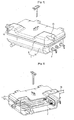
- the conventional steam generator comprises a case 1, and a heater 2.
- the case 1 defines the external appearance of the steam generator, forms a space for storing water required to generate steam, and comprises an upper case 11 forming the upper portion of the case 1 and a lower case 12 forming the lower portion of the case 1.
- a water supply pipe 1a connected to a water supply channel (not shown) of the washing machine is formed at one side of the case 1, and a steam discharge pipe 1b connected to a steam supply pipe (not shown) for supplying steam generated in the case 1 by evaporation to the inside of a drum of the washing machine is formed at the other side of the case 1.
- the heater 2 is installed in the horizontal direction in the lower portion of the case 1.
- the heater 2 is a sheath heater, and two terminals of the heater 2 are exposed from one side of the case 1 to the outside.
- the heater 2 serves to generate heat to evaporate water stored in the case 1.
- the heater 2 when the steam generator is operated, the heater 2 generates beat, and thus evaporates water stored in the case 1. Steam obtained by the evaporation of the water is discharged to the outside through the steam discharge pipe 1b, and is supplied to the inside of a drum (not shown) of the washing machine, thereby performing various operations using the steam.
- the point of time means a state in which a sufficient amount of water is supplied to the inside of the case 1.
- the conventional steam generator does not have a separate device for correctly measuring the supply amount of water in the steam generator according to respective states, but only has a water level sensor for detecting whether or not water exists in the steam generator. ,
- the washing machine having the conventional steam generator is operated when water exists in the steam generator regard lower of the supply amount of the water in the steam generator. Accordingly, during the operation of the steam generator, a lack of water occurs and the heater 2 is exposed to external air.
- EP 1 507 031 Al describes a washing machine having a steam generator, which generates steam so that the steam is used in a washing or drying operation.
- the steam generator includes a case having a space for storing water; a heater provided in the space of the case for generating heat; and a water level sensor for sensing the minimum and maximum level of the water stored in the space of the case.
- a controller controls the water supply valve and the heater according to a result sensed by the water level sensor.
- the water supply valve is opened and closed, thereby controlling the supply of water to the steam generator.
- An object of the present invention devised to solve the problem lies on a washing machine having a steam generator, in which the correct amount of water supplied to the inside of a case is sensed so that operations of various components for generating steam can be controlled using the sensed value, and a method for controlling the same.
- a controller controls the water supply valve and the heater according to a result sensed by the water level sensor.
- the water supply valve is opened and closed, thereby controlling the supply of water to the steam generator.
- the water level sensor may sense whether or not the level of the water is lower than the minimun water level or higher than the maximum water level. Further, the water level sensor may be operated such that both methods are possible.
- the minimum water level may be a level of water, which exposes the heater from the surface of the water. That is, preferably, the minimum water level may be set to be equal to or lower than the level of water, which exposes the heater from the surface of the water.
- the operation of the heater is stopped.
- the maximum water level is a level of water, which is maximally , contained in the space of the case.
- the water supply valve is closed.
- the controller closes the water supply valve when a water supply time counted after the start of the supply of water reaches a designated time. Thereby, it is possible to prepare for a defect of the water level sensor.
- the controller closes the water supply valve and operates a warning device to notify a user of the defect of the water level sensor, when the result sensed by the water level sensor is not higher than the maximum water level although the counted water supply time exceeds the designated time.
- the warning device may have various shapes.
- the warning device is a buzzer for sounding an alarm, a lamp, or an LCD for displaying the defect.
- the controller starts the operation of the heater only when the result sensed by the water level sensor is equal to or higher than the maximum water level. Then, the controller stops the operation of the heater when a heater operating time counted after the start of the operation of the heater reaches a designated time. Thereby, it is possible to prepare for a defect of the water level sensor.
- the controller stops the operation of the heater and operates the warning device to notify a user of the defect of the water level sensor, when the result sensed by the water level sensor is not lower than the minimum water level although the heater operating time counted after the start of the operation of the heater exceeds the designated time.
- the water level sensor comprises a long electrode, a terminal of which is exposed to a height corresponding to the minimum water level; a common electrode, a terminal of which is exposed to a height corresponding to or below the minimum water level; and a short electrode, a terminal of which is exposed to a height corresponding to the maximum water level.
- the water level sensor has various water level sensing methods. For example, voltages values of the short and long electrodes based on the common electrode may be used, or whether or not the common electrode is electrically connected to the long or short electrode may be used.
- the water level sensor is out of order, the supply of water or the generation of heat is automatically stopped according to the total water supply time or the total heat generating time, thereby improving the stability of the steam generator.
- FIG. 1 is a perspective view of a conventional steam generator for a washing machine
- FIG. 2 is an exploded perspective view illustrating the internal structure of the conventional steam generator
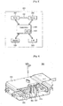
- FIG. 3 is a block diagram illustrating a washing machine in accordance with an embodiment of the present invention.
- FIG. 4 is an exploded perspective view illustrating the internal structure of a steam generator for the washing machine in accordance with the embodiment of the present invention
- FIGS. 5 and 6 are flow charts illustrating a method for controlling the washing machine in accordance with the embodiment of the present invention.
- FIGS. 7 to 11 are schematic views of a water level sensor for illustrating the method for controlling the washing machine in accordance with the embodiment of the present invention.
- FIG. 3 is a block diagram illustrating a washing machine in accordance with the embodiment of the present invention.
- the washing machine in accordance with the embodiment of the present invention comprises a main body 100, a water supply valve 200, a steam generator 300, and a controller 400.
- the main body 100 of the washing machine forms the external, appearance of the washing machine.
- the water supply valve 200 of the washing machine is provided in a water supply channel 110 in the main body 100, and selectively opens and closes the water supply channel 110.
- the water supply channel 110 serves to guide the supply of water, which is used to generate steam, to the steam generator 300.
- the steam generator 300 of the washing machine is provided in one space in the main body 100, and serves to generate steam by evaporating the water supplied through the water supply channel 110.
- the steam generator 300 as shown in FIG. 4 , comprises a case 310, a heater 320, and a water level sensor 330.
- the case 310 is a rectangular box for forming the external appearance of the steam generator 300 and forming a space in which steam is generated.
- the heater 320 is provided in the case 310, and serves to evaporate water stored in the case 310 by generating heat.
- the water level sensor 330 comprises three electrodes, such as a common electrode 331, a long electrode 332, and a short electrode 333, and serves to sense a water level in the case 310.
- the common electrode 331 and the long electrode 332 are installed such that terminals of the common electrode 331 and the long electrode 332 are exposed at a height corresponding to the minimum level of water necessary to generate steam, and the short electrode 333 has a shorter length than those of the common electrode 331 and the long electrode 332 and is installed such that a terminal of the short electrode 333 is exposed at a height corresponding to the maximum level of the water necessary to generate steam.
- the height, at which the terminals of the long electrode 332 and the common electrode 331 are exposed, is a height, at which the heater 320 is completely submerged in water.
- the controller 400 of the washing machine is provided in the main body 100, and controls the operations of various driving units of the washing machine, the operation of the water supply valve 200, and the generation of heat from the heater 320 of the steam generator 300.
- the controller 400 comprises an analog-digital converter (ADC) 410 for converting a value sensed by the water level sensor 330 of the steam generator 300 into a digital data value.
- ADC analog-digital converter
- the controller 400 compares the digital data value (hereinafter, referred to as a "converted value", which is converted by the ADC 410, to a predetermined reference value, and controls the operation of the water supply valve 200 and the generation of heat from the heater 320 based on the compared result.
- the above washing machine in accordance with the embodiment of the present invention may be a drum washing machine exclusively having a washing function, a drum washing machine having washing and drying functions, or a drying machine.
- the washing machine in accordance with the embodiment of the present invention further comprises a control panel (C/P) 510 allowing a user to manipulate various operations, and a display unit 520 displaying the manipulated operations and various states of the washing machine.
- C/P control panel
- the controller 400 of the washing machine confirms whether or not an external signal for selecting various operations is supplied from a user through the C/P 510 (S110).
- the controller 400 receives a signal generated by the above selection.
- the controller 400 controls the water level sensor 330 of the steam generator 300 so that the water level sensor 330 senses a water level in the case 310, and then receives sensed values from the water level sensor 330 (S120).
- the sensed values are voltage values of the long electrode 332 and the short electrode 333.
- the controller 400 converts the received voltage values of the long electrode 332 and the short electrode 333 into digital data values using the ADC 410 (S130), and confirms the converted values.
- the controller 400 compares the converted values to a predetermined reference value (S 140).
- the controller 400 determines whether or not the converted values of the long electrode 332 and the short electrode 333 are larger than, equal to, or smaller than 150.
- the controller 400 determines whether or not the water supply valve 200 is operated and the heater 320 is operated based on the compared result (S150), and performs the control according to the determined result (S160).
- step S150 and the step S160 are described in higher detail.
- the controller 400 determines that the amount of water in the case 310 of the steam generator 300 is insufficient (S210). This state is illustrated in FIGS. 7 to 10 .
- the controller 400 determines that the amount of water in the case 310 of the steam generator 300 is insufficient.
- the controller 400 opens the water supply valve 200 so that water is supplied to the steam generator 300. At this time, the controller 400 does not operate the heater 320.
- water is supplied to the steam generator 300 through the water supply channel 110 of the main body 100 of the washing machine, and the heater 320 is maintained in an OFF state (S220).
- the controller 400 continuously compares the converted values (L and S) of the long and short electrodes 332 and 333 to the reference value (N), and, when the converted value (S) of the short electrode 333 is smaller than the reference value (N), the controller 400 closes the water supply valve 200 so that the supply of water is stopped (S230). This state is illustrated in FIG. 11 .
- the converted value (S) of the short electrode 333 and/or the converted value (L) of the long electrode 332 are/is larger than the reference value (N).
- the controller 400 counts the time during the above water supply process.
- the water supply valve 200 is closed so that the supply of water is stopped.
- the designated time is a time to supply water to a full water level in the case 310, i.e., a position at which the short electrode 333 is located, when the water is supplied to the inside of the case 310 under the condition that the water supply valve 200 is opened, and was obtained from conventional experiments.
- an error message indicating the defect of the water level sensor 330 is displayed on the display unit 520, thus informing a user of the defect.
- the controller 400 closes the water supply valve 200 and turns the heater 320 on (S250), thereby operating the steam generator 300 so that steam is supplied to a drum of the washing machine.
- the sensing of the water level in the case 310 using the water level sensor 330 is continuously performed during the operation of the steam generator 300, i.e., during the generation of heat from the heater 320.
- the above operation of the steam generator 300 is continuously performed until the operation of the washing machine using steam is terminated.
- the operation of the heater 320 is forcibly stopped even if the operation of the washing machine using steam is not terminated (S260), and then water is additionally supplied to the steam generator 300.
- the water level sensor 330 may be out of order.
- the water level in the case 310 is lowered lower than the height of the heater 320 and the heater 320 is superheated, thus causing many problems.
- the controller 400 counts the time during the operation of the steam generator 300.
- the converted value (L) of the long electrode 332 does not vary although the heat generating time of the heater 320 exceeds a designated time set from a point of time, when water is finally supplied to the steam generator 300, the operation of the heater 320 is stopped so that the generation of heat from the heater 320 is stopped.
- the designated time is a time to lower the water level in the case 310 to a , position at which the terminal of the long electrode 332 is located; when the heater 320 generates heat under the condition that the water level in the case 310 reaches the full water level, and was obtained from conventional experiments.
- the heat generating time of the heater 320 is the total of time during the turning-on of the heater 320.
- an error message indicating the defect of the water level sensor 330 is displayed on the display unit 520, thus informing a user of the defect.
- the converted values (L and S) of the long electrode 332 and the short electrode 333 vary.
- the converted value (L) of the long electrode 332 may become smaller than the reference value (N) before the converted value (S) of the short electrode 333 becomes smaller than the reference value (N).
- This point of time is programmed for controlling the steam generator 300.
- the process for supplying water to the steam generator 300 and the process for generating heat from the heater 320 are distinguished from each other. Accordingly, when the water supplying process is performed, the supply of water is controlled using the converted value (S) of the short electrode 333 regardlower of the variation of the converted value (L) of the long electrode 332, and when the heat generating process is performed, the generation of heat is controlled using the converted value (L) of the long electrode 332 regardlower of the variation of the converted value (S) of the short electrode 333.
- the heater 302 does not generate heat, and, during the generation of heat, although the converted value (S) of the short electrode 333 becomes larger than the reference value (N), the supply of water is not performed.
- the present invention provides a washing machine having a steam generator, which generates steam so that the steam is used in a washing or drying operation, and a method for controlling the same.
- the water level sensor is out of order, the supply of water or the generation of heat is automatically stopped according to the total water supply time or the total heat generating time, thereby improving the stability of the steam generator.
Landscapes
- Engineering & Computer Science (AREA)
- Textile Engineering (AREA)
- Life Sciences & Earth Sciences (AREA)
- Sustainable Development (AREA)
- Sustainable Energy (AREA)
- Physics & Mathematics (AREA)
- Thermal Sciences (AREA)
- Mechanical Engineering (AREA)
- General Engineering & Computer Science (AREA)
- Control Of Washing Machine And Dryer (AREA)
- Cleaning By Liquid Or Steam (AREA)
- Detergent Compositions (AREA)
Claims (15)
- Machine à laver, machine à sécher et à laver ou machine à sécher, comprenant :un générateur de vapeur (300) incluant un carter (310) comportant un espace pour stocker de l'eau et un élément chauffant (320) prévu dans l'espace du carter (310) ;un contrôleur (400) adapté à commander le fonctionnement de la machine ; etun robinet d'alimentation en eau (200) relié au générateur de vapeur (300),dans laquelle le générateur de vapeur (300) comporte un détecteur de niveau d'eau (330) pour détecter le niveau minimum et le niveau maximum de l'eau stockée dans l'espace du carter (310), etle contrôleur (400) est adapté à commander le robinet d'alimentation en eau (200) ou l'élément chauffant (320) en fonction du résultat détecté par le détecteur de niveau d'eau (330),caractérisée en ce que
le contrôleur (400) est adapté à arrêter le fonctionnement de l'élément chauffant (320) lorsque le temps de fonctionnement de l'élément chauffant compté à partir du début du fonctionnement de l'élément chauffant (320) atteint un temps désigné dans le cas où le détecteur de niveau d'eau (330) présente un dysfonctionnement ou est hors service et/ou le contrôleur (400) est adapté à fermer le robinet d'alimentation en eau (200) lorsque le temps d'alimentation en eau compté à partir du début de l'alimentation en eau atteint un temps désigné dans le cas où le détecteur de niveau d'eau (330) présente un dysfonctionnement ou est hors service. - Machine à laver selon la revendication 1, dans laquelle le niveau d'eau minimum est un niveau d'eau auquel est exposé l'élément chauffant (320) par rapport à la surface de l'eau.
- Machine à laver selon la revendication 1, dans laquelle le détecteur de niveau d'eau (330) comprend :une électrode longue (332), dont une borne est exposée à une hauteur correspondant au niveau d'eau minimum ;une électrode commune (331), dont une borne est exposée à une hauteur correspondant au niveau d'eau minimum ou en dessous ; etune électrode courte (333), dont une borne est exposée à une hauteur correspondant au niveau d'eau maximum.
- Machine à laver selon la revendication 1, dans laquelle le contrôleur (400) est adapté à arrêter le fonctionnement de l'élément chauffant (320) lorsque le niveau détecté de l'eau stockée dans l'espace du carter (310) est plus bas que le niveau d'eau minimum.
- Machine à laver selon la revendication 1, dans laquelle le contrôleur (400) est adapté à fermer le robinet d'alimentation en eau (200) lorsque le niveau détecté de l'eau stockée dans l'espace du carter (310) est plus haut que le niveau d'eau maximum.
- Machine à laver selon la revendication 1, dans laquelle le contrôleur (400) est adapté à ouvrir le robinet d'alimentation en eau (200) pour commencer à fournir de l'eau au générateur de vapeur (300), à compter le temps d'alimentation en eau et à fermer le robinet d'alimentation en eau (200) lorsque le temps d'alimentation en eau compté atteint un temps désigné.
- Machine à laver selon la revendication 6, dans laquelle le contrôleur (400) est adapté à fermer le robinet d'alimentation en eau (200) lorsque le temps d'alimentation en eau compté à partir du début de l'alimentation en eau atteint un temps désigné, alors que le résultat détecté par le détecteur de niveau d'eau n'est pas supérieur au niveau d'eau maximum.
- Machine à laver selon la revendication 7, comprenant en outre un dispositif d'avertissement,
dans laquelle le contrôleur (400) est adapté à fermer le robinet d'alimentation en eau (200) et à déclencher le dispositif d'avertissement lorsque le résultat détecté par le détecteur de niveau d'eau (330) n'est pas supérieur au niveau d'eau maximum, alors que le temps d'alimentation en eau compté à partir du début de l'alimentation en eau dépasse un temps désigné. - Machine à laver selon la revendication 1, dans laquelle le contrôleur (400) est adapté à démarrer le fonctionnement de l'élément chauffant (320) seulement lorsque le résultat détecté par le détecteur de niveau d'eau (330) est supérieur au niveau d'eau maximum.
- Machine à laver selon la revendication 1, comprenant en outre un dispositif d'avertissement,
dans laquelle le contrôleur (400) est adapté à arrêter le fonctionnement de l'élément chauffant (320) et à déclencher le dispositif d'avertissement lorsque le résultat détecté par le détecteur de niveau d'eau (330) n'est pas inférieur au niveau d'eau minimum, alors que le temps de fonctionnement de l'élément chauffant compté à partir du démarrage du fonctionnement de l'élément chauffant (320) dépasse un temps désigné. - Machine à laver selon la revendication 1, dans laquelle le contrôleur (400) comprend un convertisseur (410) pour convertir la valeur détectée par le détecteur de niveau d'eau (330) en une valeur de donnée numérique, comparer la valeur de donnée numérique convertie par le convertisseur (410) a une valeur de référence prédéterminée et commander le fonctionnement du robinet d'alimentation en eau (200) et la génération de chaleur depuis l'élément chauffant (320), en se basant sur le résultat de la comparaison.
- Procédé de commande d'une machine à laver, d'une machine à sécher et à laver ou d'une machine à sécher et comportant un générateur de vapeur (300), comprenant les étapes consistant à :confirmer (S110) si un signal extérieur pour commander le fonctionnement d'un robinet d'alimentation en eau (200) et d'un élément chauffant (320) est appliqué ou non ;détecter (S 120) la valeur de tension d'une électrode longue (332) ou d'une électrode courte (333), en utilisant un détecteur de niveau d'eau (330) d'un générateur de vapeur (300), lorsqu'il est confirmé que le signal de commande est appliqué ;convertir (S130) la valeur de tension en une valeur de signal numérique et comparer (S 140) la valeur convertie à une valeur de référence prédéterminée ;déterminer (S 150) si le robinet d'alimentation en eau (200) et l'élément chauffant (320) sont actionnés ou non, en fonction du résultat de la comparaison et commander (S 160) le fonctionnement du robinet d'alimentation en eau (200) et de l'élément chauffant (320), en se basant sur le résultat déterminé ;compter le temps de génération de chaleur de l'élément chauffant (320) pendant la commande de génération de chaleur depuis l'élément chauffant (320) et arrêter la génération de chaleur depuis l'élément chauffant (320) lorsque le temps de génération de chaleur compté atteint un temps désigné dans le cas où le détecteur de niveau d'eau (330) présente un dysfonctionnement ou est hors service ;
et/oucompter le temps d'alimentation en eau pendant la commande du robinet d'alimentation en eau (200) et fermer le robinet d'alimentation en eau (200) lorsque le temps d'alimentation en eau compté atteint un temps désigné dans le cas où le détecteur de niveau d'eau (330) présente un dysfonctionnement ou est hors service. - Procédé selon la revendication 12, dans lequel, lors de la commande du fonctionnement du robinet d'alimentation en eau (200) et de l'élément chauffant (320) basée sur le résultat déterminé, la commande du fonctionnement du robinet d'alimentation en eau (200) est effectuée lorsque la valeur convertie de l'électrode courte (333) est plus grande que la valeur de référence, à condition que la génération de chaleur par l'élément chauffant (320) ne soit pas effectuée.
- Procédé selon la revendication 13, dans lequel le fonctionnement du robinet d'alimentation en eau (200) est effectué en continu jusqu'à ce que la valeur convertie de l'électrode courte (333) soit plus petite que la valeur de référence.
- Procédé selon la revendication 14, comprenant en outre les étapes consistant à :compter le temps de fonctionnement du robinet d'alimentation en eau (200) et confirmer si la valeur convertie d'au moins une électrode varie ou non ; etarrêter le fonctionnement du robinet d'alimentation en eau (200) lorsque la valeur convertie de l'au moins une électrode ne varie pas jusqu'à ce que le temps de fonctionnement du robinet d'alimentation en eau (200) dépasse un temps désigné.
Applications Claiming Priority (2)
| Application Number | Priority Date | Filing Date | Title |
|---|---|---|---|
| KR1020050025102A KR100672526B1 (ko) | 2005-03-25 | 2005-03-25 | 세탁 장치 및 그 제어 방법 |
| PCT/KR2006/000667 WO2006101312A1 (fr) | 2005-03-25 | 2006-02-27 | Machine a laver et procede de commande de la machine |
Publications (2)
| Publication Number | Publication Date |
|---|---|
| EP1861828A1 EP1861828A1 (fr) | 2007-12-05 |
| EP1861828B1 true EP1861828B1 (fr) | 2011-04-13 |
Family
ID=37023949
Family Applications (1)
| Application Number | Title | Priority Date | Filing Date |
|---|---|---|---|
| EP06716117A Expired - Lifetime EP1861828B1 (fr) | 2005-03-25 | 2006-02-27 | Machine a laver et procede de commande de la machine |
Country Status (7)
| Country | Link |
|---|---|
| US (1) | US8122742B2 (fr) |
| EP (1) | EP1861828B1 (fr) |
| KR (1) | KR100672526B1 (fr) |
| CN (1) | CN1977292B (fr) |
| AT (1) | ATE505578T1 (fr) |
| DE (1) | DE602006021288D1 (fr) |
| WO (1) | WO2006101312A1 (fr) |
Families Citing this family (37)
| Publication number | Priority date | Publication date | Assignee | Title |
|---|---|---|---|---|
| EP1862581B2 (fr) * | 2006-06-01 | 2020-09-09 | Electrolux Home Products Corporation N.V. | Procédé destiné à l'utilisation d'un appareil ménager, particulièrement un sécheur où une machine à laver, et un appareil ménager |
| US7941885B2 (en) | 2006-06-09 | 2011-05-17 | Whirlpool Corporation | Steam washing machine operation method having dry spin pre-wash |
| US7730568B2 (en) | 2006-06-09 | 2010-06-08 | Whirlpool Corporation | Removal of scale and sludge in a steam generator of a fabric treatment appliance |
| US7627920B2 (en) | 2006-06-09 | 2009-12-08 | Whirlpool Corporation | Method of operating a washing machine using steam |
| US7765628B2 (en) | 2006-06-09 | 2010-08-03 | Whirlpool Corporation | Steam washing machine operation method having a dual speed spin pre-wash |
| US7665332B2 (en) | 2006-08-15 | 2010-02-23 | Whirlpool Corporation | Steam fabric treatment appliance with exhaust |
| US7681418B2 (en) | 2006-08-15 | 2010-03-23 | Whirlpool Corporation | Water supply control for a steam generator of a fabric treatment appliance using a temperature sensor |
| US7841219B2 (en) | 2006-08-15 | 2010-11-30 | Whirlpool Corporation | Fabric treating appliance utilizing steam |
| US7591859B2 (en) | 2006-08-15 | 2009-09-22 | Whirlpool Corporation | Water supply control for a steam generator of a fabric treatment appliance using a weight sensor |
| US7886392B2 (en) | 2006-08-15 | 2011-02-15 | Whirlpool Corporation | Method of sanitizing a fabric load with steam in a fabric treatment appliance |
| US7707859B2 (en) | 2006-08-15 | 2010-05-04 | Whirlpool Corporation | Water supply control for a steam generator of a fabric treatment appliance |
| US7753009B2 (en) | 2006-10-19 | 2010-07-13 | Whirlpool Corporation | Washer with bio prevention cycle |
| KR101319874B1 (ko) | 2006-12-22 | 2013-10-18 | 엘지전자 주식회사 | 건조기의 제어방법 |
| US8393183B2 (en) | 2007-05-07 | 2013-03-12 | Whirlpool Corporation | Fabric treatment appliance control panel and associated steam operations |
| KR100857801B1 (ko) | 2007-05-09 | 2008-09-09 | 엘지전자 주식회사 | 스팀건조기의 제어방법 |
| DE102008026114B4 (de) * | 2007-06-08 | 2020-08-06 | Lg Electronics Inc. | Steuerungsverfahren für einen Dampfgenerator sowie Bekleidungsbehandlungsmaschine mit diesem |
| US8555676B2 (en) | 2007-08-31 | 2013-10-15 | Whirlpool Corporation | Fabric treatment appliance with steam backflow device |
| US7861343B2 (en) | 2007-08-31 | 2011-01-04 | Whirlpool Corporation | Method for operating a steam generator in a fabric treatment appliance |
| US7690062B2 (en) | 2007-08-31 | 2010-04-06 | Whirlpool Corporation | Method for cleaning a steam generator |
| US8037565B2 (en) | 2007-08-31 | 2011-10-18 | Whirlpool Corporation | Method for detecting abnormality in a fabric treatment appliance having a steam generator |
| US7905119B2 (en) | 2007-08-31 | 2011-03-15 | Whirlpool Corporation | Fabric treatment appliance with steam generator having a variable thermal output |
| US7918109B2 (en) | 2007-08-31 | 2011-04-05 | Whirlpool Corporation | Fabric Treatment appliance with steam generator having a variable thermal output |
| US8555675B2 (en) | 2007-08-31 | 2013-10-15 | Whirlpool Corporation | Fabric treatment appliance with steam backflow device |
| US7966683B2 (en) | 2007-08-31 | 2011-06-28 | Whirlpool Corporation | Method for operating a steam generator in a fabric treatment appliance |
| KR101430477B1 (ko) | 2008-04-01 | 2014-08-18 | 엘지전자 주식회사 | 의류처리장치의 제어방법 |
| KR101440295B1 (ko) * | 2008-08-13 | 2014-09-15 | 동부대우전자 주식회사 | 드럼 세탁기 스팀 제어 장치 및 방법 |
| KR101440296B1 (ko) * | 2008-08-13 | 2014-09-15 | 동부대우전자 주식회사 | 드럼 세탁기 스팀 제어 방법 |
| EP2623662B1 (fr) | 2012-02-06 | 2018-04-04 | LG Electronics Inc. | Machine de blanchisserie et procédé de commande correspondant |
| KR101443647B1 (ko) * | 2012-05-31 | 2014-09-23 | 엘지전자 주식회사 | 세탁기 제어방법 |
| US10640909B2 (en) * | 2016-01-04 | 2020-05-05 | John McCLOY | Washing machine fill reservoir |
| KR102367886B1 (ko) * | 2017-04-14 | 2022-02-25 | 엘지전자 주식회사 | 의류 처리 장치 |
| CN108793269B (zh) * | 2017-04-27 | 2021-06-22 | 芜湖美的厨卫电器制造有限公司 | 净水器水袋的水位控制方法和净水器 |
| CN109422301A (zh) * | 2017-08-22 | 2019-03-05 | 芜湖美的厨卫电器制造有限公司 | 净水器水袋的水位控制方法和净水器 |
| CN109422302A (zh) * | 2017-08-22 | 2019-03-05 | 芜湖美的厨卫电器制造有限公司 | 净水器水袋的水位控制方法和净水器 |
| CN109422300A (zh) * | 2017-08-22 | 2019-03-05 | 芜湖美的厨卫电器制造有限公司 | 净水器水袋的水位控制方法和净水器 |
| CN114263024B (zh) * | 2020-09-15 | 2025-09-30 | 云米互联科技(广东)有限公司 | 一种蒸汽发生器的壳体结构、洗衣机 |
| JP7723570B2 (ja) * | 2021-10-19 | 2025-08-14 | シャープ株式会社 | 蒸気発生装置及び加熱調理器 |
Family Cites Families (14)
| Publication number | Priority date | Publication date | Assignee | Title |
|---|---|---|---|---|
| US1507032A (en) * | 1923-03-31 | 1924-09-02 | Gen Fireproofing Co | Process of fabricating fire-resisting safes |
| US3805561A (en) * | 1972-06-29 | 1974-04-23 | Cissell W Mfg Co | Garment finishing apparatus |
| DD241941B1 (de) | 1985-10-21 | 1989-04-26 | Berlin Oberbekleidung | Sicherheitsvorrichtung fuer einen transportablen kleindampferzeuger |
| KR100517613B1 (ko) * | 2003-03-31 | 2005-09-28 | 엘지전자 주식회사 | 증기분사식 드럼세탁기 |
| KR100510680B1 (ko) * | 2003-03-31 | 2005-08-31 | 엘지전자 주식회사 | 증기분사식 드럼세탁기 |
| KR100550543B1 (ko) | 2003-08-07 | 2006-02-10 | 엘지전자 주식회사 | 드럼 세탁기의 제어 방법 |
| KR100540749B1 (ko) * | 2003-08-13 | 2006-01-10 | 엘지전자 주식회사 | 드럼세탁기용 증기발생장치 |
| KR20050017490A (ko) * | 2003-08-13 | 2005-02-22 | 엘지전자 주식회사 | 드럼 세탁기용 증기 세탁 방법 |
| KR100500887B1 (ko) | 2003-08-13 | 2005-07-14 | 엘지전자 주식회사 | 드럼 세탁기의 증기발생장치 및 그 방법 |
| KR100666318B1 (ko) * | 2003-08-13 | 2007-01-10 | 엘지전자 주식회사 | 드럼세탁기용 증기발생장치 |
| US7600402B2 (en) * | 2003-11-04 | 2009-10-13 | Lg Electronics Inc. | Washing apparatus and control method thereof |
| KR100565251B1 (ko) | 2004-07-19 | 2006-03-30 | 엘지전자 주식회사 | 드럼세탁기의 절수세탁방법 |
| US8122547B2 (en) * | 2004-07-20 | 2012-02-28 | Lg Electronics Inc. | Washing machine and method for controlling the same |
| KR100698147B1 (ko) * | 2005-02-25 | 2007-03-26 | 엘지전자 주식회사 | 세탁기의 제어방법 |
-
2005
- 2005-03-25 KR KR1020050025102A patent/KR100672526B1/ko not_active Expired - Fee Related
-
2006
- 2006-02-27 WO PCT/KR2006/000667 patent/WO2006101312A1/fr not_active Ceased
- 2006-02-27 EP EP06716117A patent/EP1861828B1/fr not_active Expired - Lifetime
- 2006-02-27 CN CN2006800003709A patent/CN1977292B/zh not_active Expired - Lifetime
- 2006-02-27 US US11/628,322 patent/US8122742B2/en active Active
- 2006-02-27 DE DE602006021288T patent/DE602006021288D1/de not_active Expired - Lifetime
- 2006-02-27 AT AT06716117T patent/ATE505578T1/de not_active IP Right Cessation
Also Published As
| Publication number | Publication date |
|---|---|
| KR100672526B1 (ko) | 2007-01-24 |
| US20100058544A1 (en) | 2010-03-11 |
| KR20060102989A (ko) | 2006-09-28 |
| EP1861828A1 (fr) | 2007-12-05 |
| WO2006101312A1 (fr) | 2006-09-28 |
| CN1977292B (zh) | 2012-07-04 |
| DE602006021288D1 (de) | 2011-05-26 |
| ATE505578T1 (de) | 2011-04-15 |
| CN1977292A (zh) | 2007-06-06 |
| US8122742B2 (en) | 2012-02-28 |
Similar Documents
| Publication | Publication Date | Title |
|---|---|---|
| US8122742B2 (en) | Washing device and method controlling the same | |
| EP1751344B1 (fr) | Machine a laver generant et utilisant de la vapeur | |
| EP2113599B1 (fr) | Procédé de commande de machine à laver | |
| US9212446B2 (en) | Laundry machine and washing method with steam for the same | |
| US8845813B2 (en) | Washer, such as a dishwasher or a washing machine, and method for operating a washer | |
| US8438755B2 (en) | Laundry machine | |
| EP2034082B1 (fr) | Machine à laver à la vapeur et son procédé de commande | |
| US6255952B1 (en) | Method and system for warning of abnormal water supply in a washing machine | |
| CN111041800B (zh) | 水位提示方法、装置和电子设备 | |
| US7788753B2 (en) | Laundry machine and a method for operating the same | |
| KR20090130669A (ko) | 세탁기의 제어 방법 | |
| EP2765232A1 (fr) | Séchoir à linge | |
| KR100700759B1 (ko) | 세탁기의 수질감지장치 및 이를 이용한 세탁기 제어방법 | |
| KR100267940B1 (ko) | 세탁기 및 그 제어방법 | |
| KR100572777B1 (ko) | 식기 세척기의 세척수 과다 집수 방지장치 및 이의 제어방법 | |
| US8671488B2 (en) | Steam control device and method of drum washing machine | |
| EP3875673B1 (fr) | Sèche-linge et son procédé de commande | |
| JP6214141B2 (ja) | 洗濯機 | |
| KR101111514B1 (ko) | 세탁 장치의 스팀 발생 제어 방법 | |
| JP2020103566A (ja) | 洗濯機 | |
| CN109199071B (zh) | 一种烹饪器具 | |
| JP2010005009A (ja) | 洗濯機 | |
| JPH06335593A (ja) | 洗濯機 | |
| KR20000045176A (ko) | 전기분해장치를 이용한 저수형 전기세탁기 | |
| KR100267935B1 (ko) | 세탁기용 세제계량공급장치 및 그 방법 |
Legal Events
| Date | Code | Title | Description |
|---|---|---|---|
| PUAI | Public reference made under article 153(3) epc to a published international application that has entered the european phase |
Free format text: ORIGINAL CODE: 0009012 |
|
| 17P | Request for examination filed |
Effective date: 20061108 |
|
| AK | Designated contracting states |
Kind code of ref document: A1 Designated state(s): AT BE BG CH CY CZ DE DK EE ES FI FR GB GR HU IE IS IT LI LT LU LV MC NL PL PT RO SE SI SK TR |
|
| RIC1 | Information provided on ipc code assigned before grant |
Ipc: D06F 39/08 20060101ALI20080325BHEP Ipc: F22B 1/28 20060101ALI20080325BHEP Ipc: D06F 39/04 20060101AFI20080325BHEP |
|
| DAX | Request for extension of the european patent (deleted) | ||
| 17Q | First examination report despatched |
Effective date: 20080714 |
|
| GRAP | Despatch of communication of intention to grant a patent |
Free format text: ORIGINAL CODE: EPIDOSNIGR1 |
|
| GRAS | Grant fee paid |
Free format text: ORIGINAL CODE: EPIDOSNIGR3 |
|
| GRAA | (expected) grant |
Free format text: ORIGINAL CODE: 0009210 |
|
| AK | Designated contracting states |
Kind code of ref document: B1 Designated state(s): AT BE BG CH CY CZ DE DK EE ES FI FR GB GR HU IE IS IT LI LT LU LV MC NL PL PT RO SE SI SK TR |
|
| REG | Reference to a national code |
Ref country code: GB Ref legal event code: FG4D |
|
| REG | Reference to a national code |
Ref country code: CH Ref legal event code: EP |
|
| REG | Reference to a national code |
Ref country code: IE Ref legal event code: FG4D |
|
| REF | Corresponds to: |
Ref document number: 602006021288 Country of ref document: DE Date of ref document: 20110526 Kind code of ref document: P |
|
| REG | Reference to a national code |
Ref country code: DE Ref legal event code: R096 Ref document number: 602006021288 Country of ref document: DE Effective date: 20110526 |
|
| REG | Reference to a national code |
Ref country code: NL Ref legal event code: T3 |
|
| REG | Reference to a national code |
Ref country code: SE Ref legal event code: TRGR |
|
| LTIE | Lt: invalidation of european patent or patent extension |
Effective date: 20110413 |
|
| PG25 | Lapsed in a contracting state [announced via postgrant information from national office to epo] |
Ref country code: LT Free format text: LAPSE BECAUSE OF FAILURE TO SUBMIT A TRANSLATION OF THE DESCRIPTION OR TO PAY THE FEE WITHIN THE PRESCRIBED TIME-LIMIT Effective date: 20110413 Ref country code: PT Free format text: LAPSE BECAUSE OF FAILURE TO SUBMIT A TRANSLATION OF THE DESCRIPTION OR TO PAY THE FEE WITHIN THE PRESCRIBED TIME-LIMIT Effective date: 20110816 |
|
| PG25 | Lapsed in a contracting state [announced via postgrant information from national office to epo] |
Ref country code: LV Free format text: LAPSE BECAUSE OF FAILURE TO SUBMIT A TRANSLATION OF THE DESCRIPTION OR TO PAY THE FEE WITHIN THE PRESCRIBED TIME-LIMIT Effective date: 20110413 Ref country code: SI Free format text: LAPSE BECAUSE OF FAILURE TO SUBMIT A TRANSLATION OF THE DESCRIPTION OR TO PAY THE FEE WITHIN THE PRESCRIBED TIME-LIMIT Effective date: 20110413 Ref country code: AT Free format text: LAPSE BECAUSE OF FAILURE TO SUBMIT A TRANSLATION OF THE DESCRIPTION OR TO PAY THE FEE WITHIN THE PRESCRIBED TIME-LIMIT Effective date: 20110413 Ref country code: ES Free format text: LAPSE BECAUSE OF FAILURE TO SUBMIT A TRANSLATION OF THE DESCRIPTION OR TO PAY THE FEE WITHIN THE PRESCRIBED TIME-LIMIT Effective date: 20110724 Ref country code: GR Free format text: LAPSE BECAUSE OF FAILURE TO SUBMIT A TRANSLATION OF THE DESCRIPTION OR TO PAY THE FEE WITHIN THE PRESCRIBED TIME-LIMIT Effective date: 20110714 Ref country code: BE Free format text: LAPSE BECAUSE OF FAILURE TO SUBMIT A TRANSLATION OF THE DESCRIPTION OR TO PAY THE FEE WITHIN THE PRESCRIBED TIME-LIMIT Effective date: 20110413 Ref country code: IS Free format text: LAPSE BECAUSE OF FAILURE TO SUBMIT A TRANSLATION OF THE DESCRIPTION OR TO PAY THE FEE WITHIN THE PRESCRIBED TIME-LIMIT Effective date: 20110813 Ref country code: CY Free format text: LAPSE BECAUSE OF FAILURE TO SUBMIT A TRANSLATION OF THE DESCRIPTION OR TO PAY THE FEE WITHIN THE PRESCRIBED TIME-LIMIT Effective date: 20110413 Ref country code: FI Free format text: LAPSE BECAUSE OF FAILURE TO SUBMIT A TRANSLATION OF THE DESCRIPTION OR TO PAY THE FEE WITHIN THE PRESCRIBED TIME-LIMIT Effective date: 20110413 |
|
| PG25 | Lapsed in a contracting state [announced via postgrant information from national office to epo] |
Ref country code: CZ Free format text: LAPSE BECAUSE OF FAILURE TO SUBMIT A TRANSLATION OF THE DESCRIPTION OR TO PAY THE FEE WITHIN THE PRESCRIBED TIME-LIMIT Effective date: 20110413 Ref country code: EE Free format text: LAPSE BECAUSE OF FAILURE TO SUBMIT A TRANSLATION OF THE DESCRIPTION OR TO PAY THE FEE WITHIN THE PRESCRIBED TIME-LIMIT Effective date: 20110413 |
|
| PLBE | No opposition filed within time limit |
Free format text: ORIGINAL CODE: 0009261 |
|
| STAA | Information on the status of an ep patent application or granted ep patent |
Free format text: STATUS: NO OPPOSITION FILED WITHIN TIME LIMIT |
|
| PG25 | Lapsed in a contracting state [announced via postgrant information from national office to epo] |
Ref country code: PL Free format text: LAPSE BECAUSE OF FAILURE TO SUBMIT A TRANSLATION OF THE DESCRIPTION OR TO PAY THE FEE WITHIN THE PRESCRIBED TIME-LIMIT Effective date: 20110413 Ref country code: RO Free format text: LAPSE BECAUSE OF FAILURE TO SUBMIT A TRANSLATION OF THE DESCRIPTION OR TO PAY THE FEE WITHIN THE PRESCRIBED TIME-LIMIT Effective date: 20110413 Ref country code: SK Free format text: LAPSE BECAUSE OF FAILURE TO SUBMIT A TRANSLATION OF THE DESCRIPTION OR TO PAY THE FEE WITHIN THE PRESCRIBED TIME-LIMIT Effective date: 20110413 Ref country code: DK Free format text: LAPSE BECAUSE OF FAILURE TO SUBMIT A TRANSLATION OF THE DESCRIPTION OR TO PAY THE FEE WITHIN THE PRESCRIBED TIME-LIMIT Effective date: 20110413 |
|
| 26N | No opposition filed |
Effective date: 20120116 |
|
| REG | Reference to a national code |
Ref country code: DE Ref legal event code: R097 Ref document number: 602006021288 Country of ref document: DE Effective date: 20120116 |
|
| PG25 | Lapsed in a contracting state [announced via postgrant information from national office to epo] |
Ref country code: MC Free format text: LAPSE BECAUSE OF NON-PAYMENT OF DUE FEES Effective date: 20120229 |
|
| REG | Reference to a national code |
Ref country code: CH Ref legal event code: PL |
|
| PG25 | Lapsed in a contracting state [announced via postgrant information from national office to epo] |
Ref country code: CH Free format text: LAPSE BECAUSE OF NON-PAYMENT OF DUE FEES Effective date: 20120229 Ref country code: LI Free format text: LAPSE BECAUSE OF NON-PAYMENT OF DUE FEES Effective date: 20120229 |
|
| REG | Reference to a national code |
Ref country code: IE Ref legal event code: MM4A |
|
| PG25 | Lapsed in a contracting state [announced via postgrant information from national office to epo] |
Ref country code: IE Free format text: LAPSE BECAUSE OF NON-PAYMENT OF DUE FEES Effective date: 20120227 |
|
| PG25 | Lapsed in a contracting state [announced via postgrant information from national office to epo] |
Ref country code: BG Free format text: LAPSE BECAUSE OF FAILURE TO SUBMIT A TRANSLATION OF THE DESCRIPTION OR TO PAY THE FEE WITHIN THE PRESCRIBED TIME-LIMIT Effective date: 20110713 |
|
| PG25 | Lapsed in a contracting state [announced via postgrant information from national office to epo] |
Ref country code: TR Free format text: LAPSE BECAUSE OF FAILURE TO SUBMIT A TRANSLATION OF THE DESCRIPTION OR TO PAY THE FEE WITHIN THE PRESCRIBED TIME-LIMIT Effective date: 20110413 |
|
| PG25 | Lapsed in a contracting state [announced via postgrant information from national office to epo] |
Ref country code: LU Free format text: LAPSE BECAUSE OF NON-PAYMENT OF DUE FEES Effective date: 20120227 |
|
| PG25 | Lapsed in a contracting state [announced via postgrant information from national office to epo] |
Ref country code: HU Free format text: LAPSE BECAUSE OF FAILURE TO SUBMIT A TRANSLATION OF THE DESCRIPTION OR TO PAY THE FEE WITHIN THE PRESCRIBED TIME-LIMIT Effective date: 20060227 |
|
| REG | Reference to a national code |
Ref country code: FR Ref legal event code: PLFP Year of fee payment: 11 |
|
| REG | Reference to a national code |
Ref country code: FR Ref legal event code: PLFP Year of fee payment: 12 |
|
| PGFP | Annual fee paid to national office [announced via postgrant information from national office to epo] |
Ref country code: NL Payment date: 20170106 Year of fee payment: 12 |
|
| PGFP | Annual fee paid to national office [announced via postgrant information from national office to epo] |
Ref country code: SE Payment date: 20170105 Year of fee payment: 12 |
|
| REG | Reference to a national code |
Ref country code: FR Ref legal event code: PLFP Year of fee payment: 13 |
|
| REG | Reference to a national code |
Ref country code: SE Ref legal event code: EUG |
|
| REG | Reference to a national code |
Ref country code: NL Ref legal event code: MM Effective date: 20180301 |
|
| PG25 | Lapsed in a contracting state [announced via postgrant information from national office to epo] |
Ref country code: SE Free format text: LAPSE BECAUSE OF NON-PAYMENT OF DUE FEES Effective date: 20180228 |
|
| PG25 | Lapsed in a contracting state [announced via postgrant information from national office to epo] |
Ref country code: NL Free format text: LAPSE BECAUSE OF NON-PAYMENT OF DUE FEES Effective date: 20180301 |
|
| P01 | Opt-out of the competence of the unified patent court (upc) registered |
Effective date: 20230524 |
|
| PGFP | Annual fee paid to national office [announced via postgrant information from national office to epo] |
Ref country code: DE Payment date: 20250106 Year of fee payment: 20 |
|
| PGFP | Annual fee paid to national office [announced via postgrant information from national office to epo] |
Ref country code: FR Payment date: 20250107 Year of fee payment: 20 |
|
| PGFP | Annual fee paid to national office [announced via postgrant information from national office to epo] |
Ref country code: IT Payment date: 20250107 Year of fee payment: 20 Ref country code: GB Payment date: 20250106 Year of fee payment: 20 |
|
| REG | Reference to a national code |
Ref country code: DE Ref legal event code: R071 Ref document number: 602006021288 Country of ref document: DE |
|
| REG | Reference to a national code |
Ref country code: GB Ref legal event code: PE20 Expiry date: 20260226 |