EP1862055A2 - Dispositif de répartition destiné à la répartition d'épinards sortant d'une hacheuse - Google Patents
Dispositif de répartition destiné à la répartition d'épinards sortant d'une hacheuse Download PDFInfo
- Publication number
- EP1862055A2 EP1862055A2 EP07103435A EP07103435A EP1862055A2 EP 1862055 A2 EP1862055 A2 EP 1862055A2 EP 07103435 A EP07103435 A EP 07103435A EP 07103435 A EP07103435 A EP 07103435A EP 1862055 A2 EP1862055 A2 EP 1862055A2
- Authority
- EP
- European Patent Office
- Prior art keywords
- distributor according
- control
- machine housing
- evaluation unit
- adjustment
- Prior art date
- Legal status (The legal status is an assumption and is not a legal conclusion. Google has not performed a legal analysis and makes no representation as to the accuracy of the status listed.)
- Granted
Links
Images

Classifications
-
- A—HUMAN NECESSITIES
- A01—AGRICULTURE; FORESTRY; ANIMAL HUSBANDRY; HUNTING; TRAPPING; FISHING
- A01D—HARVESTING; MOWING
- A01D41/00—Combines, i.e. harvesters or mowers combined with threshing devices
- A01D41/12—Details of combines
- A01D41/1243—Devices for laying-out or distributing the straw
Definitions
- the invention relates to a distribution device for distributing crop material emerging from a harvester according to the preamble of claim 1,
- a distributor for emerging from a harvester shredded material is from the DE 38 38 936 known.
- the distribution device is arranged behind a straw chopper and has adjustable baffles with which the chopped straw emerging from the straw chopper is deflected and stored in a distribution width in the field, the baffles are common depending on the determined by an inclination sensor slope transverse to the direction of the combine harvester automatically adjusted by a motor, in order to throw the harvested crop upwards along the slope during harvesting, and thus to prevent the shredded material from being thrown down into the valley,
- a disadvantage of this distribution device is that it can be used appropriately only in combine harvesters, in which the machine housing and / or the distribution device aligns at harvest time on a slope to the slope of the field and thus the distributor has a constant distance to the field soil.
- the distributor In Hangmähdreschern in which the machine housing and / or the distribution device is aligned with the crop ride on a slope with a slope compensation device to the vertical, the distributor has uphill a shorter distance and the valley side a greater distance from the field floor. These distances of the distribution device limit the trajectories of the crop. An adjustment of the spread in the direction of slope would cause the amount of crop, the slope before reaching the desired Spread on the impinging at an angle to the trajectory of the crop field soil hits, increases.
- the present invention is therefore based on the object to avoid the disadvantages of the prior art and in particular to provide a device in which the shredded material is stored regardless of the slope in a constant distribution width in the field.
- the distribution device is arranged downstream of at least one guide element with which the Gutiolosraum of exiting the distributor crop is changeable at least in the vertical direction, the shredded material can be stored regardless of the slope in a constant distribution width on the field floor.
- the trajectory of the shredded material can be adjusted according to the slope.
- the adjustability of the guide elements is also designed in an advantageous development of the invention that a greater throwing distance is achieved by setting a higher throwing parabola for the crop.
- the guide element is formed flat and Gutabgabe Vietnamese has a pointing in the vertical direction curvature, the Gutumlenkung can be made in a structurally simple manner and yet precise.
- the curvature is formed only the outer regions of the vanes, also disturbances in the crop flow during passage of the vanes is counteracted.
- An efficient adjustment of the distribution width uphill is achieved in an advantageous embodiment of the invention, when the distributor comprises one or more impeller blower and each throw fan at least in the rear lower side area a Gutleitelement is assigned in such a way that the curvature of the respective Gutleitiatas directed vertically upward is.
- an efficient adjustment of the distribution width down the slope is achieved when the or the blowers are assigned in the rear and top side area further Gutleitelement in such a way that the curvature of the respective Gutleitiatas is directed downwards in the vertical direction.
- the curvature increases in the direction of the outer regions of the guide elements, so that with increasing influence of the inclination of the soil on the distribution width and the intensity of Gutumlenkung increases.
- the distribution device is arranged on a machine housing, wherein the machine housing is aligned with a slope compensation system relative to the field soil, so that the working bodies connected to the machine housing occupy an approximately horizontal position even in pending terrain and thus during harvesting get the best results on a slope
- one or more inclination sensors are assigned to the machine housing and wherein the inclination signals generated by the inclination signals are transmitted to a control and evaluation unit and the control and evaluation unit generates at least taking into account these inclination signals control signals indicating an adjustment of the slope compensation system in the Cause at least the machine housing is held in a nearly horizontal position, in the simplest case, this is achieved by the setting of the Slope compensation system by pressurization or pressure relief of the slope compensation system associated lifting cylinders takes place
- the position of the at least one slope compensation system relative to the machine housing is detected with a rotation angle sensor, the rotation angle sensor depending on the position of the slope compensation system to the machine housing generates tilt signals In this way, a structurally simple system for determining the Slope created.
- the combine harvester on a swinging rear axle and the position of the rear axle relative to the machine housing is detected with a rotation angle sensor, wherein the rotation angle sensor depending on the position of the slope compensation system to the machine housing generates tilt signals, so that also easy on these rotation angle sensors Way the inclination of the field soil can be determined.
- control and evaluation unit By generating the control and evaluation unit at least from the rotational angle sensor associated with the oscillating rear axle and / or inclination signals generated by the angle compensation system, at least one control signal for adjusting the guide elements, a control system is created which can very efficiently adapt the distribution width to changing slopes.
- each control element is associated with an actuator for pivoting the respective guide element and wherein the control signals generated in the control and evaluation unit as Verstellwegsignale effect an adjustment of the respective actuator,
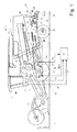
- FIG. 1 shows a side view of an agricultural machine designed as a combine harvester 1 during harvesting.
- the crop 2 is first picked up by a cutting unit 3, which feeds the crop 2 to an inclined conveyor 4, which is arranged on the front of the combine harvester 1.
- an inclined conveyor 4 transfers the crop 2 to a threshing mechanism 6 arranged in the machine housing 5 of the combine harvester 1.
- the threshing unit 6 processes the crop 2 intensively, so that the grains are released from the crops of the crop 2
- a grain consisting predominantly of grains Chaff mixture 7 is deposited on the threshing and separating basket 8 of the threshing 6 and passes through a preparation tray 9 to a known and therefore not further explained here cleaning device 10, in which the grains of the non-grain constituents, ie of straw and Spreader parts are separated.
- Overflowing over the cleaning device 10 consisting essentially of short straw and chaff screen overflow 11 passes through a Zunaturalgeber 12 in an even closer to described Strohzerklein ceremoniess- and Vertert sensory 15, which includes at least one below a Strohausfallhaube 14 arranged straw chopper 13 and a downstream distribution device 31.
- the separator 18 In the rear region of the threshing 6 is associated with a rotating counterclockwise turning drum 16, which assumes the emerging from the threshing 6, consisting essentially of threshed crops Gutstrom 17 and a separator 18 such as two juxtaposed separating rotors 19 feeds the goods 17
- the separator 18 In the rear region of the combine harvester 1 promote the still in the flow 17 grains 20 and possibly short straw 21 and chaff 22 are separated by falling through the screen openings provided with separation rotors 19 through a return bottom 23, the separator 18 is not on this Restricted execution, the separator 18 may also be designed as a known and therefore not shown Horden commonlyler, but it is also conceivable that the separator 18 is designed as a single rotor or double rotor system in which each rotor a so-called threshing un d deposition area has.
- the return bottom 23 transports grains 21, short straw 20 and chaff 22 also to the preparation tray 9 and via this likewise into the cleaning device 10, in which the grains 21 are separated from the short straw 20 and from the chaff 22
- the crop material 24 emerging from the separating rotors 19 at the end of the separating rotors 19 and for the most part consisting of straw is fed to the straw chopper 13 via the straw chute hood 14.
- the straw chopper 13 has a rotary cutter shaft 26 which is mounted in the chopper housing 27.
- the chopper shaft 26 is occupied with movable blades 28 which mesh with fixed in the chopper housing 27 counter knives 29.
- the crop 24 is shredded to shredded material 30 and accelerated and fed at high speed to a arranged on the machine housing 5 distribution device 31, with which the shredded material 30 is distributed on the field floor 32.
- the distributing device 31 are subordinate to later explained inventive guide elements 33, 34, with which the emerging from the distributor 31 shred 30 experiences in a manner to be described in more detail, at least in the vertical direction, a change in Gutaustrittraum.
- the combine harvester 1 is designed as a so-called slope combine harvester, the front axle 36 receives a known slope compensation system 37, wherein the two wheels 38 of the front axle 36 associated with such a leveling system 37
- Each slope compensation system 37 is substantially of a with the respective impeller 38 in Active connection standing wheel gear 39 is formed, soft about the front axle 36 is pivotally mounted on this.
- the pivoting of the wheel gear 39 is achieved in that between the brackets 40 of the front axle 36 and the wheel gears 39 each have a lifting cylinder 41 is arranged, the pressurization or pressure relief leads to a pivoting of the associated wheel gear 39 clockwise or counterclockwise about the front axle 36.
- the wheel gear 39 are pivoted in the manner described about the front axle 36, at the same time change the connected to the wheel gear 39 wheels 38 their position on the combine 1 in both the vertical and in the horizontal direction, whereby the machine housing 5 can be aligned.
- the combine harvester 1 shown has different sensors at different points in a manner to be described in more detail. These include first so-called tilt sensors 43, 44 which are fixedly connected to the machine housing 5. The tilt sensors 43, 44 detect the longitudinal and transverse inclination of the machine frame 5 and the field bottom 32 and generate depending on this longitudinal or transverse inclination signals H, l.
- the slope compensation systems 37 of the combine harvester 1 are further associated with rotational angle sensors 45, which determine the pivot angle 41 of the wheel gear 39 relative to the front axle 36 and thus the position of the wheels 38 to the machine housing 5.
- the rotation angle sensors 45 generate inclination signals K, L proportional to the position of the wheel gear 34 relative to the front axle 36
- the inclination sensors 43, 44 and the rotation angle sensors 45 are connected to a control and evaluation unit 47.
- the control and evaluation unit 47 determines control signals M, N as a function of the inclination signals H, l generated by the inclination sensors 43, 44 and depending on the inclination signals K, L generated by the rotation angle sensors 45.
- the control signals M, N control the pressurization or respectively Pressure relief of the lifting cylinder 41 of the slope compensation systems 37, each slope compensation system 37 is controlled separately, so that each impeller 38 can be adjusted individually to the bottom profile of the field bottom 32.
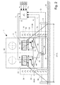
- FIG. 2 shows the rear view of the combine harvester 1 illustrated in FIG. 1 during harvesting on a horizontal field floor 32.
- the distributing device 31 consists of two side-by-side blowers 49, 50 arranged on the machine housing 5, behind which the shredded material 30 emerging on trajectories lies behind on a spreading width 51 the Dispose combine harvester 1 on the field floor 32, wherein the distribution width 51 in the illustrated embodiment advantageously corresponds to the working width 52 of the cutting unit 3 of the combine 1 and both the working width 51 and the distribution width 52 are arranged symmetrically to the central axis 53 of the combine 1, to simplify 2, only the outer trajectories 69, 70 of the shredded material 30 are shown.
- the trailing fans 49, 50 according to the invention guide elements 33, 34 are each arranged about an approximately perpendicular to the central axis 53 of the combine harvester 1 axis 54, 55 pivotally mounted on the machine housing 5, wherein between the machine housing 5 and an associated guide element 33, 34 rigidly arranged levers 56, 57 each have an actuator 58, 59 is articulated, with which the respective guide element 33, 34 can be pivoted.
- the actuators 58, 59 are designed as linear motors 60, 61 in the illustrated embodiment. However, it is also conceivable to perform the actuators 58, 59 as a hydraulic cylinder.
- the guide elements 33, 34 are arranged below the throwing fans 49, 50, so that the chopped material 30 emerging radially from the throwing blowers 49, 50 is not deflected by the guide elements 33, 44.
- the instantaneous positions of the guide elements 33, 34 are respectively detected via the linear motors 60, 61 associated displacement sensors 64, 65 proportional to the current displacement of the linear motors 61, 62 generate position signals P, R.
- the machine housing 5 is mounted in the rear area of the combine harvester 1 on a swinging rear axle 66 which adapts to the inclination of the field floor 32.
- the oscillating rear axle 66 of the combine harvester 1 is assigned a rotational angle sensor 67, which detects the instantaneous position of the rear axle 66 relative to the machine housing 5 and generates a tilt signal Q depending on the position.
- the oscillating rear axle 66 may also be associated with an inclination sensor, with which the inclination of the field bottom 32 can be determined.
- the displacement sensors 64, 65 on the linear motors 61, 62 and the rotation angle sensor 67 on the oscillating rear axle 66 are also connected to the control and evaluation unit 47 and pass to this the tilt signal Q generated by the rotation angle sensor 67 and those generated by the travel sensors 64, 65 Position signals P, R. While the tilt signals H generated by the tilt sensors 43, 44 fixed to the machine frame 5 are used to define the control signals M, N for the lift cylinders 41 of the slope compensation systems 37, the tilt signals K generated by the various rotation angle sensors 45, 67 are used , L, Q first to determine the deflection of the wheels 38 of the front axle 36 and the deflection of the oscillating mounted rear axle 66.
- tilt signals K, L, Q as described in more detail below, also used to generate control signals S, T, the a retraction or extension of the respective linear motors 60, 61 cause such d the guide plates 33, 34 according to the invention are pivoted in dependence on the inclination of the field bottom 32.
- the invention will now be described in detail.
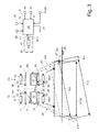
- the combine harvester 1 would be aligned almost horizontal to the ground 32, the throwing fans 49, 50 are also aligned horizontally because of their rigid articulation on the combine 1.
- the throwing fans 49, 50 have the distribution characteristic in a manner known per se that the shredded material 30 passing through the throwing fans 49, 50 is deposited on the floor 32 over a spreading width 51 which corresponds to the working width 52 of the cutting unit 3. If the combine harvester 1 now passes over a floor 32a which has a marked slope, the slope compensation system 37 already described would move the combine harvester 1 and the discharge fans 49, 50 connected to it again to a horizontal position.
- the distribution width 51a realized by the throwing blowers 49, 50 changes in such a way that the throwing distance shortens uphill while the throwing distance increases downhill. This is where the invention begins.
- the distribution width 51a and the working width 52a to end up in a similar range at least upstream of the hatch, the product flow 30 emerging from the throwing fans 49, 50 must be deflected more uphill.
- control and evaluation unit 47 would cause the adjustment of the actuators 75, 76 in such a way that the guide element 71, 72 respectively disposed downstream is pivoted about its pivot axis 77, 78 in the direction of the bottom 32a, so that the fury blower 49th As a result, this also means that in the downhill region the vertical width 51a and the working width 52a almost coincide,
- the control and evaluation unit 47 at least from the rotational angle sensor 67 associated with the oscillating rear axle 66 and / or the inclination signals K generated by the tilt compensation system 37 L, Q generates at least one control signal S. T.
- the adjustment of the guide elements 33, 34, 71, 72 by retraction or extension of the coupling rods of the actuators 58, 59, 75, 76, so that the guide elements 33, 34, 71, 72 about their jewellige pivot axis 54, 55, 77, 78 are pivoted, wherein the respective mountain side and bottom side guide element 33, 34 is pivoted about its pivot axis 54, 55 in the vertical direction upwards, while the valley side and top side guide element 71, 72 about its pivot axis 77, 78 in the vertical direction is swung down.
- the inclination sensors 43, 44 fixed to the machine housing 5 and the various rotation angle sensors 45, 67 are connected to the control and evaluation unit 47 and the control and evaluation unit 47 the inclination signals H generated by the inclination sensors 43, 44 l and the inclination signals K, L, Q generated by the rotation angle sensors 45, 67 and the control signals M, N of the lifting cylinders 41 of the slope compensation system 37 for defining the control signals S, T with which the linear motors 61, 62, 75, 76 are retracted and extended
- the control and evaluation unit 47 takes into account only a part of the signals described above.
- the guide elements 33, 34, 71, 72 are additionally adjusted in dependence on the wind direction and wind strength.
Landscapes
- Life Sciences & Earth Sciences (AREA)
- Environmental Sciences (AREA)
- Harvester Elements (AREA)
- Threshing Machine Elements (AREA)
- Outside Dividers And Delivering Mechanisms For Harvesters (AREA)
Applications Claiming Priority (1)
| Application Number | Priority Date | Filing Date | Title |
|---|---|---|---|
| DE200610026041 DE102006026041A1 (de) | 2006-06-01 | 2006-06-01 | Verteilvorrichtung zum Verteilen von aus einer Erntemaschine austretendem Erntegut |
Publications (3)
| Publication Number | Publication Date |
|---|---|
| EP1862055A2 true EP1862055A2 (fr) | 2007-12-05 |
| EP1862055A3 EP1862055A3 (fr) | 2008-09-03 |
| EP1862055B1 EP1862055B1 (fr) | 2017-05-10 |
Family
ID=38474065
Family Applications (1)
| Application Number | Title | Priority Date | Filing Date |
|---|---|---|---|
| EP07103435.9A Active EP1862055B1 (fr) | 2006-06-01 | 2007-03-02 | Dispositif de répartition destiné à la répartition d'épinards sortant d'une hacheuse |
Country Status (2)
| Country | Link |
|---|---|
| EP (1) | EP1862055B1 (fr) |
| DE (1) | DE102006026041A1 (fr) |
Cited By (5)
| Publication number | Priority date | Publication date | Assignee | Title |
|---|---|---|---|---|
| EP2769613A1 (fr) * | 2013-02-22 | 2014-08-27 | CLAAS Saulgau GmbH | Dispositif de commande pour le fonctionnement d'une moissonneuse et moissonneuse dotée d'un tel dispositif de commande |
| WO2018162680A1 (fr) * | 2017-03-09 | 2018-09-13 | Cnh Industrial Belgium Nv | Système d'épandeur pour une moissonneuse agricole avec déflecteur oscillant |
| EP3476202A1 (fr) * | 2017-10-30 | 2019-05-01 | Deere & Company | Procédé de commande de niveau pour une moissonneuse-batteuse agricole |
| US20220394925A1 (en) * | 2021-06-09 | 2022-12-15 | Cnh Industrial America Llc | Combine harvester with tilted crop material sensor arrangement |
| CN119452888A (zh) * | 2024-12-16 | 2025-02-18 | 四川农业大学 | 一种可自适应调节的玉米剥皮装置 |
Families Citing this family (8)
| Publication number | Priority date | Publication date | Assignee | Title |
|---|---|---|---|---|
| DE102016118187A1 (de) | 2016-09-27 | 2018-03-29 | Claas Selbstfahrende Erntemaschinen Gmbh | Mähdrescher mit Fahrerassistenzsystem |
| BR102019009913A2 (pt) | 2018-05-17 | 2020-05-05 | Cnh Ind America Llc | descarga de resíduo a partir de uma ceifeira-debulhadora |
| USD1031792S1 (en) | 2022-08-30 | 2024-06-18 | Calmer Holding Company, Llc | Round bar concave |
| USD1031791S1 (en) | 2022-08-30 | 2024-06-18 | Calmer Holding Company, Llc | Straight bar concave |
| USD1031793S1 (en) | 2022-08-30 | 2024-06-18 | Calmer Holding Company, Llc | Separating grate |
| USD1032666S1 (en) | 2022-08-30 | 2024-06-25 | Calmer Holding Company, Llc | MOG limiting subassembly for combine concave |
| US11877538B1 (en) | 2022-08-30 | 2024-01-23 | Calmer Holding Company, Llc | Threshing grains and legumes utilizing concaves with adjustable openings |
| USD1058613S1 (en) | 2022-11-29 | 2025-01-21 | Calmer Holding Company, Llc | Limiter plates |
Family Cites Families (9)
| Publication number | Priority date | Publication date | Assignee | Title |
|---|---|---|---|---|
| DE3438609A1 (de) * | 1984-10-20 | 1986-04-24 | Claas Ohg, 4834 Harsewinkel | Maehdrescher mit anbauhaecksler |
| FR2651957A1 (en) * | 1989-09-21 | 1991-03-22 | Cemagref | Method and device for correcting the drift of an agricultural implement |
| DE4134136A1 (de) * | 1991-10-16 | 1993-04-22 | Deere & Co | Verteilvorrichtung |
| DE4419421C2 (de) * | 1994-06-03 | 1996-03-28 | Claas Ohg | Verteilvorrichtung für Häcksler |
| DE19823347A1 (de) * | 1998-05-13 | 1999-11-18 | Claas Ohg | Einrichtung zur Steuerung und Einstellung von Arbeitszylindern |
| US6602131B2 (en) * | 2001-12-12 | 2003-08-05 | Case Corporation | Multi-tier crop residue flow guide for an agricultural combine |
| ES2257130B1 (es) * | 2003-10-08 | 2007-07-16 | Angel Carlos Irujo Lopez | Sistema nivelador-compensador para maquinas cosechadoras y similares. |
| CA2465142C (fr) * | 2004-04-23 | 2009-06-02 | Redekop Chaff Systems Ltd. | Moissonneuse-batteuse avec dispositif de projection muni d'une commande independante de largeur d'etalement |
| US7261633B2 (en) * | 2005-02-15 | 2007-08-28 | Cnh America Llc | Unitary pivoting spreader apparatus |
-
2006
- 2006-06-01 DE DE200610026041 patent/DE102006026041A1/de not_active Withdrawn
-
2007
- 2007-03-02 EP EP07103435.9A patent/EP1862055B1/fr active Active
Cited By (9)
| Publication number | Priority date | Publication date | Assignee | Title |
|---|---|---|---|---|
| EP2769613A1 (fr) * | 2013-02-22 | 2014-08-27 | CLAAS Saulgau GmbH | Dispositif de commande pour le fonctionnement d'une moissonneuse et moissonneuse dotée d'un tel dispositif de commande |
| WO2018162680A1 (fr) * | 2017-03-09 | 2018-09-13 | Cnh Industrial Belgium Nv | Système d'épandeur pour une moissonneuse agricole avec déflecteur oscillant |
| BE1025043B1 (nl) * | 2017-03-09 | 2018-10-11 | Cnh Industrial Belgium Nv | Strooisysteem voor een oogstmachine voor landbouwtoepassingen met een heen- en weergaande deflector |
| US11547048B2 (en) | 2017-03-09 | 2023-01-10 | Cnh Industrial America Llc | Spreader system for an agricultural harvester with an oscillating deflector |
| EP3476202A1 (fr) * | 2017-10-30 | 2019-05-01 | Deere & Company | Procédé de commande de niveau pour une moissonneuse-batteuse agricole |
| US10375890B2 (en) | 2017-10-30 | 2019-08-13 | Deere & Company | Level control method for an agricultural combine |
| US20220394925A1 (en) * | 2021-06-09 | 2022-12-15 | Cnh Industrial America Llc | Combine harvester with tilted crop material sensor arrangement |
| US12457930B2 (en) * | 2021-06-09 | 2025-11-04 | Cnh Industrial America Llc | Combine harvester with tilted crop material sensor arrangement |
| CN119452888A (zh) * | 2024-12-16 | 2025-02-18 | 四川农业大学 | 一种可自适应调节的玉米剥皮装置 |
Also Published As
| Publication number | Publication date |
|---|---|
| DE102006026041A1 (de) | 2007-12-20 |
| EP1862055A3 (fr) | 2008-09-03 |
| EP1862055B1 (fr) | 2017-05-10 |
Similar Documents
| Publication | Publication Date | Title |
|---|---|---|
| EP1862055B1 (fr) | Dispositif de répartition destiné à la répartition d'épinards sortant d'une hacheuse | |
| EP2298061B1 (fr) | Procédé de répartition d'un flux de matière sur un champ et dispositif de hachage et de répartition | |
| EP3000303B1 (fr) | Moissonneuse-batteuse dote d'un systeme d'assistance du conducteur | |
| EP1219164B1 (fr) | Procédé et dispositif pour convoyer des récoltes dans une machine agricole | |
| EP3000302B1 (fr) | Moissonneuse-batteuse equipée d'un dispositif de distribution | |
| EP1493318B1 (fr) | Procédé de control d'un ensemble de battage pour moissonneuse-batteuse | |
| EP2364587B1 (fr) | Séparateur axial pour une moissonneuse-batteuse | |
| EP2810549B1 (fr) | Moissonneuse-batteuse | |
| EP1897430B1 (fr) | Dispositif de hachage et de répartition | |
| EP2225929B1 (fr) | Dispositif de distribution de paille pour moissonneuse-batteuse | |
| DE102007009587A1 (de) | Vorrichtung zur Einstellung der Position des Nachbeschleunigungsorgans in einer landwirtschaftlichen Erntemaschine | |
| EP2845461B1 (fr) | Agencement de mesure de perte dans une moissonneuse-batteuse | |
| EP4008171B1 (fr) | Procédé de fonctionnement d'une moissonneuse-batteuse | |
| DE102010003907A1 (de) | Erntegutrestehäcksel und -verteilanordnung für einen Mähdrescher | |
| EP2708107B1 (fr) | Moissonneuse-batteuse automotrice | |
| EP0727135B1 (fr) | Moissonneuse-batteuse | |
| DE102018102594A1 (de) | Mähdrescher | |
| EP1856966B1 (fr) | Procédé et dispositif destiné au fonctionnement d'un dispositif de broyage et de répartition d'épinards | |
| EP2232976B1 (fr) | Agencement de hachage et de répartition de résidus de produits de récolte pour une moissonneuse-batteuse | |
| DE102013019680A1 (de) | Abscheidevorrichtung eines Rotor-Mähdreschers | |
| EP1532858B1 (fr) | Procédé et dispositif pour le broyage et la distribution de produits de récolte | |
| EP2181578A2 (fr) | Moissonneuse-batteuse et procédé de récolte | |
| DE29822621U1 (de) | Spreuverteiler für Mähdrescher | |
| EP3069596B1 (fr) | Ensileuse | |
| DE102015212608B4 (de) | Erntegutresteverteileinrichtung für einen Mähdrescher |
Legal Events
| Date | Code | Title | Description |
|---|---|---|---|
| PUAI | Public reference made under article 153(3) epc to a published international application that has entered the european phase |
Free format text: ORIGINAL CODE: 0009012 |
|
| AK | Designated contracting states |
Kind code of ref document: A2 Designated state(s): AT BE BG CH CY CZ DE DK EE ES FI FR GB GR HU IE IS IT LI LT LU LV MC MT NL PL PT RO SE SI SK TR |
|
| AX | Request for extension of the european patent |
Extension state: AL BA HR MK YU |
|
| PUAL | Search report despatched |
Free format text: ORIGINAL CODE: 0009013 |
|
| AK | Designated contracting states |
Kind code of ref document: A3 Designated state(s): AT BE BG CH CY CZ DE DK EE ES FI FR GB GR HU IE IS IT LI LT LU LV MC MT NL PL PT RO SE SI SK TR |
|
| AX | Request for extension of the european patent |
Extension state: AL BA HR MK RS |
|
| RIC1 | Information provided on ipc code assigned before grant |
Ipc: A01D 41/12 20060101AFI20070918BHEP Ipc: A01D 75/28 20060101ALI20080728BHEP |
|
| 17P | Request for examination filed |
Effective date: 20090303 |
|
| 17Q | First examination report despatched |
Effective date: 20090406 |
|
| AKX | Designation fees paid |
Designated state(s): AT BE BG CH CY CZ DE DK EE ES FI FR GB GR HU IE IS IT LI LT LU LV MC MT NL PL PT RO SE SI SK TR |
|
| RAP1 | Party data changed (applicant data changed or rights of an application transferred) |
Owner name: CLAAS SELBSTFAHRENDE ERNTEMASCHINEN GMBH |
|
| GRAP | Despatch of communication of intention to grant a patent |
Free format text: ORIGINAL CODE: EPIDOSNIGR1 |
|
| INTG | Intention to grant announced |
Effective date: 20161209 |
|
| GRAS | Grant fee paid |
Free format text: ORIGINAL CODE: EPIDOSNIGR3 |
|
| GRAA | (expected) grant |
Free format text: ORIGINAL CODE: 0009210 |
|
| AK | Designated contracting states |
Kind code of ref document: B1 Designated state(s): AT BE BG CH CY CZ DE DK EE ES FI FR GB GR HU IE IS IT LI LT LU LV MC MT NL PL PT RO SE SI SK TR |
|
| REG | Reference to a national code |
Ref country code: GB Ref legal event code: FG4D Free format text: NOT ENGLISH |
|
| REG | Reference to a national code |
Ref country code: AT Ref legal event code: REF Ref document number: 891305 Country of ref document: AT Kind code of ref document: T Effective date: 20170515 Ref country code: CH Ref legal event code: EP |
|
| REG | Reference to a national code |
Ref country code: IE Ref legal event code: FG4D Free format text: LANGUAGE OF EP DOCUMENT: GERMAN |
|
| REG | Reference to a national code |
Ref country code: DE Ref legal event code: R096 Ref document number: 502007015628 Country of ref document: DE |
|
| REG | Reference to a national code |
Ref country code: NL Ref legal event code: MP Effective date: 20170510 |
|
| REG | Reference to a national code |
Ref country code: LT Ref legal event code: MG4D |
|
| PG25 | Lapsed in a contracting state [announced via postgrant information from national office to epo] |
Ref country code: FI Free format text: LAPSE BECAUSE OF FAILURE TO SUBMIT A TRANSLATION OF THE DESCRIPTION OR TO PAY THE FEE WITHIN THE PRESCRIBED TIME-LIMIT Effective date: 20170510 Ref country code: GR Free format text: LAPSE BECAUSE OF FAILURE TO SUBMIT A TRANSLATION OF THE DESCRIPTION OR TO PAY THE FEE WITHIN THE PRESCRIBED TIME-LIMIT Effective date: 20170811 Ref country code: LT Free format text: LAPSE BECAUSE OF FAILURE TO SUBMIT A TRANSLATION OF THE DESCRIPTION OR TO PAY THE FEE WITHIN THE PRESCRIBED TIME-LIMIT Effective date: 20170510 Ref country code: ES Free format text: LAPSE BECAUSE OF FAILURE TO SUBMIT A TRANSLATION OF THE DESCRIPTION OR TO PAY THE FEE WITHIN THE PRESCRIBED TIME-LIMIT Effective date: 20170510 |
|
| PG25 | Lapsed in a contracting state [announced via postgrant information from national office to epo] |
Ref country code: SE Free format text: LAPSE BECAUSE OF FAILURE TO SUBMIT A TRANSLATION OF THE DESCRIPTION OR TO PAY THE FEE WITHIN THE PRESCRIBED TIME-LIMIT Effective date: 20170510 Ref country code: NL Free format text: LAPSE BECAUSE OF FAILURE TO SUBMIT A TRANSLATION OF THE DESCRIPTION OR TO PAY THE FEE WITHIN THE PRESCRIBED TIME-LIMIT Effective date: 20170510 Ref country code: LV Free format text: LAPSE BECAUSE OF FAILURE TO SUBMIT A TRANSLATION OF THE DESCRIPTION OR TO PAY THE FEE WITHIN THE PRESCRIBED TIME-LIMIT Effective date: 20170510 Ref country code: IS Free format text: LAPSE BECAUSE OF FAILURE TO SUBMIT A TRANSLATION OF THE DESCRIPTION OR TO PAY THE FEE WITHIN THE PRESCRIBED TIME-LIMIT Effective date: 20170910 Ref country code: BG Free format text: LAPSE BECAUSE OF FAILURE TO SUBMIT A TRANSLATION OF THE DESCRIPTION OR TO PAY THE FEE WITHIN THE PRESCRIBED TIME-LIMIT Effective date: 20170810 Ref country code: PL Free format text: LAPSE BECAUSE OF FAILURE TO SUBMIT A TRANSLATION OF THE DESCRIPTION OR TO PAY THE FEE WITHIN THE PRESCRIBED TIME-LIMIT Effective date: 20170510 |
|
| PG25 | Lapsed in a contracting state [announced via postgrant information from national office to epo] |
Ref country code: DK Free format text: LAPSE BECAUSE OF FAILURE TO SUBMIT A TRANSLATION OF THE DESCRIPTION OR TO PAY THE FEE WITHIN THE PRESCRIBED TIME-LIMIT Effective date: 20170510 Ref country code: RO Free format text: LAPSE BECAUSE OF FAILURE TO SUBMIT A TRANSLATION OF THE DESCRIPTION OR TO PAY THE FEE WITHIN THE PRESCRIBED TIME-LIMIT Effective date: 20170510 Ref country code: CZ Free format text: LAPSE BECAUSE OF FAILURE TO SUBMIT A TRANSLATION OF THE DESCRIPTION OR TO PAY THE FEE WITHIN THE PRESCRIBED TIME-LIMIT Effective date: 20170510 Ref country code: SK Free format text: LAPSE BECAUSE OF FAILURE TO SUBMIT A TRANSLATION OF THE DESCRIPTION OR TO PAY THE FEE WITHIN THE PRESCRIBED TIME-LIMIT Effective date: 20170510 Ref country code: EE Free format text: LAPSE BECAUSE OF FAILURE TO SUBMIT A TRANSLATION OF THE DESCRIPTION OR TO PAY THE FEE WITHIN THE PRESCRIBED TIME-LIMIT Effective date: 20170510 |
|
| REG | Reference to a national code |
Ref country code: DE Ref legal event code: R097 Ref document number: 502007015628 Country of ref document: DE |
|
| PLBE | No opposition filed within time limit |
Free format text: ORIGINAL CODE: 0009261 |
|
| STAA | Information on the status of an ep patent application or granted ep patent |
Free format text: STATUS: NO OPPOSITION FILED WITHIN TIME LIMIT |
|
| REG | Reference to a national code |
Ref country code: FR Ref legal event code: PLFP Year of fee payment: 12 |
|
| 26N | No opposition filed |
Effective date: 20180213 |
|
| PG25 | Lapsed in a contracting state [announced via postgrant information from national office to epo] |
Ref country code: SI Free format text: LAPSE BECAUSE OF FAILURE TO SUBMIT A TRANSLATION OF THE DESCRIPTION OR TO PAY THE FEE WITHIN THE PRESCRIBED TIME-LIMIT Effective date: 20170510 |
|
| PG25 | Lapsed in a contracting state [announced via postgrant information from national office to epo] |
Ref country code: MT Free format text: LAPSE BECAUSE OF FAILURE TO SUBMIT A TRANSLATION OF THE DESCRIPTION OR TO PAY THE FEE WITHIN THE PRESCRIBED TIME-LIMIT Effective date: 20170510 |
|
| REG | Reference to a national code |
Ref country code: CH Ref legal event code: PL |
|
| GBPC | Gb: european patent ceased through non-payment of renewal fee |
Effective date: 20180302 |
|
| PG25 | Lapsed in a contracting state [announced via postgrant information from national office to epo] |
Ref country code: MC Free format text: LAPSE BECAUSE OF FAILURE TO SUBMIT A TRANSLATION OF THE DESCRIPTION OR TO PAY THE FEE WITHIN THE PRESCRIBED TIME-LIMIT Effective date: 20170510 |
|
| REG | Reference to a national code |
Ref country code: IE Ref legal event code: MM4A |
|
| PG25 | Lapsed in a contracting state [announced via postgrant information from national office to epo] |
Ref country code: LU Free format text: LAPSE BECAUSE OF NON-PAYMENT OF DUE FEES Effective date: 20180302 |
|
| PG25 | Lapsed in a contracting state [announced via postgrant information from national office to epo] |
Ref country code: IE Free format text: LAPSE BECAUSE OF NON-PAYMENT OF DUE FEES Effective date: 20180302 |
|
| PG25 | Lapsed in a contracting state [announced via postgrant information from national office to epo] |
Ref country code: LI Free format text: LAPSE BECAUSE OF NON-PAYMENT OF DUE FEES Effective date: 20180331 Ref country code: GB Free format text: LAPSE BECAUSE OF NON-PAYMENT OF DUE FEES Effective date: 20180302 Ref country code: CH Free format text: LAPSE BECAUSE OF NON-PAYMENT OF DUE FEES Effective date: 20180331 |
|
| REG | Reference to a national code |
Ref country code: AT Ref legal event code: MM01 Ref document number: 891305 Country of ref document: AT Kind code of ref document: T Effective date: 20180302 |
|
| PG25 | Lapsed in a contracting state [announced via postgrant information from national office to epo] |
Ref country code: AT Free format text: LAPSE BECAUSE OF NON-PAYMENT OF DUE FEES Effective date: 20180302 |
|
| PG25 | Lapsed in a contracting state [announced via postgrant information from national office to epo] |
Ref country code: TR Free format text: LAPSE BECAUSE OF FAILURE TO SUBMIT A TRANSLATION OF THE DESCRIPTION OR TO PAY THE FEE WITHIN THE PRESCRIBED TIME-LIMIT Effective date: 20170510 |
|
| PGFP | Annual fee paid to national office [announced via postgrant information from national office to epo] |
Ref country code: DE Payment date: 20200130 Year of fee payment: 14 |
|
| PG25 | Lapsed in a contracting state [announced via postgrant information from national office to epo] |
Ref country code: PT Free format text: LAPSE BECAUSE OF FAILURE TO SUBMIT A TRANSLATION OF THE DESCRIPTION OR TO PAY THE FEE WITHIN THE PRESCRIBED TIME-LIMIT Effective date: 20170510 Ref country code: HU Free format text: LAPSE BECAUSE OF FAILURE TO SUBMIT A TRANSLATION OF THE DESCRIPTION OR TO PAY THE FEE WITHIN THE PRESCRIBED TIME-LIMIT; INVALID AB INITIO Effective date: 20070302 |
|
| PG25 | Lapsed in a contracting state [announced via postgrant information from national office to epo] |
Ref country code: CY Free format text: LAPSE BECAUSE OF FAILURE TO SUBMIT A TRANSLATION OF THE DESCRIPTION OR TO PAY THE FEE WITHIN THE PRESCRIBED TIME-LIMIT Effective date: 20170510 |
|
| PGFP | Annual fee paid to national office [announced via postgrant information from national office to epo] |
Ref country code: IT Payment date: 20200318 Year of fee payment: 14 |
|
| REG | Reference to a national code |
Ref country code: DE Ref legal event code: R119 Ref document number: 502007015628 Country of ref document: DE |
|
| PG25 | Lapsed in a contracting state [announced via postgrant information from national office to epo] |
Ref country code: DE Free format text: LAPSE BECAUSE OF NON-PAYMENT OF DUE FEES Effective date: 20211001 |
|
| PG25 | Lapsed in a contracting state [announced via postgrant information from national office to epo] |
Ref country code: IT Free format text: LAPSE BECAUSE OF NON-PAYMENT OF DUE FEES Effective date: 20210302 |
|
| P01 | Opt-out of the competence of the unified patent court (upc) registered |
Effective date: 20230515 |
|
| PGFP | Annual fee paid to national office [announced via postgrant information from national office to epo] |
Ref country code: BE Payment date: 20260319 Year of fee payment: 20 |
|
| PGFP | Annual fee paid to national office [announced via postgrant information from national office to epo] |
Ref country code: FR Payment date: 20260320 Year of fee payment: 20 |