EP1862214A2 - Procédé et dispositif destinés à relier des fibres dans la zone d'un tube de soufflage - Google Patents
Procédé et dispositif destinés à relier des fibres dans la zone d'un tube de soufflage Download PDFInfo
- Publication number
- EP1862214A2 EP1862214A2 EP07010867A EP07010867A EP1862214A2 EP 1862214 A2 EP1862214 A2 EP 1862214A2 EP 07010867 A EP07010867 A EP 07010867A EP 07010867 A EP07010867 A EP 07010867A EP 1862214 A2 EP1862214 A2 EP 1862214A2
- Authority
- EP
- European Patent Office
- Prior art keywords
- fibers
- component
- binder
- constriction
- nozzle
- Prior art date
- Legal status (The legal status is an assumption and is not a legal conclusion. Google has not performed a legal analysis and makes no representation as to the accuracy of the status listed.)
- Withdrawn
Links
- 238000000034 method Methods 0.000 title claims description 26
- 239000000835 fiber Substances 0.000 claims abstract description 126
- 239000000725 suspension Substances 0.000 claims abstract description 23
- XLYOFNOQVPJJNP-UHFFFAOYSA-N water Substances O XLYOFNOQVPJJNP-UHFFFAOYSA-N 0.000 claims abstract description 19
- 238000004519 manufacturing process Methods 0.000 claims abstract description 13
- 239000011230 binding agent Substances 0.000 claims description 92
- 238000004026 adhesive bonding Methods 0.000 claims description 26
- 238000005507 spraying Methods 0.000 claims description 7
- 238000007664 blowing Methods 0.000 claims description 3
- 238000000465 moulding Methods 0.000 claims description 3
- 238000007599 discharging Methods 0.000 claims description 2
- 239000012530 fluid Substances 0.000 claims description 2
- 238000004544 sputter deposition Methods 0.000 claims 2
- 239000000203 mixture Substances 0.000 claims 1
- 238000000889 atomisation Methods 0.000 abstract description 15
- 239000011094 fiberboard Substances 0.000 abstract description 12
- 239000007767 bonding agent Substances 0.000 abstract 7
- 239000011248 coating agent Substances 0.000 abstract 3
- 238000000576 coating method Methods 0.000 abstract 3
- 230000003116 impacting effect Effects 0.000 abstract 1
- 238000002156 mixing Methods 0.000 description 16
- UFHFLCQGNIYNRP-UHFFFAOYSA-N Hydrogen Chemical compound [H][H] UFHFLCQGNIYNRP-UHFFFAOYSA-N 0.000 description 4
- 229910052739 hydrogen Inorganic materials 0.000 description 4
- 239000001257 hydrogen Substances 0.000 description 4
- 238000009826 distribution Methods 0.000 description 3
- 239000003292 glue Substances 0.000 description 3
- 241000294754 Macroptilium atropurpureum Species 0.000 description 2
- 230000001419 dependent effect Effects 0.000 description 2
- 230000029087 digestion Effects 0.000 description 2
- 230000000694 effects Effects 0.000 description 2
- 230000002349 favourable effect Effects 0.000 description 2
- 239000002245 particle Substances 0.000 description 2
- 238000012546 transfer Methods 0.000 description 2
- 230000001133 acceleration Effects 0.000 description 1
- 238000013459 approach Methods 0.000 description 1
- 230000015572 biosynthetic process Effects 0.000 description 1
- 238000007796 conventional method Methods 0.000 description 1
- 238000011161 development Methods 0.000 description 1
- 230000018109 developmental process Effects 0.000 description 1
- 238000001704 evaporation Methods 0.000 description 1
- 230000008020 evaporation Effects 0.000 description 1
- 238000007731 hot pressing Methods 0.000 description 1
- 238000011835 investigation Methods 0.000 description 1
- 239000000463 material Substances 0.000 description 1
- 239000011236 particulate material Substances 0.000 description 1
- 238000000926 separation method Methods 0.000 description 1
- 238000004513 sizing Methods 0.000 description 1
- 239000002904 solvent Substances 0.000 description 1
- 239000007921 spray Substances 0.000 description 1
- 239000007858 starting material Substances 0.000 description 1
- 238000009827 uniform distribution Methods 0.000 description 1
- 238000011144 upstream manufacturing Methods 0.000 description 1
Images

Classifications
-
- B—PERFORMING OPERATIONS; TRANSPORTING
- B27—WORKING OR PRESERVING WOOD OR SIMILAR MATERIAL; NAILING OR STAPLING MACHINES IN GENERAL
- B27N—MANUFACTURE BY DRY PROCESSES OF ARTICLES, WITH OR WITHOUT ORGANIC BINDING AGENTS, MADE FROM PARTICLES OR FIBRES CONSISTING OF WOOD OR OTHER LIGNOCELLULOSIC OR LIKE ORGANIC MATERIAL
- B27N1/00—Pretreatment of moulding material
- B27N1/02—Mixing the material with binding agent
-
- B—PERFORMING OPERATIONS; TRANSPORTING
- B01—PHYSICAL OR CHEMICAL PROCESSES OR APPARATUS IN GENERAL
- B01F—MIXING, e.g. DISSOLVING, EMULSIFYING OR DISPERSING
- B01F25/00—Flow mixers; Mixers for falling materials, e.g. solid particles
- B01F25/30—Injector mixers
- B01F25/31—Injector mixers in conduits or tubes through which the main component flows
- B01F25/313—Injector mixers in conduits or tubes through which the main component flows wherein additional components are introduced in the centre of the conduit
- B01F25/3131—Injector mixers in conduits or tubes through which the main component flows wherein additional components are introduced in the centre of the conduit with additional mixing means other than injector mixers, e.g. screens, baffles or rotating elements
-
- B—PERFORMING OPERATIONS; TRANSPORTING
- B01—PHYSICAL OR CHEMICAL PROCESSES OR APPARATUS IN GENERAL
- B01F—MIXING, e.g. DISSOLVING, EMULSIFYING OR DISPERSING
- B01F25/00—Flow mixers; Mixers for falling materials, e.g. solid particles
- B01F25/40—Static mixers
- B01F25/42—Static mixers in which the mixing is affected by moving the components jointly in changing directions, e.g. in tubes provided with baffles or obstructions
- B01F25/43—Mixing tubes, e.g. wherein the material is moved in a radial or partly reversed direction
- B01F25/433—Mixing tubes wherein the shape of the tube influences the mixing, e.g. mixing tubes with varying cross-section or provided with inwardly extending profiles
-
- B—PERFORMING OPERATIONS; TRANSPORTING
- B01—PHYSICAL OR CHEMICAL PROCESSES OR APPARATUS IN GENERAL
- B01F—MIXING, e.g. DISSOLVING, EMULSIFYING OR DISPERSING
- B01F25/00—Flow mixers; Mixers for falling materials, e.g. solid particles
- B01F25/40—Static mixers
- B01F25/42—Static mixers in which the mixing is affected by moving the components jointly in changing directions, e.g. in tubes provided with baffles or obstructions
- B01F25/43—Mixing tubes, e.g. wherein the material is moved in a radial or partly reversed direction
- B01F25/433—Mixing tubes wherein the shape of the tube influences the mixing, e.g. mixing tubes with varying cross-section or provided with inwardly extending profiles
- B01F25/4335—Mixers with a converging-diverging cross-section
-
- B—PERFORMING OPERATIONS; TRANSPORTING
- B01—PHYSICAL OR CHEMICAL PROCESSES OR APPARATUS IN GENERAL
- B01F—MIXING, e.g. DISSOLVING, EMULSIFYING OR DISPERSING
- B01F25/00—Flow mixers; Mixers for falling materials, e.g. solid particles
- B01F2025/91—Direction of flow or arrangement of feed and discharge openings
- B01F2025/913—Vortex flow, i.e. flow spiraling in a tangential direction and moving in an axial direction
-
- B—PERFORMING OPERATIONS; TRANSPORTING
- B01—PHYSICAL OR CHEMICAL PROCESSES OR APPARATUS IN GENERAL
- B01F—MIXING, e.g. DISSOLVING, EMULSIFYING OR DISPERSING
- B01F23/00—Mixing according to the phases to be mixed, e.g. dispersing or emulsifying
- B01F23/20—Mixing gases with liquids
- B01F23/21—Mixing gases with liquids by introducing liquids into gaseous media
-
- B—PERFORMING OPERATIONS; TRANSPORTING
- B01—PHYSICAL OR CHEMICAL PROCESSES OR APPARATUS IN GENERAL
- B01F—MIXING, e.g. DISSOLVING, EMULSIFYING OR DISPERSING
- B01F23/00—Mixing according to the phases to be mixed, e.g. dispersing or emulsifying
- B01F23/50—Mixing liquids with solids
- B01F23/57—Mixing high-viscosity liquids with solids
Definitions
- the invention relates to a process for the gluing of fibers with at least one component of a binder for the production of moldings from the glued with the binder fibers, in particular fiberboard, with the features of the preamble of independent claim 1 and an apparatus for performing a Such method having the features of the preamble of independent claim 8.
- a critical issue in the production of molded articles from binder-bonded fibers is the sizing of the fibers, i. H. the application of the binder to the fibers because, especially with a large relative surface area of the fibers and a small amount of binder, which is cost-prohibitive, it is difficult to evenly distribute the relatively small amount of binder over the fibers.
- This problem is particularly evident in the production of medium-density fiberboard, i. so-called MDF boards, come to light.
- MDF boards medium-density fiberboard
- the gluing of the fibers took place in so-called tray mixers, but fiber agglomerates and caking occurred, which resulted in uneven fiber gluing. This was especially evident in an undesirable formation of glue spots on the surfaces of the finished fiberboard.
- the uneven Faserbeleimung does not occur when, as in a method having the features of the preamble of independent claim 1 or in a device with the features of the preamble of independent claim 8, the gluing of the fibers in the blowpipe takes place.
- the binder is sprayed onto the fibers, that is sprayed through a nozzle, while suspended in water vapor from a refiner through the blowpipe to a Dryer be led.
- the water vapor suspending the fibers is formed in the transfer of the fibers from the refiner, in which they were digested under the action of moisture and elevated pressure and temperature from a starting material, with partial relaxation of the increased pressure in the blowpipe are passed.
- the partial relaxation of the pressure leads, in addition to the desired separation of the fibers by way of a pressure disintegration, also to an evaporation of the moisture from the digestion to water vapor.
- the dryer following the blowpipe is used to adjust the fiber moisture to a desired residual dimension.
- the turbulence in the blowpipe and at the exit of the blower pipe discharging into the dryer provide a thorough mixing of the fibers which results in a sufficiently even distribution of the binder over the entirety of the fibers. In a Blasrohrbeleimung occur accordingly no glue spots on the fiberboard produced.
- a disadvantage of the known Blasrohrbeleimung is the increased consumption of binder, which is about 11 to 13% binder / atro fibers above the binder consumption of Trogmischerbeleimung of about 9 to 11%, if the same mechanical properties of the fiberboards produced are achieved.
- binder which is about 11 to 13% binder / atro fibers above the binder consumption of Trogmischerbeleimung of about 9 to 11%
- a method having the features of the preamble of independent claim 1 and an apparatus having the features of independent claim 8 are known in which a mixing work performed by the hydrogen suspension of the fibers flowing through statically arranged mixing tools is monitored and set to a minimum value becomes.
- This minimum amount of mixing work ensures minimum mixing of the fibers during or after the binder is applied to them.
- the binder consumption To reduce this, because the quality of the gluing and thus also the quality of the fiberboard depending on the gluing of the fibers is stabilized and it is therefore possible to dispense with binder surcharges to ensure a certain minimum quality over quality variations.
- a substantial reduction of the binder consumption is not achieved by basically maintaining the usual pressure curve over the blowpipe.
- an apparatus for continuously mixing relatively small amounts of a finely divided component with a carrier moved by an air flow is known. It is provided that the carrier moved by the air flow passes through a mixing tube to which a spraying device is assigned.
- the nozzles can be arranged on the axis of the mixing tube and aligned in the conveying direction through the mixing tube.
- the mixing tube may be formed narrowed in the region of the spray nozzle. Specifically, it is about the gluing of Spangut, wherein for generating the air flow through the support tube, a fan is provided.
- the Blasrohrbeleimung of fibers also deals with the DE 1 632 450 A Not.
- the invention has for its object to provide a method having the features of the preamble of independent claim 1 and an apparatus having the features of the preamble of independent claim 8, with which despite gluing the Fibers in the area of the blowpipe a significant savings in binder with constant quality of the molded body produced over known methods of gluing in the blowpipe is possible.
- the object of the invention is achieved by a method having the features of independent claim 1 and by an apparatus having the features of independent claim 8.
- Preferred embodiments of the new method are described in the dependent claims 2 to 7, while the dependent claims 9 to 13 relate to preferred embodiments of the new device.
- fibers can also be glued with the method according to the invention or the apparatus according to the invention in order to produce other shaped bodies by curing the binder from the glued fibers.
- the fibers suspended in the water vapor are passed through a nozzle-shaped constriction of the blow tube, wherein the component of the binder is sprayed onto the fibers in the region of the constriction on the axis of the blow tube in the main direction of movement of the fibers.
- the component of the binder is sprayed onto the fibers from behind as they pass through the throat of the blowpipe.
- the component of the binder Due to the fine atomization of the component of the binder coupled with the strong mixing of the atomized component of the binder with the fibers, the component of the binder is very finely and evenly distributed over the fibers. This very favorable fine distribution of the component of the binder makes it possible to significantly reduce the binder consumption without sacrificing the quality of the molded body produced compared to known methods for gluing the fibers in the blowpipe. It should be noted that a reduction of the binder consumption of only one percentage point binder / atro fibers, for example, in the production of medium-density fiberboard already means a very significant cost reduction.
- the nozzle-shaped constriction of the blower tube according to the invention can already be provided at the outlet of the refiner releasing the fibers under pressure release into the blowpipe and there even replace a possibly existing valve, which is referred to in the prior art as a blow valve.
- the nozzle-shaped constriction may also be provided at the other end of the blowpipe, d. H. at the entrance of the adjoining the blower dryer.
- the suspension of the fibers suspended in the steam together with the component of the binder is injected into the dryer.
- occurring at the entrance of the dryer pressure release of the steam suspension can be used for additional mixing of the component of the binder with the fibers.
- the gluing of the fibers with the component of the binder can also be done at any other point of the blowpipe and especially where in the course of the blow tube in conventional methods, the gluing of the fibers.
- the component of the binder viewed in the direction of movement of the fibers, is sprayed onto the fibers shortly after the narrowest point of the narrowing.
- the constriction of the blowpipe including a nozzle used for injecting the component of the binder, may be designed to result in the arrangement of a two-fluid nozzle with external mixing in which the hydrogen suspension of the fibers forms the conveying or atomizing medium from which the component of the binder is atomized.
- a very fine atomization of the component of the binder is achieved without an additional conveying or atomizing medium when the component is sprayed on is used on the fibers.
- a well-suited atomizing medium under suitable pressure is available in more than sufficient amount for the fine atomization of the component of the binder.
- the component of the binder may even be comparatively viscous. However, if required, it can also be adjusted with a suitable solvent to a viscosity which is favorable for carrying out the new process.
- the fine atomization of the component of the binder in the new method in very small drops can be supported by the fact that the component is vorzerstäubt in their Aufdüsen before hitting the steam suspension of the fibers.
- an atomization of the component of the binder by the nozzle used for its jetting is meant an atomization of the component of the binder by the nozzle used for its jetting.
- the binder may be a one-component binder such that the binder component moistened in the region of the throat of the blowpipe is the sole component of the binder.
- a multicomponent binder Its components can be jointly sprayed through a nozzle in the region of a constriction of the blowpipe on the fibers; a plurality of constrictions of the blowpipe may be provided to sequentially jet the components of the binder onto the fibers; or another component may also be applied to the fibers after the dryer following the blowpipe. This is especially true if a pre-reaction of the components of the binder before a hot pressing of the glued fibers to the desired moldings to be avoided. In this case, the further component of the binder is applied as late as possible in front of a hot press used for this purpose on the fibers.
- a pressure ratio across the throat of the blowpipe can be adjusted within the typical range of> 1 to 4 in the new method.
- the pressure ratio is the quotient of the pressure in the blowpipe before the constriction and the pressure in the blowpipe after the use. Even beyond 4 going pressure conditions are basically conceivable, but difficult to achieve in the blowpipe existing systems and not required for the success of the new process.
- the constriction of the blowpipe by the nozzle used for spraying the component of the binder is to be taken into account in the pressure ratio which arises over the constriction of the blowpipe.
- the cross section of the blowpipe can be constant even over the constriction, wherein the free cross section in the region of the constriction is temporarily narrowed exclusively through the nozzle for atomizing the binder.
- the device according to the invention comprises a nozzle-shaped constriction of the blower tube, through which the fibers suspended in the steam pass, wherein the nozzle for spraying the component of the binder is arranged in the region of the constriction on the axis of the blowpipe that they the component of the binder in the main direction of movement of the fibers aufdüst on the fibers.
- the preferred embodiments of the device according to the invention essentially correspond to those of the method according to the invention.
- the position of the nozzle for spraying the component of the binder to the position of a constriction of the blowpipe in the direction of the axis of the blowpipe is adjustable.
- the effective constriction of the blower tube changes and, on the other hand, the location of the meeting of the component of the binder with the water vapor suspension of the fibers.
- the degree of atomization of the component of the binder is variable.
- the device according to the invention can have a swirl body in the nozzle used for spraying the component.
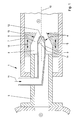
- Fig. 1 device 1 is used for gluing of here not as such illustrated fibers that pass from a refiner 2 in a blowpipe 3.
- the fibers are digested from a feedstock, typically woodchip, under the action of water under elevated pressure and elevated temperature.
- they are discharged with partial relaxation of the pressure prevailing in the refiner 2 overpressure in the blowpipe 3, wherein the water used for the digestion of the fibers evaporates substantially to water vapor.
- the resulting volume expansion results in the fibers suspended in the water vapor entering the blowpipe 3 at high speed and passing therethrough.
- a blowing valve which is usually provided at the outlet of the refiner 2 is omitted.
- the blowpipe 3 has at its input a constriction 4, in the region of which the free cross section of the blower tube 3 is reduced below the free cross section of a connecting piece 5 of the refiner 2 or at least can be reduced.
- the narrowing of the free cross section the blower tube 3 is effected on the one hand by a body 6 which is arranged in the blower tube 3 and in which a conically tapered section of its free cross section adjoins a cylindrical section 8 of its free cross section in the direction away from the refiner 2.
- a nozzle 9 which is arranged on the axis 10 of the blower tube 3, and which serves for spraying a binder 11, which is indicated here only by an arrow, on the coming of the refiner 2 fibers.
- the mouth 12 of the nozzle 9 is directed away from the refiner 2 and it is located in front of the narrowest point of a constricted by the conical portion 7 of the body 6 constriction 13 of the free cross section of the blowpipe 3, but after a narrowest point of the constriction 4 of the free Cross-section of the blower tube 3, which is additionally restricted by the nozzle 9.
- the binder 11 For optimum utilization of the binder 11, ie for realizing a fiberboard made of the glued fibers in relation to a desired quality, it is necessary to distribute the binder as homogeneously as possible over the fibers. This in turn requires the finest possible atomization of the binder. This atomization is effected in the device 1 according to FIG. 1 only in part by a swirl 14 in the nozzle 9 and the nozzle 9 or the pressure drop at its mouth 12. Another essential part of the atomization of the binder 11 is based on the water vapor suspension of the fiber particles which strikes the binder 11 at its high rate of expansion.
- Suitable binders are all binders customary in the field of production of shaped bodies of glued fibers, in particular binders containing NCO groups, which are used in particular for the production of medium-density fiberboard on a large scale and which lead to fibreboards of high quality, but with the disadvantage of relatively high costs.
- the body 6 is displaceable along the axis 10 of the blower tube 3 along its wall 15, which is indicated by double arrows 16.
- the total existing constriction 4 of the blower tube 3 and on the other hand, the position of the mouth 12 of the nozzle is varied relative to the narrowest point of the taper 13 of the body 6. This has both effects on the pressure drop when the fibers exit the refiner 2 into the blower tube 3 and also on the degree of atomization of the binder 11 by the expanding steam suspension of the fibers.
- a device 1 corresponding to FIG. 1 for gluing the fibers can also be formed somewhere in the course of the blower tube 3 from a body 6 which constricts the cross section of the blower tube 3 and together with a nozzle 9 for atomizing the binder 11, which leads to the constriction 4 of the blower tube 3 contributes, be trained.
- the body 6 can be displaceable relative to the nozzle 9 along the axis 10 of the blower tube 3 in order to provide a variable parameter for optimizing the function of the device 1.
- a device 1 arranged in the course of the blower tube 3 differs in terms of its function from the specific embodiment according to FIG. 1 in that a water vapor suspension of the fibers already enters the region of the constriction 4 and is thereby accelerated and also compressed again.
- the embodiment of the apparatus 1 for gluing fibers illustrated in FIG. 2 differs from that according to FIG. 1 in that it is not provided at the beginning, but at the end of the blower tube 3, specifically where the fibers from the blower tube 23 enter into a dryer 17 not shown here to reduce the fiber moisture content of the fibers.
- the body 6 is seated on an end piece 18 of the blower tube 3, the nozzle 9 protruding into the body 6.
- the hydrogen suspension of the fibers from the blower tube 3 is accelerated and compressed in the region of the constriction 4, wherein the pressure increase at the end of the constriction 4 in the dryer 17 degrades again with additional acceleration of the steam suspension.
Landscapes
- Chemical & Material Sciences (AREA)
- Chemical Kinetics & Catalysis (AREA)
- Dispersion Chemistry (AREA)
- Life Sciences & Earth Sciences (AREA)
- Engineering & Computer Science (AREA)
- Manufacturing & Machinery (AREA)
- Wood Science & Technology (AREA)
- Forests & Forestry (AREA)
- Dry Formation Of Fiberboard And The Like (AREA)
- Nonwoven Fabrics (AREA)
Applications Claiming Priority (1)
| Application Number | Priority Date | Filing Date | Title |
|---|---|---|---|
| DE102006026124A DE102006026124A1 (de) | 2006-06-03 | 2006-06-03 | Verfahren und Vorrichtung zur Beleimung von Partikeln im Bereich eines Blasrohrs |
Publications (2)
| Publication Number | Publication Date |
|---|---|
| EP1862214A2 true EP1862214A2 (fr) | 2007-12-05 |
| EP1862214A3 EP1862214A3 (fr) | 2008-07-02 |
Family
ID=38458043
Family Applications (1)
| Application Number | Title | Priority Date | Filing Date |
|---|---|---|---|
| EP07010867A Withdrawn EP1862214A3 (fr) | 2006-06-03 | 2007-06-01 | Procédé et dispositif destinés à relier des fibres dans la zone d'un tube de soufflage |
Country Status (2)
| Country | Link |
|---|---|
| EP (1) | EP1862214A3 (fr) |
| DE (1) | DE102006026124A1 (fr) |
Cited By (5)
| Publication number | Priority date | Publication date | Assignee | Title |
|---|---|---|---|---|
| DE202008015419U1 (de) | 2008-11-21 | 2010-04-22 | Epple, Albrecht, Dr. | Vorrichtung zur Beleimung von Fasern in einem Blasrohr |
| EP2213431A3 (fr) * | 2009-01-29 | 2010-10-27 | Dieffenbacher GmbH + Co. KG | Procédé de fonctionnement d'une installation de fabrication de plaques en fibres, en MDF, en HDF, en matériau dérivé du bois ou en plastique à partir de fibres ou de matériau semblable à la fibre |
| WO2011036200A1 (fr) * | 2009-09-23 | 2011-03-31 | Siempelkamp Maschinen- Und Anlagenbau Gmbh & Co. Kg | Procédé de production de panneaux de fibres de type carton en fibres de bois |
| CN114514101A (zh) * | 2019-09-30 | 2022-05-17 | 安德里茨股份公司 | 在纤维材料上涂抹胶水的设备和方法 |
| WO2026058101A1 (fr) * | 2024-09-12 | 2026-03-19 | Hygienio S.R.L. | Dispositif de mélange pour l'application d'un agent d'action de surface par vaporisation |
Families Citing this family (2)
| Publication number | Priority date | Publication date | Assignee | Title |
|---|---|---|---|---|
| DE102015201464B4 (de) | 2015-01-28 | 2016-10-20 | Brav-O-Tech Gmbh | Vorrichtung und Verfahren zum Beleimen von Partikeln |
| DE102015212798B4 (de) | 2015-07-08 | 2017-02-02 | Brav-O-Tech Gmbh | Vorrichtung und Verfahren zum Benetzen von Partikeln |
Citations (3)
| Publication number | Priority date | Publication date | Assignee | Title |
|---|---|---|---|---|
| DE1632450A1 (de) | 1968-02-10 | 1970-12-10 | Draiswerke Gmbh | Vorrichtung zum kontinuierlichen Mischen relativ kleiner Mengen einer feinteiligen Komponente mit einem durch einen Luftstrom bewegten Traegerstoff |
| EP0078960A1 (fr) | 1981-11-05 | 1983-05-18 | Ag Bayer | Procédé d'encollage de fibres, en particulier des copeaux, et appareillage pour la mise en oeuvre de ce procédé |
| DE10341960A1 (de) | 2003-09-11 | 2005-04-14 | Glunz Ag | Mischverfahren und statischer Mischer, insbesondere zur Beleimung von lignocellulosehaltigen Fasern mit einem Bindemittel |
Family Cites Families (2)
| Publication number | Priority date | Publication date | Assignee | Title |
|---|---|---|---|---|
| DE1208294B (de) * | 1963-02-13 | 1966-01-05 | Gubela Chemie K G | Vorrichtung zum Mischen bzw. Verbinden von gasfoermigen, fluessigen oder festen Komponenten, insbesondere von Fluessigkeiten |
| US6082713A (en) * | 1998-10-03 | 2000-07-04 | Komax Systems, Inc. | Steam injection heater |
-
2006
- 2006-06-03 DE DE102006026124A patent/DE102006026124A1/de not_active Withdrawn
-
2007
- 2007-06-01 EP EP07010867A patent/EP1862214A3/fr not_active Withdrawn
Patent Citations (3)
| Publication number | Priority date | Publication date | Assignee | Title |
|---|---|---|---|---|
| DE1632450A1 (de) | 1968-02-10 | 1970-12-10 | Draiswerke Gmbh | Vorrichtung zum kontinuierlichen Mischen relativ kleiner Mengen einer feinteiligen Komponente mit einem durch einen Luftstrom bewegten Traegerstoff |
| EP0078960A1 (fr) | 1981-11-05 | 1983-05-18 | Ag Bayer | Procédé d'encollage de fibres, en particulier des copeaux, et appareillage pour la mise en oeuvre de ce procédé |
| DE10341960A1 (de) | 2003-09-11 | 2005-04-14 | Glunz Ag | Mischverfahren und statischer Mischer, insbesondere zur Beleimung von lignocellulosehaltigen Fasern mit einem Bindemittel |
Cited By (7)
| Publication number | Priority date | Publication date | Assignee | Title |
|---|---|---|---|---|
| DE202008015419U1 (de) | 2008-11-21 | 2010-04-22 | Epple, Albrecht, Dr. | Vorrichtung zur Beleimung von Fasern in einem Blasrohr |
| EP2213431A3 (fr) * | 2009-01-29 | 2010-10-27 | Dieffenbacher GmbH + Co. KG | Procédé de fonctionnement d'une installation de fabrication de plaques en fibres, en MDF, en HDF, en matériau dérivé du bois ou en plastique à partir de fibres ou de matériau semblable à la fibre |
| CN101863067B (zh) * | 2009-01-29 | 2015-09-09 | 迪芬巴赫有限两合公司 | 制造纤维板、mdf、hdf、木质材料板或塑料板的设备及操作该设备的方法 |
| WO2011036200A1 (fr) * | 2009-09-23 | 2011-03-31 | Siempelkamp Maschinen- Und Anlagenbau Gmbh & Co. Kg | Procédé de production de panneaux de fibres de type carton en fibres de bois |
| CN114514101A (zh) * | 2019-09-30 | 2022-05-17 | 安德里茨股份公司 | 在纤维材料上涂抹胶水的设备和方法 |
| CN114514101B (zh) * | 2019-09-30 | 2023-03-28 | 安德里茨股份公司 | 在纤维材料上涂抹胶水的设备和方法 |
| WO2026058101A1 (fr) * | 2024-09-12 | 2026-03-19 | Hygienio S.R.L. | Dispositif de mélange pour l'application d'un agent d'action de surface par vaporisation |
Also Published As
| Publication number | Publication date |
|---|---|
| DE102006026124A1 (de) | 2007-12-06 |
| EP1862214A3 (fr) | 2008-07-02 |
Similar Documents
| Publication | Publication Date | Title |
|---|---|---|
| EP2213431B1 (fr) | Procédé et installation pour la fabrication de plaques en fibres, en MDF, en HDF, en matériau dérivé du bois ou en plastique à partir de fibres ou de matériau semblable à la fibre | |
| EP0728562B1 (fr) | Appareil et procédé pour mouiller des particules avec un liquide | |
| DE4040242A1 (de) | Verfahren und vorrichtung zur herstellung von feinstfasern aus thermoplastischen polymeren | |
| DE10153593A1 (de) | Verfahren und Vorrichtung zum Benetzen von Holzfasern mit einem Bindemittelfluid | |
| DE69607514T2 (de) | Klebevorrichtung für Faserplattenherstellungsanlagen, und Anlage in welcher sie angewandt wird | |
| DE4122842C2 (de) | Verfahren zur Herstellung von Faserplatten aus stückigen Holzpartikeln und Isocyanat als Bindemittel | |
| EP2431144B1 (fr) | Procédé et dispositif destinés au collage humide de fibres en bois | |
| DE202008015419U1 (de) | Vorrichtung zur Beleimung von Fasern in einem Blasrohr | |
| WO2004052603A1 (fr) | Installation d'encollage de fibres destinee a la production de panneaux de fibres, notamment de panneaux mdf | |
| DE102006013567B4 (de) | Verfahren und Vorrichtung zum Aufbringen von Bindemittel auf Partikel, insbesondere Fasern, die durch einen Blasgang gefördert werden | |
| DE102006026124A1 (de) | Verfahren und Vorrichtung zur Beleimung von Partikeln im Bereich eines Blasrohrs | |
| DE3137109C2 (fr) | ||
| DE102016010539B3 (de) | Verfahren und Vorrichtung zum Beleimen von zur Herstellung von Faserplatten vorgesehenen, getrockneten Fasern | |
| DE10226820B3 (de) | Verfahren und Vorrichtung zum Beleimen von zur Herstellung von Faserplatten vorgesehenen, getrockneten Fasern | |
| EP1514592B1 (fr) | Procédé et dispositif de mélange statique, en particulier pour l'encollage des fibres lignocellulosiques en utilisant un liant | |
| WO2016120046A2 (fr) | Dispositif et procédé d'encollage de particules | |
| DE68902404T2 (de) | Blasenduese zum zerfasern von material. | |
| DE19604902C2 (de) | Zweistoffdüse | |
| DE102004001527A1 (de) | Anlage und Verfahren zum Beleimen von Fasern für die Herstellung von Faserplatten, insbesondere MDF-Platten u. dgl. Holzwerkstoffplatten | |
| DE1235214B (de) | Verfahren zur Herstellung von Mischungen aus Feststoffen und bituminoesen Bindemitteln und Mischduese zu seiner Durchfuehrung | |
| DE3515346A1 (de) | Vorrichtung zur herstellung von feinen mineralfasern | |
| DE102015212798B4 (de) | Vorrichtung und Verfahren zum Benetzen von Partikeln | |
| DE19655254B4 (de) | Zweistoffdüse | |
| EP4008510B1 (fr) | Procédé de pulvérisation d'un liant liquide et dispositif de collage | |
| DE102017103458A1 (de) | Vorrichtung und Verfahren zum Benetzen eines Materialstroms mit einem Bindemittel und einem System zur Herstellung von Werkstoffplatten |
Legal Events
| Date | Code | Title | Description |
|---|---|---|---|
| PUAI | Public reference made under article 153(3) epc to a published international application that has entered the european phase |
Free format text: ORIGINAL CODE: 0009012 |
|
| AK | Designated contracting states |
Kind code of ref document: A2 Designated state(s): AT BE BG CH CY CZ DE DK EE ES FI FR GB GR HU IE IS IT LI LT LU LV MC MT NL PL PT RO SE SI SK TR |
|
| AX | Request for extension of the european patent |
Extension state: AL BA HR MK YU |
|
| PUAL | Search report despatched |
Free format text: ORIGINAL CODE: 0009013 |
|
| AK | Designated contracting states |
Kind code of ref document: A3 Designated state(s): AT BE BG CH CY CZ DE DK EE ES FI FR GB GR HU IE IS IT LI LT LU LV MC MT NL PL PT RO SE SI SK TR |
|
| AX | Request for extension of the european patent |
Extension state: AL BA HR MK RS |
|
| 17P | Request for examination filed |
Effective date: 20081230 |
|
| AKX | Designation fees paid |
Designated state(s): AT BE BG CH CY CZ DE DK EE ES FI FR GB GR HU IE IS IT LI LT LU LV MC MT NL PL PT RO SE SI SK TR |
|
| 17Q | First examination report despatched |
Effective date: 20090310 |
|
| GRAP | Despatch of communication of intention to grant a patent |
Free format text: ORIGINAL CODE: EPIDOSNIGR1 |
|
| GRAS | Grant fee paid |
Free format text: ORIGINAL CODE: EPIDOSNIGR3 |
|
| STAA | Information on the status of an ep patent application or granted ep patent |
Free format text: STATUS: THE APPLICATION IS DEEMED TO BE WITHDRAWN |
|
| 18D | Application deemed to be withdrawn |
Effective date: 20101020 |