EP1862257A1 - Einsatz zum Bandschleifen verschiedener Materialien - Google Patents
Einsatz zum Bandschleifen verschiedener Materialien Download PDFInfo
- Publication number
- EP1862257A1 EP1862257A1 EP07300967A EP07300967A EP1862257A1 EP 1862257 A1 EP1862257 A1 EP 1862257A1 EP 07300967 A EP07300967 A EP 07300967A EP 07300967 A EP07300967 A EP 07300967A EP 1862257 A1 EP1862257 A1 EP 1862257A1
- Authority
- EP
- European Patent Office
- Prior art keywords
- cloth
- insert
- machining
- axis
- determined
- Prior art date
- Legal status (The legal status is an assumption and is not a legal conclusion. Google has not performed a legal analysis and makes no representation as to the accuracy of the status listed.)
- Granted
Links
- 239000004744 fabric Substances 0.000 title claims abstract description 98
- 239000000463 material Substances 0.000 title claims abstract description 43
- 238000003754 machining Methods 0.000 claims abstract description 56
- 238000003825 pressing Methods 0.000 claims abstract description 7
- 239000010431 corundum Substances 0.000 claims description 9
- 229910052593 corundum Inorganic materials 0.000 claims description 9
- 230000004907 flux Effects 0.000 claims description 5
- 210000002105 tongue Anatomy 0.000 claims description 5
- 230000000295 complement effect Effects 0.000 claims description 4
- 239000010432 diamond Substances 0.000 claims description 4
- 229910003460 diamond Inorganic materials 0.000 claims description 4
- 238000007493 shaping process Methods 0.000 abstract 1
- 235000019589 hardness Nutrition 0.000 description 13
- 230000011218 segmentation Effects 0.000 description 4
- 238000005299 abrasion Methods 0.000 description 3
- 238000012937 correction Methods 0.000 description 3
- 210000002445 nipple Anatomy 0.000 description 2
- 238000005498 polishing Methods 0.000 description 2
- 230000009467 reduction Effects 0.000 description 2
- 238000005406 washing Methods 0.000 description 2
- 239000000956 alloy Substances 0.000 description 1
- 229910045601 alloy Inorganic materials 0.000 description 1
- 230000008859 change Effects 0.000 description 1
- 230000007547 defect Effects 0.000 description 1
- 239000013013 elastic material Substances 0.000 description 1
- 229920001971 elastomer Polymers 0.000 description 1
- 239000000806 elastomer Substances 0.000 description 1
- 239000004519 grease Substances 0.000 description 1
- 238000003780 insertion Methods 0.000 description 1
- 230000037431 insertion Effects 0.000 description 1
- 238000004519 manufacturing process Methods 0.000 description 1
- 238000000034 method Methods 0.000 description 1
- 230000008569 process Effects 0.000 description 1
- 230000002787 reinforcement Effects 0.000 description 1
- 238000009941 weaving Methods 0.000 description 1
Images

Classifications
-
- B—PERFORMING OPERATIONS; TRANSPORTING
- B24—GRINDING; POLISHING
- B24B—MACHINES, DEVICES, OR PROCESSES FOR GRINDING OR POLISHING; DRESSING OR CONDITIONING OF ABRADING SURFACES; FEEDING OF GRINDING, POLISHING, OR LAPPING AGENTS
- B24B33/00—Honing machines or devices; Accessories therefor
- B24B33/08—Honing tools
- B24B33/083—Honing tools with different sets of honing stones
-
- B—PERFORMING OPERATIONS; TRANSPORTING
- B24—GRINDING; POLISHING
- B24B—MACHINES, DEVICES, OR PROCESSES FOR GRINDING OR POLISHING; DRESSING OR CONDITIONING OF ABRADING SURFACES; FEEDING OF GRINDING, POLISHING, OR LAPPING AGENTS
- B24B5/00—Machines or devices designed for grinding surfaces of revolution on work, including those which also grind adjacent plane surfaces; Accessories therefor
- B24B5/36—Single-purpose machines or devices
- B24B5/42—Single-purpose machines or devices for grinding crankshafts or crankpins
Definitions
- the invention relates to the field of abrasion machining by grinding for the finishing of cylindrical surfaces.
- the invention particularly relates to the superfinishing of cylindrical bearing surfaces, for example of a crankshaft.
- Some cylindrical surfaces such as crankshaft bearings, require machining with severe tolerances. These severe tolerances are obtained, for example, by advanced abrasion processes such as abrasive cloth finishing. Finishing, for example cylindrical scopes, requires on the one hand, a machining operation of the form, during which a removal of material is performed. On the other hand, the finish requires a machining operation of the surface condition, also called superfinishing.
- the finishing is often carried out by pressing an abrasive cloth against the surface to be machined by means of canvas supports, also called cloth inserts, housed in one or more jaws, or pads, or other clamping means.
- the cloth inserts comprise at least one contact surface with the abrasive cloth, in a portion of a cylinder, and press the abrasive cloth pressed against the cylindrical surface to be machined.
- the set of contact surfaces envelope the cylindrical surface to be machined. Relative movement of the workpiece with respect to abrasive surfaces in contact is achieved for finishing. This relative movement is for example a rotation along the axis of the cylindrical surface to be machined, combined with a movement in translation, back and forth, along the same axis.
- the patent application WO 95/21728 discloses an apparatus comprising a plurality of movable arms each associated with a bearing of the same crankshaft and each having a jaw equipped with a set of bearing inserts against the scope to be machined.
- the subject of this patent application is a system for correcting the shape of a bearing surface or a journal to be machined.
- the described system performs in particular a removal of material according to different surface states depending on the hardness of the inserts used.
- inserts used for the removal of material do not allow the machining of the surface state.
- the patent US 5,695,391 discloses a machine for machining the surface state of a cylindrical part, such as a crankshaft bearing.
- This system includes a flexible shell, applying pressure on an abrasive belt against the workpiece.
- the flexible shell adapts to the different shape variations of the workpiece.
- this system does not perform a shape correction of the workpiece.
- the patent EP 1 447 172 describes a machining machine for ultra finishing, using a polishing film.
- the object of the patent is to control the wear of the film and thus the quality of the polishing.
- this system does not perform a shape correction of the workpiece.
- a disadvantage in the precision machining of cylinder parts such as a crankshaft bearing is that existing machine tools require at least one machining step of the form followed by at least one machining step of the state. of surface. These steps generally require at least two different machines, each performing an operation or a complex machine performing several machining cycles.
- the object of the present invention is to overcome several disadvantages of the prior art, by creating a cloth insert that makes it possible simultaneously to perform machining of the form (in a non-limiting manner in terms of cylindricity, taper or facets) and machining of the mold. the surface state of a cylindrical part, allowing a reduction in the machining cycle time and a reduction in the cost of all the machining machines.
- a cloth insert in a finishing machining machine of a cylindrical machining surface of determined axis belonging to a workpiece comprising means for clamping a plurality of cloth inserts. pressing an abrasive cloth pressed against the surface to be machined and means to animate a relative rotational movement along the determined axis and / or translation along the determined axis, the workpiece relative to the cloth inserts, characterized in that the weaving insert comprises at least one contact surface with the concave abrasive fabric composed of at least a first material having a first hardness determined for machining the shape and a second material having a second hardness determined for perform a machining of the surface state.
- the first material contains corundum and / or diamond and the second material contains flux.
- a band of predetermined width extends over the contact surface with the abrasive cloth, the band being constituted by the first material, the sides of the band being parallel to an oblique plane with respect to the determined axis .
- the part of the surface not covered by the strip is constituted by the second material.
- the contact surface with the abrasive cloth, is almost in a cylinder portion of the same axis and of the same radius as the cylindrical surface to be machined, the contact surface is delimited by four sides formed by two parallel segments and on either side of the determined axis and two arcs of circle each connected to the ends of the segments and whose center belongs to the determined axis, the band constituted by the first material connecting two opposite corners of the contact surface.
- the cloth insert comprises a plurality of contact surfaces with the abrasive cloth, separated from each other by at least one chip evacuation groove.
- the cloth insert comprises holding means on a face opposite to the contact surface.
- the cloth insert is bonded by its complementary holding means to an intermediate shoe, the intermediate shoe having fastening means to the clamping means.
- the holding means of the cloth insert comprise tabs and the means for holding the intermediate pad comprise grooves.
- the tongues and grooves are delimited by edges in an arc whose center belongs to the determined axis.
- the holding means of the cloth insert comprise holes having a thread and the means for holding the intermediate shoe comprise screws.
- a second object of the invention is to propose an implementation of the cloth insert according to the invention to perform a machining of a cylindrical surface with a determined surface state.
- each pad and its associated insert are periodically replaced by a similar pad associated with a similar unused insert.
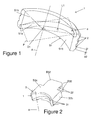
- the insert (1) of the cloth according to the invention comprises a surface (S1), also called the contact surface, pressing the abrasive cloth against the workpiece.
- the contact surface (S1) is in a cylinder portion of the same axis as the axis (A) of the workpiece and of the same radius of curvature.
- the contact surface abutting against the abrasive cloth supported on the other hand on the surface to be machined, the contact surface with the abrasive cloth has the same radius of curvature and the same axis as the machined surface.
- the contact surface (S1) of the cloth insert comprises, in a nonlimiting manner, a first zone (S1a) of a first predetermined hardness and a second and a third zone (S1b) of a determined second hardness.
- the first zone (S1 a) of the surface (S1) is for example made by a layer of corundum and the second and third zones (S1 b) of the surface (S1) are for example made by a layer of gas.
- the first harder material for example corundum
- the second softer material for example the flux
- the first material comprises for example corundum which is a very hard material whose hardness is 9 on the Mohs scale
- the second material comprises, for example, curvane which is a deformable elastic material of the elastomer type.
- the corundum and the flux are used pure or according to an alloy.
- the first zone is, for example, a strip, of a determined width (L1), traversing the surface of contact with the abrasive cloth, diagonally along a plane (P) oblique with respect to the axis (A) of the piece to machine.
- the second and third zones (S1b) cover the remainder of the contact surface (S1).
- the band formed by the first material is for example embedded in the second material and has a thickness (e) determined.
- the contact surface of the cloth insert according to the invention comprises a plurality of bands of different hardness.
- a first band is for example made by a diamond layer
- a second band is for example made by a layer of corundum.
- the remainder of the surface (S1) of contact is formed by zones made in a non-limiting manner by a layer of a third material, for example curvane which, in combination with the abrasive cloth, produces an abrasive surface for superfinishing, coming against the workpiece.
- the insert (1) for stretching extends over a given angle (D1) around the workpiece.
- the insert (1) of the cloth according to the invention comprises elements (2) for holding.
- the elements (2) for holding are for example tabs (2) of rectangular section, intended to be introduced into grooves (31).
- the tongues (2) are placed on one side of the insert (1) of the cloth according to the invention, opposite the contact surface (S1).
- the insert (1) of the cloth, shown in Figure 1 is composed of non-limiting manner of two materials, the first material being inserted into the second material which also carries out, without limitation, the holding elements.
- the grooves are non-limiting, straight and parallel to the axis of the workpiece or in an oblique plane relative to the axis of the workpiece or intersect such a set of grooves being straight and parallel to the axis of the workpiece and the other grooves in an oblique plane relative to the axis of the workpiece.
- the holding elements located on a face opposite to the contact surface, are constituted, in a non-limiting manner, by pins or threaded rods or threaded holes.
- the insert (1) comprises a web (S1) of contact with the abrasive cloth against the workpiece, made by layers of materials of different hardness, as previously described. , but these layers forming the contact surface (S1) are each connected to a connecting element.
- the connecting element is made of a determined material and comprises holding elements (2), for example tabs, on a face opposite to the contact surface.
- each insert (1) of the cloth according to the invention is associated with a not shown jaw or an intermediate shoe (3).
- the intermediate shoe (3) comprises, for example, two tabs (32) for fastening in a clamping tool the inserts (1) of the cloth coming against the abrasive cloth pressed against the workpiece. These two tabs are for example of rectangular section and are fixed in a hole of the same section of the clamping tool.
- the pad also comprises elements (31) for complementary support connected to the elements (2) for holding the insert (1) of the cloth.
- the intermediate shoe (3) comprises, for example, grooves (31) in which the tongues (2) of the insert (1) of the cloth are positioned.
- the holding elements of the intermediate shoe (3) are round section holes, associated with nipples of the insert (1) of the wire, of the same section.
- the holding elements of the intermediate shoe (3) are screws or respectively threaded holes, associated with threaded holes or screws respectively, of the insert (1) of the cloth.
- the intermediate pad has one or more gripping surfaces (S3a, S3b). These gripping surfaces (S3b or S3a) are oriented, for example, parallel or respectively perpendicular to the axis (A).
- the intermediate pad is for example held by an automated clamp exerting a gripping force on these surfaces (S3a, S3b).
- the fastening tabs (32) have edges (B32) beveled to facilitate the centering of the fastening lugs (3) in the clamping tool.
- the clamping lugs are cylindrical pins inserted in holes of the same section of the clamping tool.
- the end of the nipples is tapered to facilitate centering during insertion into the clamping tool.
- the insert (1) of webbing is directly connected by its holding elements (2) to complementary holding elements of a clamping tool, such as a jaw.
- a clamping tool such as a jaw.
- FIG. 3 represents an example of positioning of three intermediate runners (3) each associated with an insert (1) of wire cloth according to the invention.
- the intermediate shoes (3) are held in place by a not shown clamping tool.
- the clamping tool is for example a movable arm.
- the workpiece, not shown, is arranged along its axis (A).
- the set of inserts (1) of cloth according to the invention surrounds the workpiece, the abrasive cloth being disposed between the workpiece and the inserts of the cloth.
- the inserts (1) of cloth according to the invention are distributed in two clamping jaws.
- An arm associated with a jaw makes it possible to perform the machining of a cylindrical surface.
- the inserts (1) of the machine according to the invention are made to adapt to gripping means of a jaw.
- the clamping tool is associated with a tool for measuring the diameter of the cylindrical surface to be machined as described in the patent application. WO 95/21728 or in the patent application EP 0 680 806 .
- a machine for machining cylindrical surfaces for example crankshaft bearings
- a machining arm or a plurality of machining arms as described in FIGS. documents cited in the prior art.
- a machining arm is used to perform the machining of a cylindrical surface, for example a cylindrical bearing of a crankshaft.
- each cylindrical seat of a crankshaft is, for example, associated with an arm to perform the machining of all crankshaft bearings simultaneously.
- the arm is moved to successively perform the machining of distinct cylindrical bearing surfaces.
- Each arm comprises a clamping means exerting a pressure on the inserts (1) of cloth against the abrasive cloth pressed against the cylindrical surface to be machined, for example a cylindrical crankshaft bearing.
- the clamping means is for example a jaw supporting the inserts (1) of the cloth, as described in the patent application.
- a plurality of pads for example four or more, each supporting an insert (1) of cloth according to the invention, are pressed against the abrasive cloth pressed against the workpiece by clamping means.
- the pads are movable relative to the workpiece, along one or more axes of rotation or translation.
- a shoe (3) is, in a nonlimiting manner, rotatable about an axis of rotation parallel to the axis (A) of the workpiece.
- a pad (3) is rotatable along an axis of rotation perpendicular to the axis (A) of the workpiece and passing through this axis (A).
- a shoe (3) is movable in translation along an axis perpendicular to the axis (A) of the workpiece and passing through this axis.
- a pad (3) has several degrees of freedom, allowing precise positioning with respect to the workpiece.
- a machining cycle begins with the tightening of the inserts (1) of cloth according to the invention, by pressing in this way the abrasive cloth against the workpiece. Then the workpiece is set in motion relative to the inserts (1) of cloth, in a non-limiting manner according to a relative rotational movement according to the axis of the surface to be machined or a movement in translation, back and forth, along the axis of the surface to be machined or a combination of these two movements. The cycle continues by stopping the relative movement of the workpiece relative to the inserts (1) of the wire. Then the clamping device is controlled so as to eliminate the tightening of the inserts (1) of the cloth, and therefore of the abrasive cloth against the surface to be machined.
- the machining of the surface is then performed, according to a machining of the form and according to a machining of the surface state.
- the removal of material performing the machining of the shape is performed by the portion of the abrasive cloth pressed by the hard layer of the insert, for example corundum.
- the machining of the surface condition is, for example, carried out by the part of the abrasive cloth pressed against a softer layer, for example in a curvane.
- the abrasive cloth is then renewed partially according to a determined indexing or completely. Renewal is performed, without limitation, automatically. In a nonlimiting manner, a new part is then machined in the same way.
- the intermediate pads (3), each associated with a worn insert (1) are removed and each replaced by a pad (3) associated with a cloth insert (1) not worn.
- the worn insert is separated from the intermediate shoe (3) and replaced by an unused cloth insert (1), so that the shoe (3) is reused later.
- a plurality of clamping tools each tighten a crankshaft bearing to simultaneously perform the machining of a plurality of crankshaft bearing surfaces.
- machining cycle of the shape and the surface condition is therefore shorter.
- a cycle of washing with hard inserts is indeed followed by a cycle of washing with soft inserts.
- Two machines operating one after the other or a longer cycle with a change of insert are then necessary.
- the combination of at least two materials of different hardness involves only one machining cycle.
- the hard layer of the insert ensures a significant removal of material, and corrections of shape (in a non-limiting manner in terms of straightness, cylindricity, circularity or facets).
- the softer layer provides a high surface quality, even with respect to the grease holes of the crankshaft bearings, and limits the relative sliding between the abrasive cloth and the surface of the insert.
- the machining of the shape or surface condition generates chips.
- the chips are evacuated at the level of the areas on which no insert (1) of clothage applies pressure.
- a segmentation is performed, as shown in Figure 4.
- the segmentation of the insert (1) of the wire is the realization of grooves (F) in the insert (1) of the wire.
- the grooves (F) are, without limitation, parallel to the axis of the workpiece or in an oblique plane relative to this axis. Segmentation facilitates firstly the manufacture of the inserts (1) of cloth according to the invention and secondly the segmentation facilitates the evacuation of chips during machining.
- the reinforcement insert (1) according to the invention is segmented by two grooves (F) sharing the contact surface in three sub-surfaces, each traversed by a diagonal band of one first material, for example corundum, the remainder being made in a second material, for example, flux.
- the positions of the hardest material and the softest material are reversed. Different geometrical configurations are possible. The choice of the hardnesses of the two materials determines the removal of material and the surface condition of the finished cylindrical surface.
Landscapes
- Engineering & Computer Science (AREA)
- Mechanical Engineering (AREA)
- Finish Polishing, Edge Sharpening, And Grinding By Specific Grinding Devices (AREA)
- Shafts, Cranks, Connecting Bars, And Related Bearings (AREA)
- Grinding Of Cylindrical And Plane Surfaces (AREA)
- Polishing Bodies And Polishing Tools (AREA)
- Laminated Bodies (AREA)
Applications Claiming Priority (1)
| Application Number | Priority Date | Filing Date | Title |
|---|---|---|---|
| FR0604752A FR2901500B1 (fr) | 2006-05-29 | 2006-05-29 | Insert de toilage multi materiau |
Publications (2)
| Publication Number | Publication Date |
|---|---|
| EP1862257A1 true EP1862257A1 (de) | 2007-12-05 |
| EP1862257B1 EP1862257B1 (de) | 2010-06-09 |
Family
ID=37507787
Family Applications (1)
| Application Number | Title | Priority Date | Filing Date |
|---|---|---|---|
| EP07300967A Ceased EP1862257B1 (de) | 2006-05-29 | 2007-04-20 | Einsatz zum Bandschleifen verschiedener Materialien |
Country Status (4)
| Country | Link |
|---|---|
| EP (1) | EP1862257B1 (de) |
| AT (1) | ATE470535T1 (de) |
| DE (1) | DE602007007012D1 (de) |
| FR (1) | FR2901500B1 (de) |
Cited By (1)
| Publication number | Priority date | Publication date | Assignee | Title |
|---|---|---|---|---|
| US9505989B2 (en) | 2011-11-08 | 2016-11-29 | Exxonmobil Upstream Research Company | Processing a hydrocarbon stream using supercritical water |
Families Citing this family (1)
| Publication number | Priority date | Publication date | Assignee | Title |
|---|---|---|---|---|
| EP2327510B1 (de) * | 2009-11-25 | 2011-07-06 | Supfina Grieshaber GmbH & Co. KG | Finishvorrichtung |
Citations (4)
| Publication number | Priority date | Publication date | Assignee | Title |
|---|---|---|---|---|
| DE1958056A1 (de) * | 1969-11-19 | 1971-05-27 | Nagel Wolf | Honwerkzeug zum Aussenhonen |
| EP0138237A1 (de) * | 1983-07-20 | 1985-04-24 | HS VEGLIO S.r.l. | Diamantbezetzte Segmente und Einsätze |
| WO1995021728A1 (en) * | 1992-05-20 | 1995-08-17 | Barton Kenneth A Ii | Method and apparatus for correcting diametrical taper on a workpiece |
| GB2310626A (en) * | 1996-03-01 | 1997-09-03 | Nagel Masch Werkzeug | Device for the finishing of workpieces |
-
2006
- 2006-05-29 FR FR0604752A patent/FR2901500B1/fr not_active Expired - Fee Related
-
2007
- 2007-04-20 AT AT07300967T patent/ATE470535T1/de not_active IP Right Cessation
- 2007-04-20 EP EP07300967A patent/EP1862257B1/de not_active Ceased
- 2007-04-20 DE DE602007007012T patent/DE602007007012D1/de active Active
Patent Citations (4)
| Publication number | Priority date | Publication date | Assignee | Title |
|---|---|---|---|---|
| DE1958056A1 (de) * | 1969-11-19 | 1971-05-27 | Nagel Wolf | Honwerkzeug zum Aussenhonen |
| EP0138237A1 (de) * | 1983-07-20 | 1985-04-24 | HS VEGLIO S.r.l. | Diamantbezetzte Segmente und Einsätze |
| WO1995021728A1 (en) * | 1992-05-20 | 1995-08-17 | Barton Kenneth A Ii | Method and apparatus for correcting diametrical taper on a workpiece |
| GB2310626A (en) * | 1996-03-01 | 1997-09-03 | Nagel Masch Werkzeug | Device for the finishing of workpieces |
Cited By (1)
| Publication number | Priority date | Publication date | Assignee | Title |
|---|---|---|---|---|
| US9505989B2 (en) | 2011-11-08 | 2016-11-29 | Exxonmobil Upstream Research Company | Processing a hydrocarbon stream using supercritical water |
Also Published As
| Publication number | Publication date |
|---|---|
| FR2901500B1 (fr) | 2009-02-06 |
| ATE470535T1 (de) | 2010-06-15 |
| EP1862257B1 (de) | 2010-06-09 |
| FR2901500A1 (fr) | 2007-11-30 |
| DE602007007012D1 (de) | 2010-07-22 |
Similar Documents
| Publication | Publication Date | Title |
|---|---|---|
| JP5476432B2 (ja) | 平坦なワークピースを両面加工する装置、ならびに複数の半導体ウェハを両面で同時に材料切削加工する方法 | |
| KR101565026B1 (ko) | 양면 연마 장치용 캐리어 및 이를 이용한 양면 연마 장치, 및 양면 연마 방법 | |
| EP0640435B1 (de) | Schleifmaschine | |
| CN103201071B (zh) | 超精加工装置和加工方法及具有超精加工滚道面的轴承的外圈 | |
| US20120100788A1 (en) | Manufacturing method of carrier for double-side polishing apparatus, carrier for double-side polishing apparatus, and double-side polishing method of wafer | |
| FR2690639A1 (fr) | Dispositif pour le travail de finition du pourtour de verres de lunettes. | |
| JP2012513310A (ja) | 平坦なワークピースの両面用研削加工装置 | |
| EP1852900B1 (de) | Träger für eine doppelseitige poliermaschine und diesen verwendende doppelseitige poliermaschine und verfahren zum doppelseitigen polieren | |
| EP1862257B1 (de) | Einsatz zum Bandschleifen verschiedener Materialien | |
| EP0787562B1 (de) | Doppelseitenpoliermaschine und Verfahren zum Polieren von gegenüberliegenden Seiten eines Werkstückes mittels derselben | |
| EP0993907A1 (de) | Vorrichtung zum polieren des umfangs eines werkstückes | |
| FR2465563A1 (fr) | Procede et appareil de montage de plaquettes a polir | |
| FR3067630A1 (fr) | Tampon de polissage a rainures obliques | |
| EP1984147B1 (de) | Verfahren zum satinieren eines harten materials | |
| FR3067627A1 (fr) | Procede de polissage cmp a haut debit | |
| TWI300737B (en) | Method for the material-removing machining of a semiconductor wafer | |
| EP0856379B1 (de) | Schleifband Vorrichtung zum Bearbeiten einer cylindrischen Lageroberfläche eines Werkstückes | |
| FR2725047A1 (fr) | Procede et dispositif pour obvier a la fragilite des aretes d'une lentille ophtalmique, et lentille ophtalmique correspondante | |
| EP0238395B1 (de) | Werkzeug zur automatischen Entgratung von Turbomaschinen-Schaufeln | |
| EP3608060B1 (de) | Bearbeitungswerkzeug zum schleifen eines werkstücks | |
| KR100746373B1 (ko) | 양면 연마장치의 캐리어 플레이트 구조 | |
| JP2024524041A5 (de) | ||
| JP5210250B2 (ja) | バリ取り装置 | |
| FR2553019A1 (fr) | Procede pour la fabrication d'un outil en forme de roue dentee, de tige dentee ou de vis sans fin, pour le travail de finition de flancs de dents de roues dentees, specialement de roues trempees, et outil ainsi fabrique | |
| JP2005005398A (ja) | 研磨装置およびリテナーリング |
Legal Events
| Date | Code | Title | Description |
|---|---|---|---|
| PUAI | Public reference made under article 153(3) epc to a published international application that has entered the european phase |
Free format text: ORIGINAL CODE: 0009012 |
|
| AK | Designated contracting states |
Kind code of ref document: A1 Designated state(s): AT BE BG CH CY CZ DE DK EE ES FI FR GB GR HU IE IS IT LI LT LU LV MC MT NL PL PT RO SE SI SK TR |
|
| AX | Request for extension of the european patent |
Extension state: AL BA HR MK YU |
|
| 17P | Request for examination filed |
Effective date: 20080521 |
|
| 17Q | First examination report despatched |
Effective date: 20080619 |
|
| AKX | Designation fees paid |
Designated state(s): AT BE BG CH CY CZ DE DK EE ES FI FR GB GR HU IE IS IT LI LT LU LV MC MT NL PL PT RO SE SI SK TR |
|
| GRAP | Despatch of communication of intention to grant a patent |
Free format text: ORIGINAL CODE: EPIDOSNIGR1 |
|
| GRAS | Grant fee paid |
Free format text: ORIGINAL CODE: EPIDOSNIGR3 |
|
| GRAA | (expected) grant |
Free format text: ORIGINAL CODE: 0009210 |
|
| AK | Designated contracting states |
Kind code of ref document: B1 Designated state(s): AT BE BG CH CY CZ DE DK EE ES FI FR GB GR HU IE IS IT LI LT LU LV MC MT NL PL PT RO SE SI SK TR |
|
| REG | Reference to a national code |
Ref country code: CH Ref legal event code: EP |
|
| REG | Reference to a national code |
Ref country code: IE Ref legal event code: FG4D Free format text: LANGUAGE OF EP DOCUMENT: FRENCH |
|
| REF | Corresponds to: |
Ref document number: 602007007012 Country of ref document: DE Date of ref document: 20100722 Kind code of ref document: P |
|
| REG | Reference to a national code |
Ref country code: NL Ref legal event code: VDEP Effective date: 20100609 |
|
| PG25 | Lapsed in a contracting state [announced via postgrant information from national office to epo] |
Ref country code: LT Free format text: LAPSE BECAUSE OF FAILURE TO SUBMIT A TRANSLATION OF THE DESCRIPTION OR TO PAY THE FEE WITHIN THE PRESCRIBED TIME-LIMIT Effective date: 20100609 Ref country code: SE Free format text: LAPSE BECAUSE OF FAILURE TO SUBMIT A TRANSLATION OF THE DESCRIPTION OR TO PAY THE FEE WITHIN THE PRESCRIBED TIME-LIMIT Effective date: 20100609 |
|
| LTIE | Lt: invalidation of european patent or patent extension |
Effective date: 20100609 |
|
| PG25 | Lapsed in a contracting state [announced via postgrant information from national office to epo] |
Ref country code: LV Free format text: LAPSE BECAUSE OF FAILURE TO SUBMIT A TRANSLATION OF THE DESCRIPTION OR TO PAY THE FEE WITHIN THE PRESCRIBED TIME-LIMIT Effective date: 20100609 Ref country code: FI Free format text: LAPSE BECAUSE OF FAILURE TO SUBMIT A TRANSLATION OF THE DESCRIPTION OR TO PAY THE FEE WITHIN THE PRESCRIBED TIME-LIMIT Effective date: 20100609 Ref country code: AT Free format text: LAPSE BECAUSE OF FAILURE TO SUBMIT A TRANSLATION OF THE DESCRIPTION OR TO PAY THE FEE WITHIN THE PRESCRIBED TIME-LIMIT Effective date: 20100609 Ref country code: SI Free format text: LAPSE BECAUSE OF FAILURE TO SUBMIT A TRANSLATION OF THE DESCRIPTION OR TO PAY THE FEE WITHIN THE PRESCRIBED TIME-LIMIT Effective date: 20100609 |
|
| PG25 | Lapsed in a contracting state [announced via postgrant information from national office to epo] |
Ref country code: CY Free format text: LAPSE BECAUSE OF FAILURE TO SUBMIT A TRANSLATION OF THE DESCRIPTION OR TO PAY THE FEE WITHIN THE PRESCRIBED TIME-LIMIT Effective date: 20100609 Ref country code: PL Free format text: LAPSE BECAUSE OF FAILURE TO SUBMIT A TRANSLATION OF THE DESCRIPTION OR TO PAY THE FEE WITHIN THE PRESCRIBED TIME-LIMIT Effective date: 20100609 |
|
| REG | Reference to a national code |
Ref country code: IE Ref legal event code: FD4D |
|
| PG25 | Lapsed in a contracting state [announced via postgrant information from national office to epo] |
Ref country code: NL Free format text: LAPSE BECAUSE OF FAILURE TO SUBMIT A TRANSLATION OF THE DESCRIPTION OR TO PAY THE FEE WITHIN THE PRESCRIBED TIME-LIMIT Effective date: 20100609 Ref country code: IE Free format text: LAPSE BECAUSE OF FAILURE TO SUBMIT A TRANSLATION OF THE DESCRIPTION OR TO PAY THE FEE WITHIN THE PRESCRIBED TIME-LIMIT Effective date: 20100609 Ref country code: EE Free format text: LAPSE BECAUSE OF FAILURE TO SUBMIT A TRANSLATION OF THE DESCRIPTION OR TO PAY THE FEE WITHIN THE PRESCRIBED TIME-LIMIT Effective date: 20100609 |
|
| PG25 | Lapsed in a contracting state [announced via postgrant information from national office to epo] |
Ref country code: PT Free format text: LAPSE BECAUSE OF FAILURE TO SUBMIT A TRANSLATION OF THE DESCRIPTION OR TO PAY THE FEE WITHIN THE PRESCRIBED TIME-LIMIT Effective date: 20101011 Ref country code: SK Free format text: LAPSE BECAUSE OF FAILURE TO SUBMIT A TRANSLATION OF THE DESCRIPTION OR TO PAY THE FEE WITHIN THE PRESCRIBED TIME-LIMIT Effective date: 20100609 Ref country code: CZ Free format text: LAPSE BECAUSE OF FAILURE TO SUBMIT A TRANSLATION OF THE DESCRIPTION OR TO PAY THE FEE WITHIN THE PRESCRIBED TIME-LIMIT Effective date: 20100609 Ref country code: IS Free format text: LAPSE BECAUSE OF FAILURE TO SUBMIT A TRANSLATION OF THE DESCRIPTION OR TO PAY THE FEE WITHIN THE PRESCRIBED TIME-LIMIT Effective date: 20101009 Ref country code: RO Free format text: LAPSE BECAUSE OF FAILURE TO SUBMIT A TRANSLATION OF THE DESCRIPTION OR TO PAY THE FEE WITHIN THE PRESCRIBED TIME-LIMIT Effective date: 20100609 |
|
| PG25 | Lapsed in a contracting state [announced via postgrant information from national office to epo] |
Ref country code: IT Free format text: LAPSE BECAUSE OF FAILURE TO SUBMIT A TRANSLATION OF THE DESCRIPTION OR TO PAY THE FEE WITHIN THE PRESCRIBED TIME-LIMIT Effective date: 20100609 |
|
| PLBE | No opposition filed within time limit |
Free format text: ORIGINAL CODE: 0009261 |
|
| STAA | Information on the status of an ep patent application or granted ep patent |
Free format text: STATUS: NO OPPOSITION FILED WITHIN TIME LIMIT |
|
| PG25 | Lapsed in a contracting state [announced via postgrant information from national office to epo] |
Ref country code: DK Free format text: LAPSE BECAUSE OF FAILURE TO SUBMIT A TRANSLATION OF THE DESCRIPTION OR TO PAY THE FEE WITHIN THE PRESCRIBED TIME-LIMIT Effective date: 20100609 Ref country code: GR Free format text: LAPSE BECAUSE OF FAILURE TO SUBMIT A TRANSLATION OF THE DESCRIPTION OR TO PAY THE FEE WITHIN THE PRESCRIBED TIME-LIMIT Effective date: 20100910 |
|
| REG | Reference to a national code |
Ref country code: DE Ref legal event code: R097 Ref document number: 602007007012 Country of ref document: DE Effective date: 20110309 |
|
| BERE | Be: lapsed |
Owner name: RENAULT SAS Effective date: 20110430 |
|
| PG25 | Lapsed in a contracting state [announced via postgrant information from national office to epo] |
Ref country code: MC Free format text: LAPSE BECAUSE OF NON-PAYMENT OF DUE FEES Effective date: 20110430 |
|
| REG | Reference to a national code |
Ref country code: CH Ref legal event code: PL |
|
| PG25 | Lapsed in a contracting state [announced via postgrant information from national office to epo] |
Ref country code: MT Free format text: LAPSE BECAUSE OF FAILURE TO SUBMIT A TRANSLATION OF THE DESCRIPTION OR TO PAY THE FEE WITHIN THE PRESCRIBED TIME-LIMIT Effective date: 20100609 |
|
| PG25 | Lapsed in a contracting state [announced via postgrant information from national office to epo] |
Ref country code: LI Free format text: LAPSE BECAUSE OF NON-PAYMENT OF DUE FEES Effective date: 20110430 Ref country code: CH Free format text: LAPSE BECAUSE OF NON-PAYMENT OF DUE FEES Effective date: 20110430 Ref country code: BE Free format text: LAPSE BECAUSE OF NON-PAYMENT OF DUE FEES Effective date: 20110430 |
|
| PG25 | Lapsed in a contracting state [announced via postgrant information from national office to epo] |
Ref country code: LU Free format text: LAPSE BECAUSE OF NON-PAYMENT OF DUE FEES Effective date: 20110420 |
|
| PG25 | Lapsed in a contracting state [announced via postgrant information from national office to epo] |
Ref country code: BG Free format text: LAPSE BECAUSE OF FAILURE TO SUBMIT A TRANSLATION OF THE DESCRIPTION OR TO PAY THE FEE WITHIN THE PRESCRIBED TIME-LIMIT Effective date: 20100909 Ref country code: TR Free format text: LAPSE BECAUSE OF FAILURE TO SUBMIT A TRANSLATION OF THE DESCRIPTION OR TO PAY THE FEE WITHIN THE PRESCRIBED TIME-LIMIT Effective date: 20100609 |
|
| PG25 | Lapsed in a contracting state [announced via postgrant information from national office to epo] |
Ref country code: ES Free format text: LAPSE BECAUSE OF FAILURE TO SUBMIT A TRANSLATION OF THE DESCRIPTION OR TO PAY THE FEE WITHIN THE PRESCRIBED TIME-LIMIT Effective date: 20100920 Ref country code: HU Free format text: LAPSE BECAUSE OF FAILURE TO SUBMIT A TRANSLATION OF THE DESCRIPTION OR TO PAY THE FEE WITHIN THE PRESCRIBED TIME-LIMIT Effective date: 20100609 |
|
| REG | Reference to a national code |
Ref country code: FR Ref legal event code: PLFP Year of fee payment: 9 |
|
| REG | Reference to a national code |
Ref country code: FR Ref legal event code: PLFP Year of fee payment: 10 |
|
| REG | Reference to a national code |
Ref country code: FR Ref legal event code: PLFP Year of fee payment: 11 |
|
| PGFP | Annual fee paid to national office [announced via postgrant information from national office to epo] |
Ref country code: GB Payment date: 20170419 Year of fee payment: 11 Ref country code: DE Payment date: 20170419 Year of fee payment: 11 Ref country code: FR Payment date: 20170419 Year of fee payment: 11 |
|
| REG | Reference to a national code |
Ref country code: DE Ref legal event code: R119 Ref document number: 602007007012 Country of ref document: DE |
|
| GBPC | Gb: european patent ceased through non-payment of renewal fee |
Effective date: 20180420 |
|
| PG25 | Lapsed in a contracting state [announced via postgrant information from national office to epo] |
Ref country code: DE Free format text: LAPSE BECAUSE OF NON-PAYMENT OF DUE FEES Effective date: 20181101 |
|
| PG25 | Lapsed in a contracting state [announced via postgrant information from national office to epo] |
Ref country code: GB Free format text: LAPSE BECAUSE OF NON-PAYMENT OF DUE FEES Effective date: 20180420 |
|
| PG25 | Lapsed in a contracting state [announced via postgrant information from national office to epo] |
Ref country code: FR Free format text: LAPSE BECAUSE OF NON-PAYMENT OF DUE FEES Effective date: 20180430 |