EP1862263B1 - Appareil de scellement à combustion - Google Patents
Appareil de scellement à combustion Download PDFInfo
- Publication number
- EP1862263B1 EP1862263B1 EP07108096A EP07108096A EP1862263B1 EP 1862263 B1 EP1862263 B1 EP 1862263B1 EP 07108096 A EP07108096 A EP 07108096A EP 07108096 A EP07108096 A EP 07108096A EP 1862263 B1 EP1862263 B1 EP 1862263B1
- Authority
- EP
- European Patent Office
- Prior art keywords
- circuit
- combustion
- fastening tool
- ignition
- circuits
- Prior art date
- Legal status (The legal status is an assumption and is not a legal conclusion. Google has not performed a legal analysis and makes no representation as to the accuracy of the status listed.)
- Not-in-force
Links
- 238000002485 combustion reaction Methods 0.000 title claims description 13
- 239000003380 propellant Substances 0.000 claims description 16
- 239000000446 fuel Substances 0.000 description 8
- 238000002347 injection Methods 0.000 description 6
- 239000007924 injection Substances 0.000 description 6
- 238000000926 separation method Methods 0.000 description 3
- 230000001960 triggered effect Effects 0.000 description 3
- 239000004604 Blowing Agent Substances 0.000 description 2
- 239000003990 capacitor Substances 0.000 description 2
- 239000007789 gas Substances 0.000 description 2
- 239000007788 liquid Substances 0.000 description 2
- 239000003570 air Substances 0.000 description 1
- 239000012080 ambient air Substances 0.000 description 1
- 238000010276 construction Methods 0.000 description 1
- 230000001419 dependent effect Effects 0.000 description 1
- 238000001704 evaporation Methods 0.000 description 1
- 230000008020 evaporation Effects 0.000 description 1
- 239000002737 fuel gas Substances 0.000 description 1
- 239000003915 liquefied petroleum gas Substances 0.000 description 1
- 238000004519 manufacturing process Methods 0.000 description 1
- 238000005259 measurement Methods 0.000 description 1
- 238000000034 method Methods 0.000 description 1
- 239000000203 mixture Substances 0.000 description 1
- 239000007800 oxidant agent Substances 0.000 description 1
- 230000002441 reversible effect Effects 0.000 description 1
- 239000000758 substrate Substances 0.000 description 1
Images


Classifications
-
- B—PERFORMING OPERATIONS; TRANSPORTING
- B25—HAND TOOLS; PORTABLE POWER-DRIVEN TOOLS; MANIPULATORS
- B25C—HAND-HELD NAILING OR STAPLING TOOLS; MANUALLY OPERATED PORTABLE STAPLING TOOLS
- B25C1/00—Hand-held nailing tools; Nail feeding devices
- B25C1/08—Hand-held nailing tools; Nail feeding devices operated by combustion pressure
Definitions
- the present invention relates to a combustion-driven setting tool referred to in the preamble of claim 1. Art.
- Such setting devices have a combustion chamber in which a portion of liquefied petroleum gas or another vaporizable fuel with an oxidizing agent such. B. ambient air, is combustible.
- a setting piston displaceably guided in a piston guide is driven in order to drive a fastening element into an article.
- a combustion-powered setting tool which has an electronic control with a microprocessor for controlling the ignition and the injection.
- the setting tool in this case has various sensors, inter alia, for measuring the air pressure of the environment and the fuel pressure.
- the metering and metering of the fuel from the fuel reservoir to the combustor is controlled by the microprocessor based on the data sensed by the sensors, for which purpose the microprocessor cooperates with a control valve for the fuel.
- a disadvantage of the combined ignition and injection electronics of US Pat. No. 6,123,241 is that it may cause interference by the EMC emission of the spark, which affect the whole combined electronics and so z. B. can also influence a subsequent re-fuel injection.
- the object of the present invention is to develop a setting tool of the aforementioned type, which avoids the disadvantages mentioned and ensures a low-noise workflow.
- control electronics on at least two logically separate circuits, which are electrically separable from each other and of which a first circuit controls the metering device and a second circuit, the ignition device.
- At least one of the two circuits has at least one microprocessor, whereby a fast data processing is ensured, even if a plurality of parameters is present as input values for the control.
- both the first circuit and the second circuit each have at least one microprocessor.
- first circuit and the second circuit can each be activated via at least one switching means, wherein the switching means are independent of each other. This allows the injection to occur as early as possible, so that there is sufficient time between the injection and the ignition for the evaporation of the fuel gas available.
- a single energy source for supplying both circuits with electrical energy is provided, thereby avoiding additional expenditure in the production and a small volume of construction is achieved.
- the power supply by the power source via a further switching means at the same time from the first circuit and the second circuit is separable or connectable to these.
- an electrical disconnection of the two circuits is achieved at the same time when switching off the power supply.
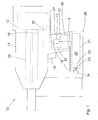
- FIGS. 1 and 2 is an inventive, operable with a liquid or gaseous fuel propellant setting device 10 with a propellant container 20 reproduced.
- the setting device 10 has a housing 11 with a handle 17 integrally formed thereon, on which there is a trigger switch 18, by means of which a setting process can be triggered.
- the setting tool 10 also has a setting network, which includes a combustion chamber 12 for combustion of an air-blowing agent mixture and a set in a piston guide 29 displaceably guided setting piston 19 and via a fastener is driven into a workpiece.
- a propellant container 20 is interchangeably arranged, which is formed in the present embodiment as a gas can and which contains a liquid gas.
- the propellant container 20 has at one end a valve outlet 23 of a valve 22, such. B. a stem, on, can be output via the propellant from the propellant container 20.
- a connection element 14 such in the propellant container receptacle 21, a connection element 14, such.
- the propellant container is then connected via a outgoing from the connection element 14 propellant conduit 15 with the combustion chamber 12, wherein in the propellant conduit 15 is still a metering device 13 is arranged, via which the propellant is influenced to the combustion chamber 12.
- the metering device 13 includes z. B. an electronically controllable valve and may be formed as a fuel injection device.
- an ignition device 16 such as, for. B. a spark plug, arranged, via which a combustion process in the combustion chamber 12 can be triggered.
- the ignition device 16 and the metering device 13 are electronically designated by a total of 30 and in FIG. 2 more precisely controlled control electronics controlled.
- the control electronics 30 has two logic circuits 33, 34 which are logically separate from one another, of which the first circuit 33 controls the metering device 13 and the second circuit 34 controls the ignition device 16.
- the first circuit 33 has a first microprocessor 37 which, on the basis of stored data and measurement data of sensor means 41, 42, which are connected to the first circuit 33, determines the necessary for a setting dose of the blowing agent and transmits the control commands to the metering device 13 ,
- the first circuit 33 is connected to the metering device 13 via a first control line 31.
- a first sensor means 41 serves to detect the ambient temperature
- a second sensor means 42 serves to detect the ambient pressure.
- a first switching means 35 is arranged, the z. B. is designed as a nose switch in the mouth region of the setting device 10. About this switching means 35, the first circuit 33 is independently activated by the second circuit 34, z. B. when the setting tool is pressed against a workpiece or a substrate.
- the second circuit 32 has a second microprocessor 38 which controls the ignition by the ignition device 16. Via a second control line 32, the second circuit 34 is connected to the ignition device 16.
- a second switching means 36 is arranged, the z. B. is coupled to the trigger switch or is formed by the trigger switch itself.
- the second circuit 34 can be activated independently of the first circuit 33, z. B. when the setting device 10 is triggered via the trigger switch 18.
- the second switching means 36 could be switched only indirectly as a result of actuation of the trigger switch 18.
- an energy source 40 such. B. one or more batteries or accumulators, provided, which is connected via leads respectively to the first circuit 33 and the second circuit 34 (see Fig. 2 ). About one Further switching means 39, the power source 40 connected to the circuits 33, 34 and these are supplied with electrical energy.
- the ignition control (34) releases the ignition caused by the discharge of at least one capacitor, the ignition control (34) causes the switch (39) to open, immediately leading to the dosing control (33) being switched off. Ignition is now completed by the energy stored in said capacitor.
Landscapes
- Engineering & Computer Science (AREA)
- Chemical & Material Sciences (AREA)
- Combustion & Propulsion (AREA)
- Mechanical Engineering (AREA)
- Portable Nailing Machines And Staplers (AREA)
Claims (5)
- Appareil de scellement actionné par combustion interne, comprenant une chambre de combustion (12) pour un agent propulseur combustible, comprenant un dispositif d'allumage (16) pour produire une étincelle d'allumage dans la chambre de combustion (12) et un dispositif de dosage (13) pour l'agent propulseur, et comprenant une électronique de commande (30) pour le dispositif d'allumage (16) et pour le dispositif de dosage (13), caractérisé en ce que l'électronique de commande (30) comporte au moins deux circuits de commutation séparés logiquement (33, 34) qui peuvent être séparés électriquement l'un de l'autre et dont un premier circuit de commutation (33) commande le dispositif de dosage (13) et dont un second circuit de commutation (34) commande le dispositif d'allumage (16).
- Appareil de scellement actionné par combustion interne selon la revendication 1, caractérisé en ce qu'au moins un des deux circuits de commutation (33, 34) comporte au moins un microprocesseur (37, 38).
- Appareil de scellement actionné par combustion interne selon la revendication 1 ou 2, caractérisé en ce que le premier circuit de commutation (33) et le second circuit de commutation (34) peuvent chacun être actionnés par l'intermédiaire d'au moins un moyen de commutation (35, 36), les moyens de commutation (35, 36) étant indépendants l'un de l'autre.
- Appareil de scellement actionné par combustion interne selon une des revendications 1 à 3, caractérisé en ce que les deux circuits de commutation (33, 34) sont alimentés en énergie électrique par l'intermédiaire d'une source d'énergie (40).
- Appareil de scellement actionné par combustion interne selon la revendication 4, caractérisé en ce que l'alimentation en énergie par l'intermédiaire de la source d'énergie (40) peut être séparée du premier circuit de commutation (33) et du second circuit de commutation (34) par l'intermédiaire d'un moyen de commutation supplémentaire (39).
Applications Claiming Priority (1)
| Application Number | Priority Date | Filing Date | Title |
|---|---|---|---|
| DE102006000262A DE102006000262B3 (de) | 2006-05-30 | 2006-05-30 | Brennkraftbetriebenes Setzgerät |
Publications (2)
| Publication Number | Publication Date |
|---|---|
| EP1862263A1 EP1862263A1 (fr) | 2007-12-05 |
| EP1862263B1 true EP1862263B1 (fr) | 2009-03-18 |
Family
ID=38442069
Family Applications (1)
| Application Number | Title | Priority Date | Filing Date |
|---|---|---|---|
| EP07108096A Not-in-force EP1862263B1 (fr) | 2006-05-30 | 2007-05-14 | Appareil de scellement à combustion |
Country Status (5)
| Country | Link |
|---|---|
| US (1) | US8261955B2 (fr) |
| EP (1) | EP1862263B1 (fr) |
| JP (1) | JP5189317B2 (fr) |
| DE (2) | DE102006000262B3 (fr) |
| ES (1) | ES2320816T3 (fr) |
Families Citing this family (4)
| Publication number | Priority date | Publication date | Assignee | Title |
|---|---|---|---|---|
| FR2957833B1 (fr) * | 2010-03-23 | 2012-06-01 | Prospection & Inventions | Appareil de fixation a thermistances moteur et cartouche |
| DE102011050580A1 (de) | 2011-05-24 | 2012-11-29 | Fischerwerke Gmbh & Co. Kg | Befestigungselement, Befestigungssystem und Verfahren zum Setzen des Befestigungselements |
| DE102011077832A1 (de) * | 2011-06-20 | 2012-12-20 | Hilti Aktiengesellschaft | Treibmittelbehälter für brennkraftbetriebene Bolzensetzgeräte |
| US12255501B2 (en) | 2022-05-19 | 2025-03-18 | Milwaukee Electric Tool Corporation | Power tool including a printed circuit board with a high impedance trace |
Family Cites Families (9)
| Publication number | Priority date | Publication date | Assignee | Title |
|---|---|---|---|---|
| JPS61171859A (ja) * | 1986-01-09 | 1986-08-02 | Nippon Soken Inc | 内燃機関用電子制御式燃料噴射装置 |
| US5415136A (en) * | 1993-08-30 | 1995-05-16 | Illinois Tool Works Inc. | Combined ignition and fuel system for combustion-powered tool |
| US6123241A (en) * | 1995-05-23 | 2000-09-26 | Applied Tool Development Corporation | Internal combustion powered tool |
| JPH0960540A (ja) * | 1995-08-25 | 1997-03-04 | Yamaha Motor Co Ltd | 内燃機関の制御ユニット |
| US6694959B1 (en) * | 1999-11-19 | 2004-02-24 | Denso Corporation | Ignition and injection control system for internal combustion engine |
| US6983871B2 (en) * | 2002-08-09 | 2006-01-10 | Hitachi Koki Co., Ltd. | Combustion-powered nail gun |
| DE10318554B4 (de) * | 2003-04-24 | 2005-03-24 | Hilti Ag | Brennkraftbetriebenes Setzgerät |
| DE10319647B3 (de) * | 2003-05-02 | 2004-09-02 | Hilti Ag | Setzgerät, Befestigungselemente-Magazin und Treibmittelbehälter |
| DE102004022365A1 (de) * | 2004-05-06 | 2005-12-08 | Hilti Ag | Brennkraftbetriebenes Setzgerät und Treibmittelbehälter für brennkraftbetriebene Setzgeräte |
-
2006
- 2006-05-30 DE DE102006000262A patent/DE102006000262B3/de not_active Expired - Fee Related
-
2007
- 2007-05-14 EP EP07108096A patent/EP1862263B1/fr not_active Not-in-force
- 2007-05-14 DE DE502007000517T patent/DE502007000517D1/de active Active
- 2007-05-14 ES ES07108096T patent/ES2320816T3/es active Active
- 2007-05-29 US US11/807,678 patent/US8261955B2/en not_active Expired - Fee Related
- 2007-05-29 JP JP2007141623A patent/JP5189317B2/ja not_active Expired - Fee Related
Also Published As
| Publication number | Publication date |
|---|---|
| EP1862263A1 (fr) | 2007-12-05 |
| JP2007320028A (ja) | 2007-12-13 |
| US8261955B2 (en) | 2012-09-11 |
| DE502007000517D1 (de) | 2009-04-30 |
| DE102006000262B3 (de) | 2007-10-11 |
| US20070290020A1 (en) | 2007-12-20 |
| ES2320816T3 (es) | 2009-05-28 |
| JP5189317B2 (ja) | 2013-04-24 |
Similar Documents
| Publication | Publication Date | Title |
|---|---|---|
| DE69310093T2 (de) | Brennstoffsystem für ein verbrennungsbetriebenes Befestigungswerkzeug | |
| DE10222338A1 (de) | Brennkraftbetriebenes Setzgerät | |
| DE3129552C2 (fr) | ||
| DE10260702B4 (de) | Brennkraftbetriebenes Setzgerät | |
| DE10318554B4 (de) | Brennkraftbetriebenes Setzgerät | |
| DE19950349A1 (de) | Setzgerät für Befestigungselemente | |
| EP1862263B1 (fr) | Appareil de scellement à combustion | |
| DE2322829A1 (de) | Hand - extrudiervorrichtung | |
| EP1782925B1 (fr) | Outil de scellement entraîné par combustion | |
| EP2090404A2 (fr) | Outil d'entraînement à combustion de gaz | |
| DE2848174C2 (fr) | ||
| DE10260703A1 (de) | Brennkraftbetriebenes Setzgerät | |
| DE2402313A1 (de) | Piezoelektrische brenneranzuender und systeme | |
| DE102004039612A1 (de) | Brennkraftbetriebenes Setzgerät | |
| DE102007024924B4 (de) | Sicherheitsmechanismus für einen Brenner | |
| DE102007046738A1 (de) | Pulversprühbeschichtungsverfahren und -vorrichtung | |
| DE102004022365A1 (de) | Brennkraftbetriebenes Setzgerät und Treibmittelbehälter für brennkraftbetriebene Setzgeräte | |
| DE64017T1 (de) | Bevorratungseinrichtung fuer bewegliche gasheizungsapparate. | |
| EP2922663A1 (fr) | Dispositif de marquage d'une vis ou d'une tête de vis | |
| DE1426371B2 (de) | Vorrichtung zum zuenden oder wiederzuenden von strahltrieb werken | |
| DE102017008756A1 (de) | Handgeführtes Arbeitsgerät mit einem Verbrennungsmotor | |
| DE10244508A1 (de) | Handgeführtes Arbeitsgerät, insbesondere brennkraftbetriebenes Setzgerät | |
| DE102014116585B4 (de) | Spritzvorrichtung und System mit einer Spritzvorrichtung und einer Kartusche | |
| EP2720832A1 (fr) | Récipient d'agent propulseur pour appareil de fixation sous charge propulsive | |
| DE3019777A1 (de) | Schlagapparat |
Legal Events
| Date | Code | Title | Description |
|---|---|---|---|
| PUAI | Public reference made under article 153(3) epc to a published international application that has entered the european phase |
Free format text: ORIGINAL CODE: 0009012 |
|
| AK | Designated contracting states |
Kind code of ref document: A1 Designated state(s): AT BE BG CH CY CZ DE DK EE ES FI FR GB GR HU IE IS IT LI LT LU LV MC MT NL PL PT RO SE SI SK TR |
|
| AX | Request for extension of the european patent |
Extension state: AL BA HR MK YU |
|
| 17P | Request for examination filed |
Effective date: 20080605 |
|
| AKX | Designation fees paid |
Designated state(s): DE ES FR GB |
|
| GRAP | Despatch of communication of intention to grant a patent |
Free format text: ORIGINAL CODE: EPIDOSNIGR1 |
|
| GRAS | Grant fee paid |
Free format text: ORIGINAL CODE: EPIDOSNIGR3 |
|
| GRAA | (expected) grant |
Free format text: ORIGINAL CODE: 0009210 |
|
| AK | Designated contracting states |
Kind code of ref document: B1 Designated state(s): DE ES FR GB |
|
| REG | Reference to a national code |
Ref country code: GB Ref legal event code: FG4D Free format text: NOT ENGLISH |
|
| REF | Corresponds to: |
Ref document number: 502007000517 Country of ref document: DE Date of ref document: 20090430 Kind code of ref document: P |
|
| REG | Reference to a national code |
Ref country code: ES Ref legal event code: FG2A Ref document number: 2320816 Country of ref document: ES Kind code of ref document: T3 |
|
| PLBE | No opposition filed within time limit |
Free format text: ORIGINAL CODE: 0009261 |
|
| STAA | Information on the status of an ep patent application or granted ep patent |
Free format text: STATUS: NO OPPOSITION FILED WITHIN TIME LIMIT |
|
| 26N | No opposition filed |
Effective date: 20091221 |
|
| REG | Reference to a national code |
Ref country code: FR Ref legal event code: PLFP Year of fee payment: 10 |
|
| REG | Reference to a national code |
Ref country code: FR Ref legal event code: PLFP Year of fee payment: 11 |
|
| REG | Reference to a national code |
Ref country code: FR Ref legal event code: PLFP Year of fee payment: 12 |
|
| PGFP | Annual fee paid to national office [announced via postgrant information from national office to epo] |
Ref country code: GB Payment date: 20220519 Year of fee payment: 16 Ref country code: FR Payment date: 20220523 Year of fee payment: 16 Ref country code: DE Payment date: 20220519 Year of fee payment: 16 |
|
| PGFP | Annual fee paid to national office [announced via postgrant information from national office to epo] |
Ref country code: ES Payment date: 20220725 Year of fee payment: 16 |
|
| REG | Reference to a national code |
Ref country code: DE Ref legal event code: R119 Ref document number: 502007000517 Country of ref document: DE |
|
| GBPC | Gb: european patent ceased through non-payment of renewal fee |
Effective date: 20230514 |
|
| PG25 | Lapsed in a contracting state [announced via postgrant information from national office to epo] |
Ref country code: DE Free format text: LAPSE BECAUSE OF NON-PAYMENT OF DUE FEES Effective date: 20231201 Ref country code: GB Free format text: LAPSE BECAUSE OF NON-PAYMENT OF DUE FEES Effective date: 20230514 |
|
| PG25 | Lapsed in a contracting state [announced via postgrant information from national office to epo] |
Ref country code: FR Free format text: LAPSE BECAUSE OF NON-PAYMENT OF DUE FEES Effective date: 20230531 |
|
| REG | Reference to a national code |
Ref country code: ES Ref legal event code: FD2A Effective date: 20240628 |
|
| PG25 | Lapsed in a contracting state [announced via postgrant information from national office to epo] |
Ref country code: ES Free format text: LAPSE BECAUSE OF NON-PAYMENT OF DUE FEES Effective date: 20230515 |
|
| PG25 | Lapsed in a contracting state [announced via postgrant information from national office to epo] |
Ref country code: ES Free format text: LAPSE BECAUSE OF NON-PAYMENT OF DUE FEES Effective date: 20230515 |