EP1862352A2 - Appui-tête pour véhicule automobile - Google Patents
Appui-tête pour véhicule automobile Download PDFInfo
- Publication number
- EP1862352A2 EP1862352A2 EP20070005642 EP07005642A EP1862352A2 EP 1862352 A2 EP1862352 A2 EP 1862352A2 EP 20070005642 EP20070005642 EP 20070005642 EP 07005642 A EP07005642 A EP 07005642A EP 1862352 A2 EP1862352 A2 EP 1862352A2
- Authority
- EP
- European Patent Office
- Prior art keywords
- locking
- locking element
- headrest according
- headrest
- support
- Prior art date
- Legal status (The legal status is an assumption and is not a legal conclusion. Google has not performed a legal analysis and makes no representation as to the accuracy of the status listed.)
- Granted
Links
Images


Classifications
-
- B—PERFORMING OPERATIONS; TRANSPORTING
- B60—VEHICLES IN GENERAL
- B60N—SEATS SPECIALLY ADAPTED FOR VEHICLES; VEHICLE PASSENGER ACCOMMODATION NOT OTHERWISE PROVIDED FOR
- B60N2/00—Seats specially adapted for vehicles; Arrangement or mounting of seats in vehicles
- B60N2/80—Head-rests
- B60N2/806—Head-rests movable or adjustable
- B60N2/838—Tiltable
- B60N2/856—Tiltable movable to an inoperative or stowed position
Definitions
- Such a headrest is known from the DE 102 36 259 A1 ,
- the known headrest has a cushion support, which is held about a pivot axis pivotally mounted on support rods which are fixed to the backrest.
- the cushion support may be pivoted between a use position and a non-use position, wherein the cushion body in the use position provides a bearing surface for the head of a vehicle occupant.
- the headrest is locked in the use position. Unlocking is possible by a locking element can be translationally transferred from the locking position into the release position by pressure on an actuating slide, wherein in the release position, a pivoting of the cushion support is possible.
- a headrest wherein the cushion support is pivotally mounted on a support bar bracket and is lockable in a use and a non-use position.
- a locking pin is mounted translationally displaceable.
- the locking pin has an end portion on an end portion which cooperates with recesses of a locking plate attached to the locking disc.
- the principle of the invention consists essentially in the fact that a locking element pivotable about a pivot axis is arranged on the cushion support. In the locking position, the locking element cooperates with a retaining element fastened to the support rod such that pivoting of the cushion support is not possible. By pivoting the locking element in the release position, the locking element and the retaining element are disengaged, so that a pivoting of the cushion support is made possible.
- “Locking device” within the meaning of the invention is a device with which the cushion support is detachably lockable at least in the use position.
- the cushion support is releasably lockable both in the use and in the non-use position and possibly also in intermediate positions.
- the advantage of the invention is that it is possible for the locking element to be designed such that the center of gravity is located on or in the vicinity of the axis of rotation. In a vehicle crash, it can not in this way by inertial forces to an unwanted movement of the locking element in the release position and so come to a pivoting of the cushion support.
- the headrest according to the invention provides high security, because by means of the pivotable locking element high holding forces can be transmitted. Due to the simple structure, the headrest has a high reliability.
- actuation travel and actuation force are inversely proportional to each other.
- actuation travel and actuation force are inversely proportional to each other.
- a lower actuation force is required, e.g. to actuate a loaded by a spring pivot bolt.
- the required at a certain distance from the pivot axis actuating path for pivoting the rotary latch is the lower, the closer the actuation takes place on the axis of rotation.
- the center of gravity of the locking element is arranged on or in the vicinity of the axis of rotation.
- this embodiment prevents unintentional pivoting of the locking element. In this way, it is not necessary to pivot the locking element e.g. by springs with high spring forces to prevent.
- the locking element is formed by a disc.
- the disk may be formed for example by a sheet-metal stamped part. To this Way, the locking element is easy to produce. By means of the outer surfaces of the disk, large holding forces can be transmitted.
- the disc takes only a small space within the cushion support.
- the disc can also be designed such that it has a low weight.
- the locking element is formed substantially circular.
- a circular disc forms a large outer surface to which holding forces are transmitted and actuators and a return spring can attack.
- the retaining element has at least one stop surface, which cooperates in the locking position with at least one outer surface region of the locking element.
- the stop surface by a large configuration of the stop surface, large holding forces can be transmitted.
- the retaining element has at least one recess, wherein at least one inner surface of the recess forms the abutment surface for the locking element.
- the locking element In the locking position, the locking element is thus arranged within the recess.
- the abutment surface of the retaining element and the counter surface of the locking element cooperate arresting.
- the locking element has recesses adjacent the outer surface area. By locating the recesses adjacent the outer surface portion, the latch member need only be slightly pivoted to move it between the latch and release positions. The actuators can then be designed so that they have only small adjustment paths.
- the locking element has at least one operating region, which cooperates with an actuating element for pivoting the locking element.
- the actuating region may be formed, for example, by a surface which is in contact with the actuating element and via which a power transmission to the locking element is possible.
- the actuating element is formed by an electromagnetically actuated plunger.
- the actuating element is formed by a translationally actuated slide.
- the slide may, for example, be actuated against the force of a spring element and exert a force on the actuating region, which has a pivoting of the locking element result.
- a spring element is assigned to the locking element, wherein the locking element is movable against the force of the spring element from the locking position into the release position.
- the locking element is held in this way by the spring element in the locking position and is pivotable against the force of the spring element in the release position.
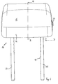
- a headrest as a whole is denoted by the reference numeral 10 in the drawings.
- Like reference numerals in the different figures indicate corresponding parts.
- the headrest 10 has, according to FIG. 1, a support bar bracket 13 with free support rod ends 11.
- the free support rod ends 11 are held in a manner not shown on the backrest of a vehicle seat.
- a cushion support 14 is mounted on the support bar bracket 13, a cushion support 14 is mounted.
- a contact surface 15 serves as a support surface for the head of a vehicle occupant, not shown.
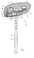
- the cushion support 14 can be pivoted from the use position shown in Fig. 1 to a non-use position shown in Fig. 2, e.g. to allow the driver a better view from the rear window when no passenger is on a rear seat of the vehicle.
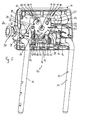
- the headrest 10 In order to prevent a reversed pivoting of the cushion support 14, the headrest 10 according to FIG. 3 has a locking device 16, which comprises a disc-shaped rotary latch 17 and a holding element 18, which is welded onto a transverse web 12 of the support bar bracket 13.
- the cross bar 12 forms a pivot axis b for the cushion body 14.
- the rotary latch 17 In Fig. 3, the rotary latch 17 is shown in a locking position, which is explained below with reference to FIG. 5.
- the rotary latch 17 is rotatably mounted about an axis A on a stub axle 19 which is fixed to a mounting plate 20.
- the mounting plate 20 is fixed in a manner not shown on the cushion support 14.
- rotary latch sections 21 pass through recesses 22 of arms 23 of the bracket-shaped retaining element 18.
- outer surfaces 24 of the rotary latch sections 21 form abutment surfaces which cooperate with mating surfaces 25 which are formed by inner surfaces of the recesses 22.
- the padding support can therefore be pivoted neither in the pivoting direction v1 nor in the pivoting direction v2 (see FIG. 3).
- the cushion support 14 is pivoted in the release position of the rotary latch 17 by a spring element 35 from the use position shown in FIG. 3 to the rear in the non-use position shown in FIG.
- a spring element 35 from the use position shown in FIG. 3 to the rear in the non-use position shown in FIG.
- umzuschwenken the cushion support in the direction v2 forward it would also be conceivable according to another embodiment, not shown, umzuschwenken the cushion support in the direction v2 forward.
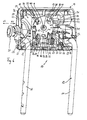
- the rotary latch 17 is loaded by a spring element 41 in the pivoting direction u1. After a pivoting of the cushion support 14 against the spring force of the spring element 35 from the non-use position shown in FIG. 4 in the use position of the rotary latch 17 is therefore pivoted in the use position of the cushion support 14 of FIG. 5 of the spring element 41 in the direction u1 in the above-described locking position ,
- the rotary latch 17 In order to enable a transmission of large forces, as they act in the event of a crash on the cushion body 14, the rotary latch 17 with respect to the axis of rotation a radially outwardly arranged slots 38, which are penetrated by pins 39.
- the pins 29 are mounted in a manner not shown on the cushion support 14 and have at their free end thickenings 40 which hold the rotary latch 17 even at high loads firmly in the position shown in Fig. 5.
- the slots 38 allow the pivoting of the rotary latch 17 between the locking position and the release position.
- the pins e.g.
- the moldings could e.g. Have sliding surfaces which cooperate with the outer surface of the rotary latch 17.
- the rotary latch 17 In order to pivot the rotary latch 17 in the direction u2 in the release position, the rotary latch 17 has an actuating portion 27 and a further operating portion 28.
- the actuating portion 27 has a sliding surface 42 which cooperates with a plunger 30 of an electromagnet 31.
- the plunger 30 is therefore not firmly connected to the actuating portion 27, but can slide along the sliding surface 42.
- the rotary latch 17 By moving the plunger 30 in the direction x2 of FIG. 5, the rotary latch 17 is moved against the force of the spring element 41 in the direction u2 in the release position.
- the cushion support 14 is then pivoted in the manner described above by the spring element 35 in the non-use position.
- the electromagnet 31 can be actuated, for example, from the dashboard, so that the cushion support 14 of a rear vehicle seat can also be pivoted by the driver into the non-use position.
- the rotary latch 17 can also be manually pivoted into the release position.
- the operating section 28 of the rotary latch 17 has a sliding surface 32 which cooperates with the end face 33 of a slide 34.
- the slider 34 is not fixedly connected to the operating portion 28.
- the end face 33 can slide along the sliding surface 32.
- the slider 34 is movable against the force of a spring element, not shown, from the position according to FIG. 5 in the direction x1, wherein the end face 33 exerts a force on the sliding surface 32 of the rotary latch 17 and the rotary latch 17 is thereby pivoted in the direction u2 in the release position , With decreasing pressure on the slider 34 it is moved by the spring element, not shown in the direction x2.
Landscapes
- Engineering & Computer Science (AREA)
- Aviation & Aerospace Engineering (AREA)
- Transportation (AREA)
- Mechanical Engineering (AREA)
- Seats For Vehicles (AREA)
- Chair Legs, Seat Parts, And Backrests (AREA)
Applications Claiming Priority (2)
| Application Number | Priority Date | Filing Date | Title |
|---|---|---|---|
| DE102006025741 | 2006-05-31 | ||
| DE102006027646A DE102006027646C5 (de) | 2006-05-31 | 2006-06-13 | Kopfstütze für Fahrzeuge |
Publications (3)
| Publication Number | Publication Date |
|---|---|
| EP1862352A2 true EP1862352A2 (fr) | 2007-12-05 |
| EP1862352A3 EP1862352A3 (fr) | 2009-04-15 |
| EP1862352B1 EP1862352B1 (fr) | 2015-11-04 |
Family
ID=38544170
Family Applications (1)
| Application Number | Title | Priority Date | Filing Date |
|---|---|---|---|
| EP07005642.9A Active EP1862352B1 (fr) | 2006-05-31 | 2007-03-20 | Appui-tête pour véhicule automobile |
Country Status (4)
| Country | Link |
|---|---|
| US (1) | US8066330B2 (fr) |
| EP (1) | EP1862352B1 (fr) |
| CN (1) | CN101081606B (fr) |
| DE (1) | DE102006027646C5 (fr) |
Cited By (3)
| Publication number | Priority date | Publication date | Assignee | Title |
|---|---|---|---|---|
| CN104071051A (zh) * | 2013-03-14 | 2014-10-01 | 温泽机械和制模2009有限责任公司 | 具有电磁闭锁释放机构的车辆头部约束件 |
| DE102017009580A1 (de) | 2017-10-13 | 2019-04-18 | Grammer Ag | Kopfstütze |
| DE102018104072A1 (de) | 2018-02-22 | 2019-08-22 | Grammer Aktiengesellschaft | Tragstangenbügel sowie Kopfstütze mit Tragstangenbügel |
Families Citing this family (27)
| Publication number | Priority date | Publication date | Assignee | Title |
|---|---|---|---|---|
| US7669932B1 (en) * | 2006-02-28 | 2010-03-02 | Grammer A.G. | Headrest |
| JP5083793B2 (ja) * | 2006-05-02 | 2012-11-28 | テイ・エス テック株式会社 | 車両用シートのヘッドレスト |
| US20080203801A1 (en) * | 2007-02-28 | 2008-08-28 | Lear Corporation | Folding head restraint mechanism |
| JP5057823B2 (ja) * | 2007-03-31 | 2012-10-24 | テイ・エス テック株式会社 | ヘッドレスト及び該ヘッドレストを備えた車両用シート |
| DE102008048313B3 (de) * | 2008-09-22 | 2010-03-04 | Lear Corp., Southfield | Einstellbare Fahrzeug-Kopfstützeneinrichtung für einen Fahrzeugsitz |
| US8126617B2 (en) * | 2009-01-12 | 2012-02-28 | Lear Corporation | Folding head restraint assembly for convertible vehicle |
| GB2469310B (en) * | 2009-04-08 | 2013-11-06 | Ford Global Tech Llc | A seat having an armrest assembly |
| US20100283305A1 (en) * | 2009-05-06 | 2010-11-11 | Lear Corporation | Folding vehicle head restraint assembly |
| US8348347B2 (en) * | 2009-05-06 | 2013-01-08 | Lear Corporation | Folding vehicle head restraint assembly |
| US8851574B2 (en) | 2009-05-06 | 2014-10-07 | Lear Corporation | Folding vehicle head restraint assembly |
| DE102009020117B4 (de) * | 2009-05-06 | 2013-11-14 | Lear Corp. | Sitzanordnung und verstellbare Kopfstützenanordnung |
| US8246116B1 (en) * | 2009-08-24 | 2012-08-21 | Sutter Jr Robert R | Head restraint assembly with sliding latch |
| US8807653B2 (en) | 2010-09-17 | 2014-08-19 | Lear Corporation | Adjustable head restraint assembly for vehicle seats |
| DE102010041941A1 (de) | 2010-10-04 | 2012-04-05 | Lear Corporation | Bewegliche Kopfstützen für Fahrzeugsitze |
| US8465098B2 (en) | 2011-06-21 | 2013-06-18 | Lear Corporation | Adjustable head restraint assembly for vehicle seats |
| US8820839B1 (en) * | 2012-04-24 | 2014-09-02 | Gill Industries, Inc. | Head restraint assembly |
| CN102649405B (zh) * | 2012-05-17 | 2013-10-30 | 上海岱美汽车内饰件股份有限公司 | 一种带按钮能t型向后折叠的汽车座椅头枕 |
| US9061615B2 (en) * | 2012-12-13 | 2015-06-23 | Daimay North America Automotive, Inc. | Folding headrest |
| DE102014001980B3 (de) * | 2014-02-17 | 2015-04-23 | Grammer Ag | Kopfstütze für Fahrzeugsitze |
| JP6431347B2 (ja) * | 2014-11-26 | 2018-11-28 | 株式会社タチエス | アームレスト付きシート及びそれに用いるアームレストのロック解除装置 |
| WO2017022250A1 (fr) * | 2015-08-04 | 2017-02-09 | テイ・エス テック株式会社 | Dispositif de support d'appui-tête |
| DE102015012411B4 (de) * | 2015-09-25 | 2022-06-09 | Grammer Aktiengesellschaft | Kopfstütze |
| CN106696779B (zh) * | 2015-11-13 | 2019-06-11 | 奥迪股份公司 | 用于机动车辆的安全装置 |
| US11117504B2 (en) * | 2017-06-29 | 2021-09-14 | Tesca France | Headrest for a motor vehicle seat |
| US20190168650A1 (en) * | 2017-12-01 | 2019-06-06 | Windsor Machine and Stamping (2009) Ltd. | Foldable head restraint |
| WO2019174037A1 (fr) | 2018-03-16 | 2019-09-19 | Daimay North America Automotive, Inc. | Ensemble appui-tête à cliquet |
| FR3135029A1 (fr) | 2022-04-29 | 2023-11-03 | Faurecia Sièges d'Automobile | Système support pour appui-tête de siège automobile |
Citations (2)
| Publication number | Priority date | Publication date | Assignee | Title |
|---|---|---|---|---|
| DE20207115U1 (de) | 2002-05-04 | 2002-08-29 | Faurecia Autositze GmbH & Co. KG, 31655 Stadthagen | Rückenlehne eines Kraftfahrzeugs mit Kopfstütze |
| US20050242640A1 (en) | 2004-04-15 | 2005-11-03 | Barko Jerry S | Folding headrest assembly |
Family Cites Families (12)
| Publication number | Priority date | Publication date | Assignee | Title |
|---|---|---|---|---|
| JPS5744990Y2 (fr) * | 1979-02-14 | 1982-10-04 | ||
| DE3625691A1 (de) * | 1986-07-30 | 1988-02-04 | Fhs Stahlverformung Gmbh | Hoehen- und neigungsverstellbare kopfstuetze mit mittlerem fenster fuer kraftfahrzeugsitze |
| DE8626167U1 (de) * | 1986-10-01 | 1986-12-18 | Adam Opel AG, 6090 Rüsselsheim | Verriegelungsvorrichtung für eine Hintersitz-Rückenlehne |
| KR19980024703U (ko) * | 1996-10-31 | 1998-07-25 | 정해일 | 자동차용 헤드레스트의 틸팅장치 |
| US5826942A (en) * | 1997-01-23 | 1998-10-27 | Hoover Universal, Inc. | Vehicle seat assembly with adjustable headrest coupled to seat back latch |
| DE19835355C1 (de) * | 1998-08-05 | 1999-12-02 | Daimler Chrysler Ag | Kopfstütze |
| JP4280950B2 (ja) * | 1999-08-09 | 2009-06-17 | アイシン精機株式会社 | ヘッドレスト装置 |
| SE520924C2 (sv) * | 2002-01-07 | 2003-09-16 | Kongsberg Automotive Ab | Nackskydd för motorfordon |
| DE10236259B4 (de) * | 2002-08-07 | 2006-02-23 | Grammer Ag | Kopfstütze für Fahrzeugsitze |
| DE10256642B3 (de) * | 2002-12-03 | 2004-06-09 | Keiper Gmbh & Co. Kg | Kopfstütze |
| DE10355773B3 (de) * | 2003-11-26 | 2005-01-20 | Grammer Ag | Kopfstütze für Kraftfahrzeugsitze |
| DE202004004251U1 (de) * | 2004-03-18 | 2005-05-04 | Brose Fahrzeugteile Gmbh & Co. Kommanditgesellschaft, Coburg | Kopfstütze für einen Kraftfahrzeugsitz |
-
2006
- 2006-06-13 DE DE102006027646A patent/DE102006027646C5/de not_active Expired - Fee Related
-
2007
- 2007-03-20 EP EP07005642.9A patent/EP1862352B1/fr active Active
- 2007-05-15 CN CN2007101032885A patent/CN101081606B/zh active Active
- 2007-05-30 US US11/807,904 patent/US8066330B2/en not_active Expired - Fee Related
Patent Citations (2)
| Publication number | Priority date | Publication date | Assignee | Title |
|---|---|---|---|---|
| DE20207115U1 (de) | 2002-05-04 | 2002-08-29 | Faurecia Autositze GmbH & Co. KG, 31655 Stadthagen | Rückenlehne eines Kraftfahrzeugs mit Kopfstütze |
| US20050242640A1 (en) | 2004-04-15 | 2005-11-03 | Barko Jerry S | Folding headrest assembly |
Cited By (5)
| Publication number | Priority date | Publication date | Assignee | Title |
|---|---|---|---|---|
| CN104071051A (zh) * | 2013-03-14 | 2014-10-01 | 温泽机械和制模2009有限责任公司 | 具有电磁闭锁释放机构的车辆头部约束件 |
| DE102017009580A1 (de) | 2017-10-13 | 2019-04-18 | Grammer Ag | Kopfstütze |
| DE102017009580B4 (de) | 2017-10-13 | 2022-09-08 | Grammer Aktiengesellschaft | Kopfstütze für einen Sitz |
| DE102018104072A1 (de) | 2018-02-22 | 2019-08-22 | Grammer Aktiengesellschaft | Tragstangenbügel sowie Kopfstütze mit Tragstangenbügel |
| DE102018104072B4 (de) | 2018-02-22 | 2023-04-20 | Grammer Aktiengesellschaft | Tragstangenbügel sowie Kopfstütze mit Tragstangenbügel |
Also Published As
| Publication number | Publication date |
|---|---|
| DE102006027646A1 (de) | 2007-12-06 |
| US20070284929A1 (en) | 2007-12-13 |
| CN101081606A (zh) | 2007-12-05 |
| EP1862352A3 (fr) | 2009-04-15 |
| DE102006027646C5 (de) | 2010-10-14 |
| US8066330B2 (en) | 2011-11-29 |
| EP1862352B1 (fr) | 2015-11-04 |
| CN101081606B (zh) | 2011-02-02 |
| DE102006027646B4 (de) | 2009-01-15 |
Similar Documents
| Publication | Publication Date | Title |
|---|---|---|
| EP1862352B1 (fr) | Appui-tête pour véhicule automobile | |
| DE102007025327B4 (de) | Fahrzeugsitzanordnung | |
| EP1193114A1 (fr) | Appui-tête | |
| EP2608988B1 (fr) | Dispositif de blocage d'un appui-tête | |
| DE102004017688A1 (de) | Kopfstütze für Automobilsitze | |
| DE102011004396B4 (de) | Einziehbare Kopfstütze | |
| EP3299216B1 (fr) | Accoudoir | |
| DE4417491C2 (de) | Fanghaken zur lösbaren Verriegelung der mit dem Sitzteil eines Fahrzeugsitzes vorschwenkbar verbundenen Rückenlehne | |
| DE102011116709A1 (de) | Verriegelungs- und Neigungsverstellanordnung, insbesondere Lehnenschloss | |
| DE102013207927A1 (de) | Mittelarmlehne mit Crashsicherung | |
| DE69700556T2 (de) | Nach vorn bewegbarer Fahrzeugsitz, um zu einem hinteren Raum zu gelangen | |
| DE102015012411B4 (de) | Kopfstütze | |
| DE112013006427T5 (de) | Einklappbarer Kopfstützenaufbau | |
| DE2514819A1 (de) | Fahrzeug- insbesondere kraftwagensitz | |
| DE102014001980B3 (de) | Kopfstütze für Fahrzeugsitze | |
| EP3694744B1 (fr) | Siege de vehicule avec mechanisme easy-entry | |
| DE102008011560B3 (de) | Verriegelungsvorrichtung, insbesondere für eine Kopfstütze für Fahrzeugsitze | |
| DE10145240A1 (de) | Kopfstütze für Fahrzeugsitze | |
| DE102017009580B4 (de) | Kopfstütze für einen Sitz | |
| EP1604863B1 (fr) | Dispositif pour maintenir le dossier d'un siège de véhicule automobile | |
| DE102007006768A1 (de) | Überrollschutzsystem für Kraftfahrzeuge mit einem sensorgesteuert aktiv aufstellbaren Überrollkörper | |
| EP3908480B1 (fr) | Mécanisme de réglage et appui-tête | |
| DE102007043065A1 (de) | Kopfstütze für Fahrzeugsitze | |
| DE102005005826B4 (de) | Kopfstütze | |
| WO2021048328A1 (fr) | Siège de véhicule ayant un ensemble de verrouillage |
Legal Events
| Date | Code | Title | Description |
|---|---|---|---|
| PUAI | Public reference made under article 153(3) epc to a published international application that has entered the european phase |
Free format text: ORIGINAL CODE: 0009012 |
|
| AK | Designated contracting states |
Kind code of ref document: A2 Designated state(s): AT BE BG CH CY CZ DE DK EE ES FI FR GB GR HU IE IS IT LI LT LU LV MC MT NL PL PT RO SE SI SK TR |
|
| AX | Request for extension of the european patent |
Extension state: AL BA HR MK YU |
|
| PUAL | Search report despatched |
Free format text: ORIGINAL CODE: 0009013 |
|
| AK | Designated contracting states |
Kind code of ref document: A3 Designated state(s): AT BE BG CH CY CZ DE DK EE ES FI FR GB GR HU IE IS IT LI LT LU LV MC MT NL PL PT RO SE SI SK TR |
|
| AX | Request for extension of the european patent |
Extension state: AL BA HR MK RS |
|
| 17P | Request for examination filed |
Effective date: 20090709 |
|
| 17Q | First examination report despatched |
Effective date: 20090824 |
|
| AKX | Designation fees paid |
Designated state(s): DE ES FR GB IT SE |
|
| GRAP | Despatch of communication of intention to grant a patent |
Free format text: ORIGINAL CODE: EPIDOSNIGR1 |
|
| INTG | Intention to grant announced |
Effective date: 20150622 |
|
| GRAS | Grant fee paid |
Free format text: ORIGINAL CODE: EPIDOSNIGR3 |
|
| GRAA | (expected) grant |
Free format text: ORIGINAL CODE: 0009210 |
|
| AK | Designated contracting states |
Kind code of ref document: B1 Designated state(s): DE ES FR GB IT SE |
|
| REG | Reference to a national code |
Ref country code: GB Ref legal event code: FG4D Free format text: NOT ENGLISH |
|
| REG | Reference to a national code |
Ref country code: DE Ref legal event code: R096 Ref document number: 502007014362 Country of ref document: DE |
|
| REG | Reference to a national code |
Ref country code: SE Ref legal event code: TRGR |
|
| REG | Reference to a national code |
Ref country code: FR Ref legal event code: PLFP Year of fee payment: 10 |
|
| PG25 | Lapsed in a contracting state [announced via postgrant information from national office to epo] |
Ref country code: ES Free format text: LAPSE BECAUSE OF FAILURE TO SUBMIT A TRANSLATION OF THE DESCRIPTION OR TO PAY THE FEE WITHIN THE PRESCRIBED TIME-LIMIT Effective date: 20151104 |
|
| REG | Reference to a national code |
Ref country code: DE Ref legal event code: R097 Ref document number: 502007014362 Country of ref document: DE |
|
| PLBE | No opposition filed within time limit |
Free format text: ORIGINAL CODE: 0009261 |
|
| STAA | Information on the status of an ep patent application or granted ep patent |
Free format text: STATUS: NO OPPOSITION FILED WITHIN TIME LIMIT |
|
| 26N | No opposition filed |
Effective date: 20160805 |
|
| GBPC | Gb: european patent ceased through non-payment of renewal fee |
Effective date: 20160320 |
|
| PG25 | Lapsed in a contracting state [announced via postgrant information from national office to epo] |
Ref country code: GB Free format text: LAPSE BECAUSE OF NON-PAYMENT OF DUE FEES Effective date: 20160320 |
|
| REG | Reference to a national code |
Ref country code: FR Ref legal event code: PLFP Year of fee payment: 11 |
|
| REG | Reference to a national code |
Ref country code: DE Ref legal event code: R079 Ref document number: 502007014362 Country of ref document: DE Free format text: PREVIOUS MAIN CLASS: B60N0002480000 Ipc: B60N0002800000 |
|
| REG | Reference to a national code |
Ref country code: FR Ref legal event code: PLFP Year of fee payment: 12 |
|
| REG | Reference to a national code |
Ref country code: DE Ref legal event code: R082 Ref document number: 502007014362 Country of ref document: DE Representative=s name: PATENTANWAELTE ROCHE, VON WESTERNHAGEN & EHRES, DE Ref country code: DE Ref legal event code: R081 Ref document number: 502007014362 Country of ref document: DE Owner name: GRAMMER AKTIENGESELLSCHAFT, DE Free format text: FORMER OWNER: GRAMMER AKTIENGESELLSCHAFT, 92224 AMBERG, DE |
|
| PGFP | Annual fee paid to national office [announced via postgrant information from national office to epo] |
Ref country code: FR Payment date: 20230320 Year of fee payment: 17 |
|
| PGFP | Annual fee paid to national office [announced via postgrant information from national office to epo] |
Ref country code: SE Payment date: 20230315 Year of fee payment: 17 |
|
| P01 | Opt-out of the competence of the unified patent court (upc) registered |
Effective date: 20230530 |
|
| PGFP | Annual fee paid to national office [announced via postgrant information from national office to epo] |
Ref country code: IT Payment date: 20230331 Year of fee payment: 17 |
|
| REG | Reference to a national code |
Ref country code: SE Ref legal event code: EUG |
|
| PG25 | Lapsed in a contracting state [announced via postgrant information from national office to epo] |
Ref country code: FR Free format text: LAPSE BECAUSE OF NON-PAYMENT OF DUE FEES Effective date: 20240331 |
|
| PG25 | Lapsed in a contracting state [announced via postgrant information from national office to epo] |
Ref country code: FR Free format text: LAPSE BECAUSE OF NON-PAYMENT OF DUE FEES Effective date: 20240331 |
|
| PG25 | Lapsed in a contracting state [announced via postgrant information from national office to epo] |
Ref country code: IT Free format text: LAPSE BECAUSE OF NON-PAYMENT OF DUE FEES Effective date: 20240320 |
|
| PG25 | Lapsed in a contracting state [announced via postgrant information from national office to epo] |
Ref country code: SE Free format text: LAPSE BECAUSE OF NON-PAYMENT OF DUE FEES Effective date: 20240321 |
|
| PGFP | Annual fee paid to national office [announced via postgrant information from national office to epo] |
Ref country code: DE Payment date: 20260320 Year of fee payment: 20 |