EP1862375A2 - Einparkhilfsverfahren und Einparkhilfsvorrichtung - Google Patents
Einparkhilfsverfahren und Einparkhilfsvorrichtung Download PDFInfo
- Publication number
- EP1862375A2 EP1862375A2 EP07009506A EP07009506A EP1862375A2 EP 1862375 A2 EP1862375 A2 EP 1862375A2 EP 07009506 A EP07009506 A EP 07009506A EP 07009506 A EP07009506 A EP 07009506A EP 1862375 A2 EP1862375 A2 EP 1862375A2
- Authority
- EP
- European Patent Office
- Prior art keywords
- vehicle
- image
- line
- parking assist
- straight
- Prior art date
- Legal status (The legal status is an assumption and is not a legal conclusion. Google has not performed a legal analysis and makes no representation as to the accuracy of the status listed.)
- Granted
Links
- 238000000034 method Methods 0.000 title claims description 13
- 240000004050 Pentaglottis sempervirens Species 0.000 claims abstract description 70
- 235000004522 Pentaglottis sempervirens Nutrition 0.000 claims abstract description 70
- 230000002093 peripheral effect Effects 0.000 claims description 21
- 238000009877 rendering Methods 0.000 claims description 20
- 238000003384 imaging method Methods 0.000 claims description 13
- 238000001454 recorded image Methods 0.000 claims description 12
- 230000002194 synthesizing effect Effects 0.000 claims description 3
- 238000013500 data storage Methods 0.000 claims description 2
- 238000009434 installation Methods 0.000 claims 1
- 230000004913 activation Effects 0.000 description 14
- 238000006243 chemical reaction Methods 0.000 description 11
- 230000014509 gene expression Effects 0.000 description 11
- 238000000605 extraction Methods 0.000 description 8
- 238000009825 accumulation Methods 0.000 description 5
- 230000015572 biosynthetic process Effects 0.000 description 4
- 238000001514 detection method Methods 0.000 description 4
- 238000003786 synthesis reaction Methods 0.000 description 4
- 238000007726 management method Methods 0.000 description 3
- 238000004364 calculation method Methods 0.000 description 2
- 238000010586 diagram Methods 0.000 description 2
- 230000000694 effects Effects 0.000 description 2
- 230000007935 neutral effect Effects 0.000 description 2
- 230000003287 optical effect Effects 0.000 description 2
- 238000013459 approach Methods 0.000 description 1
- 238000003708 edge detection Methods 0.000 description 1
- 239000000284 extract Substances 0.000 description 1
- 239000000203 mixture Substances 0.000 description 1
- 238000001308 synthesis method Methods 0.000 description 1
- 230000000007 visual effect Effects 0.000 description 1
Images








Classifications
-
- B—PERFORMING OPERATIONS; TRANSPORTING
- B62—LAND VEHICLES FOR TRAVELLING OTHERWISE THAN ON RAILS
- B62D—MOTOR VEHICLES; TRAILERS
- B62D15/00—Steering not otherwise provided for
- B62D15/02—Steering position indicators ; Steering position determination; Steering aids
- B62D15/027—Parking aids, e.g. instruction means
- B62D15/0275—Parking aids, e.g. instruction means by overlaying a vehicle path based on present steering angle over an image without processing that image
-
- B—PERFORMING OPERATIONS; TRANSPORTING
- B62—LAND VEHICLES FOR TRAVELLING OTHERWISE THAN ON RAILS
- B62D—MOTOR VEHICLES; TRAILERS
- B62D15/00—Steering not otherwise provided for
- B62D15/02—Steering position indicators ; Steering position determination; Steering aids
- B62D15/027—Parking aids, e.g. instruction means
- B62D15/028—Guided parking by providing commands to the driver, e.g. acoustically or optically
-
- G—PHYSICS
- G08—SIGNALLING
- G08G—TRAFFIC CONTROL SYSTEMS
- G08G1/00—Traffic control systems for road vehicles
- G08G1/16—Anti-collision systems
- G08G1/168—Driving aids for parking, e.g. acoustic or visual feedback on parking space
Definitions
- the present invention relates to a parking assist method and a parking assist device.
- An on-board device for displaying images captured by an on-board camera on a display is known in the related art. This device inputs an image signal from an on-board camera attached to the rear end of a vehicle, and outputs a peripheral image based on the image signal together with guide lines to a display disposed near the driving seat.
- JP-A-2002-373327 describes an image processing device that accumulates image data input from an on-board camera during a parking operation, performs image processing using the accumulated image data, and displays a bird's-eye view image of the peripheral area of the vehicle.
- JP-A-2004-114879 proposes a device which not only displays a bird's-eye view image, but also superposes a predicted route corresponding to the steering angle at the current point in time and a target route to a parking frame on the bird's-eye view image.
- the resulting image serves favorably as a guidepost for a steering wheel operation or the like, but only the deviation between the route that would be taken were the vehicle to reverse (or advance) at the current steering angle and a target parking area 73 can be learned from the image, and it is impossible to determine a specific steering wheel operation. In other words, insufficient information relating to the driving operation to be performed during parking is provided, and therefore the driver must perform repeated small adjustments of the steering angle. Meanwhile, with a device that displays a target route to a parking frame, such as Japanese Patent Application Publication No.
- JP-A-2004-114879 the user must specify a target parking space manually so that the target route from the current position to a target position can be calculated.
- the parking space does not fit entirely into the camera frame, the parking space cannot be specified, and hence the target route cannot be calculated.
- the present invention has been designed in consideration of these problems, and an object thereof is to provide a parking assist method and a parking assist device for assisting a steering wheel operation during parking.
- a straight driving guide index is displayed together with a peripheral image, and therefore a vehicle need only be turned to the position indicated by the straight driving guide index and then driven in a straight line in accordance with the straight driving guide index from the straight driving position onward.
- a driving operation can be assisted during parking, which requires a comparatively high level of driving skill.
- the straight driving guide index enabling the vehicle to drive into a target parking area by driving in a straight line is displayed on a display mechanism together with the peripheral image. Accordingly, the driver need only turn the vehicle up to the straight driving guide index and then turn the steering wheel back from the index onward and drive in a straight line. Thus, a steering wheel operation of the vehicle can be assisted during a parking operation requiring a high level of driving skill.
- a predicted route index of the vehicle corresponding to the current steering angle is rendered together with the peripheral image, and therefore the route of the vehicle to the target parking area can be made more easily understandable.
- the straight driving guide index is rendered in the position of a contact point between a straight line denoting a defining line, or a straight line parallel to this straight line, and a predicted course line, and therefore a straight driving start position corresponding to the current steering angle can be indicated. Accordingly, the driver need only turn the vehicle up to the straight driving guide index and then turn the steering wheel back from the index onward and drive in a straight line. Alternatively, when the straight driving start position is determined to be inappropriate, the position of the straight driving guide index may be modified by turning the steering wheel.
- a straight driving course line parallel to the defining line is rendered from a position in which the vehicle becomes parallel to the defining line, and therefore deviation or the like between the straight driving course line and a white line in the peripheral image can be grasped.
- a predicted position index of the time at which the vehicle becomes parallel to the defining line is rendered.
- the straight driving start position is indicated by the outer form of the vehicle, and therefore the parking start position can be understood intuitively.
- a predicted course line from the rear of the vehicle to the contact point between the straight line denoting the defining line, or the straight line parallel to this straight line, and the predicted course line is rendered as the predicted route index.
- a current position index is displayed on the peripheral image, and therefore, the relative position between the target parking area displayed on the peripheral image and the vehicle can be confirmed easily. Furthermore, each of the guide lines rendered on the peripheral image can be understood intuitively.
- a current dead angle area of an imaging device can be displayed using latest image data and recorded image data captured and accumulated in the past. Hence, the target parking area can be confirmed in a wider range.
- the straight driving guide index is displayed together with a bird's-eye view image, and therefore, the relative position between the target parking area and the straight driving guide index can be understood easily.
- FIG. 1 is a block diagram illustrating the structure of a parking assist system 1.
- the parking assist system 1 has a control device 2 serving as a parking assist device.
- the control device 2 has a control unit 3, a main memory 4, and ROM 5.
- the control unit 3 includes a CPU and the like, not shown in the drawing, and performs principal control of various types of processing in accordance with various programs such as a parking assist program stored in the ROM 5.
- the main memory 4 stores calculation results of the control unit 3 temporarily, and also stores various variables, flags, and so on used during parking assistance.
- the ROM 5 stores vehicle image data 5a.
- the vehicle image data 5a are output to a display 8 serving as a display mechanism for displaying an image of a vehicle (see FIG. 3) in which the parking assist system 1 is installed.
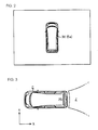
- a vehicle image 30 serving as a current position index, such as that shown in FIG. 2, is displayed.
- the display 8 is a touch panel, and when an input operation is performed on the touch panel, a signal corresponding to the input operation is output to the control unit 3 via a user input interface unit (to be referred to hereafter as a user input I/F unit 10) provided in the control device 2. Likewise, when an input operation is performed by the user on an operating switch 9 provided adjacent to the display 8, a signal corresponding to the input operation is output to the control unit 3 via the user input I/F unit 10.
- the control device 2 also has a voice processor 11.
- the voice processor 11 includes memory storing a voice file, a digital/analog converter, and so on, not shown in the drawing, and uses the voice file to output a guiding voice or warning voice through a speaker 12 installed in the parking assist system 1.
- the control device 2 also has a vehicle side interface unit (to be referred to hereafter as a vehicle side I/F unit 13). Through the vehicle side I/F unit 13, the control unit 3 inputs a vehicle speed pulse VP from a vehicle speed sensor 20 provided in a vehicle C, and counts the pulse count. The control unit 3 also inputs a bearing detection signal GRP from a gyroscope 21 via the vehicle side I/F unit 13, and updates the current bearing, which is a variable stored in the main memory 4.
- a vehicle side interface unit to be referred to hereafter as a vehicle side I/F unit 13
- the control unit 3 inputs a vehicle speed pulse VP from a vehicle speed sensor 20 provided in a vehicle C, and counts the pulse count.
- the control unit 3 also inputs a bearing detection signal GRP from a gyroscope 21 via the vehicle side I/F unit 13, and updates the current bearing, which is a variable stored in the main memory 4.
- the control unit 3 also inputs a shift position signal SPP from a neutral start switch 22 of the vehicle C via the vehicle side I/F unit 13, and updates the shift position, which is a variable stored in the main memory 4.
- the control unit 3 also inputs a steering sensor signal STP from a steering angle sensor 23 via the vehicle side I/F unit 13. On the basis of the steering sensor signal STP, the control unit 3 updates the current steering angle of the vehicle C, which is stored in the main memory 4.
- the control unit 3 When the shift position signal SPP indicating reverse is input, the control unit 3 sets the position of the vehicle at this time as a reference position. Then, on the basis of the vehicle speed pulse VP and the steering sensor signal STP, the control unit 3 calculates relative coordinates and a relative steering angle from the reference position.
- the control device 2 also has an image data input unit 14 serving as an image data obtaining mechanism.
- the image data input unit 14 obtains image data G successively by drive-controlling a back monitor camera (to be referred to hereafter simply as a camera 25), which serves as an imaging device provided in the vehicle C, in accordance with the control of the control unit 3.
- a back monitor camera to be referred to hereafter simply as a camera 25
- the camera 25 is attached to the rear end of the vehicle, for example the trunk door of the vehicle C, such that the optical axis is oriented downward.
- the camera 25 is a digital camera for capturing color images, and has an optical mechanism constituted by a wide angle lens, a mirror, and so on, and a CCD imaging element (neither of which are shown in the drawing).
- the camera 25 has a visual field of 140 degrees to the left and right, for example, and an imaging region Z which extends rearward for several meters, including the rear end of the vehicle C.
- the image data input unit 14 obtains image data G that have been subjected to analog/digital conversion by the camera 25, and stores the image data G temporarily in image memory 17 serving as an image data storage mechanism provided in the control device 2.
- the camera 25 may output an image signal to the image data input unit 14, whereupon the image data input unit 14 performs analog/digital conversion on the basis of the image signal to generate the image data G.
- the control device 2 also has an image processor 15 serving as an image processing mechanism, an output control mechanism, a first index rendering mechanism, a second index rendering mechanism, a defining line detecting mechanism, a vehicle position rendering mechanism, and an image synthesizing mechanism.
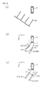
- the image processor 15 inputs image data G such as those shown in pattern form in FIG. 4A via the image data input unit 14. Then, by subjecting the image data G to known geometric conversion, bird's-eye view data G1 serving as recorded image data, such as those shown in FIG. 4B, are generated.
- the viewpoint of the camera 25 is located diagonally upward from the road surface, but the bird's-eye view data G1 are converted into image data in which the road surface is seen from above in a vertical direction.
- the image processor 15 inputs from the control unit 3 coordinate data indicating the relative coordinates from the reference position and steering angle data indicating a relative steering angle having the steering angle in the reference position as a reference. Then, as shown in FIG. 5, the bird's-eye view data G1 are written into an area indicated by a solid line, which corresponds to the coordinate data and steering angle data, of a memory area A of the image memory 17.
- the bird's-eye view data G1 of a reversed position from the reference position after writing the bird's-eye view data G1 of the reference position the bird's-eye view data G1 are overwritten into an area indicated by a dot-dash line on the basis of the relative coordinates and relative steering angle based on the reference position.
- Pixel values of the newer bird's-eye view data G1 are selected and written into the area in which the bird's-eye view data G1 overlap. In so doing, an image based on the previously written bird's-eye view data G1 and an image based on the latterly written bird's-eye view data G1 form a continuous image. Thus, every time the vehicle C reverses by the image recording distance D1, bird's-eye view data G1 captured at each imaging point are accumulated in the image memory 17.
- the image processor 15 reads the bird's-eye view data G1 in a predetermined area. Furthermore, latest image data G reflecting the current conditions on the periphery of the vehicle (to be referred to hereafter as current image data G2) are newly obtained from the camera 25. After subjecting the current image data G2 to bird's-eye view conversion, the bird's-eye view data G1 and the bird's-eye view-converted current image data G2 are subjected to synthesis processing, whereupon synthesis-processed synthesized data G3 are displayed on the display 8.
- the image processor 15 renders guide lines on the synthesized image of the bird's-eye view data G1 and the current image data G2. More specifically, first the image processor 15 performs detection processing to detect white lines defining the target parking area. In this embodiment, this processing employs well-known edge extraction processing. For example, the synthesized data G3 forming a color image are converted into grayscale data, and thresholds such as an average brightness value and a median value are set. Then, when the brightness gradient or the like between pixels is less than the threshold, an edge is not detected, and when the brightness gradient or the like is equal to or greater than the threshold, an edge is detected.
- the brightness of each pixel of the bird's-eye view data G1 converted into grayscale data and the pixel value difference between each pixel and the adjacent pixel thereto is detected. Then, a pixel having a large difference is detected as an edge.
- FIG. 6A for example, when white lines 100 serving as defining lines to the rear of the vehicle are captured by the camera 25 and bird's-eye view data G1 are generated, the synthesized data G3 using these bird's-eye view data G1 are subjected to edge detection, and as a result, the white lines 100 are extracted as edges EG, as shown in FIG. 6B.
- a discontinuous edge EG may be detected as a result of edge extraction, and therefore the image processor 15 performs Hough transform, for example, on the basis of the edge extraction result to recognize the edge EG as a straight line (segment) within the image space.
- the image processor 15 then sets the straight line (segment) determined in this manner as a white line approximation Sg.
- the image processor 15 determines a pair of predicted course lines Tr of the vehicle C corresponding to the vehicle width as an expression within the image coordinate system (Xi, Yj), and determines a contact point between the predicted course line Tr and the white line approximation Sg. As shown in FIG. 6B, when the predicted course line Tr and the white line approximation Sg do not contact, a parallel expression Sg1 which is parallel to the white line approximation Sg and contacts the predicted course line Tr is calculated.
- the first segment St1 indicates a rear axle position when the vehicle C reverses along the predicted course lines Tr from its current position so as to become parallel to the white line approximations Sg.
- the rear axle of the vehicle C will match the first segment St1. Accordingly, if the vehicle C drives straight back once the rear axle of the vehicle C has matched the first segment St1, the vehicle C can be parked parallel to the white lines 100.
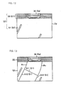
- the image processor 15 determines second segments St2 serving as straight driving course lines having a substantially identical length to the vehicle length, which are parallel to the white line approximations Sg or the parallel expressions Sg1 from the contact points P1, P2. From the second segments St2, the relative distance between the vehicle body and the white lines 100 can be learned, and therefore, the leeway on either side of the vehicle C after turning at the current steering angle and then driving in a straight line can be learned.
- the first segment St1 and second segments St2 constitute straight driving guide lines St serving as straight driving guide index for providing information relating to straight driving following turning.
- the image processor 15 cuts the predicted course lines Tr to determine turning guide lines Rv serving as a predicted route index corresponding to the length from the rear end of the vehicle to the first segment St1.
- the turning guide lines Rv and straight driving guide lines St are superposed onto the image based on the synthesized data G3.
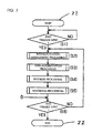
- the control unit 3 waits for input of a start trigger in accordance with the parking assist program stored in the ROM 5 (step S1).
- the start trigger is an input signal generated upon activation of an ignition module (not shown).
- system activation management processing step S2
- data accumulation processing step S3
- synthesis processing step S4
- rendering processing step S5
- step S6 determines whether or not an end trigger has been input
- the end trigger is an input signal generated when the ignition module is switched OFF or the parking assist system 1 is shut down.
- the control unit 3 inputs the shift position signal SPP via the vehicle side I/F unit 13, and updates the shift position, which is a variable stored in the main memory 4 (step S2-1). Then, the control unit 3 determines whether or not the shift position is reverse (step S2-2). When the shift position is determined to be reverse (YES in the step S2-2), the current position of the vehicle C is set as the reference position.
- control unit 3 determines whether or not a system activation flag stored in the main memory 4 is OFF (step S2-3).
- the system activation flag is a flag indicating whether or not a parking assist mode has been activated. Having determined that the system activation flag is ON (NO in the step S2-3), the control unit 3 advances to the subsequent data accumulation processing (step S3).
- the control unit 3 determines that the system activation flag is OFF (YES in the step S2-3). In this case, the control unit 3 updates the system activation flag to ON (step S2-4). Further, the control unit 3 initializes a reversing distance ⁇ DM, which is a variable stored in the main memory 4, to "0" (step S2-5). Further, through the control of the control unit 3, the image processor 15 inputs the image data G from the camera 25 via the image data input unit 14 (step S2-6), and subjects the image data G to bird's-eye view conversion (step S2-7), as shown in FIG. 4A and 4B, to generate the bird's-eye view data G1.
- ⁇ DM a reversing distance
- the image processor 15 stores the bird's-eye view data G1 in a data area corresponding to the reference position within the image memory 17 via the control unit 3 (step S2-8). After storing the reference position bird's-eye view data G1, the routine advances to the subsequent data accumulation processing.
- the control unit 3 inputs a vehicle signal constituted by the vehicle speed pulse VP and the steering sensor signal STP (step S3-1). As described above, the control unit 3 counts the pulse count on the basis of the vehicle speed pulse VP input as the vehicle C reverses. Then, on the basis of the pulse count, the control unit 3 updates a movement amount ⁇ d stored in the main memory 4 (step S3-2). Further, the control unit 3 updates the reversing distance ⁇ DM by adding the movement amount ⁇ d to the reversing distance ⁇ DM initialized in the step S2-5 (step S3-3). When the reversing distance ⁇ DM is updated, the movement amount ⁇ d is reset. A determination is then made as to whether or not the reversing distance ⁇ DM is equal to or greater than the image recording distance D1 (step S3-4). In this embodiment, the image recording distance D1 is set at 100 mm.
- step S6 determines whether or not the end trigger has been input.
- the routine returns to the system activation management processing (step S2).
- the image processor 15 inputs image data G for recording (step S3-5). These image data G are then subjected to bird's-eye view conversion to generate bird's-eye view data G1 such as those shown in FIG. 4B (step S3-6).
- the image processor 15 also inputs coordinate data and steering angle data relating to the time at which the image data G for recording were captured, and writes the bird's-eye view data G1 in a position corresponding to the coordinate data and steering angle data within the memory area of the image memory 17 (step S3-7).
- a data counter stored in the main memory 4 is incremented, and the reversing distance ⁇ DM is initialized to "0" (step S3-8).
- the control unit 3 determines whether or not a predetermined amount of bird's-eye view data G1 has been stored in the image memory 17 (step S3-9).
- the predetermined amount is set at 10, for example, and when the control unit 3 determines that the predetermined amount of bird's-eye view data G1 has been stored (YES in the step S3-9), a display possible flag stored in the main memory 4 is switched ON (step S3-10), and the routine advances to the subsequent synthesis processing (step S4).
- the display possible flag is a flag indicating whether or not synthesized data G3 employing the bird's-eye view data G1 can be synthesized.
- the routine advances to the step S6, where a determination is made as to whether or not the end trigger has been input, and when the end trigger has not been input, the routine returns to the step S2.
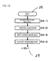
- the image processor 15 extracts a predetermined area based on the current coordinates and current steering angle of the vehicle C from a memory area A of the main memory 17 in which the bird's-eye view data G1 are written (step S4-1).
- pixel values of the bird's-eye view data G1 written in an area corresponding to the current rear portion of the vehicle C and the periphery thereof are read from the memory area A of the image memory 17.
- the extracted bird's-eye view data G1 are rotated in accordance with the current steering angle (step S4-2).
- the image processor 15 inputs the current image data G2 from the camera 25 (step S4-3), and generates the synthesized data G3 using the bird's-eye view data G1 and current image data G2 (step S4-4). More specifically, as shown in FIG. 12, the image processor 15 disposes the rotated bird's-eye view data G1 at the top of a display area Zd of the display 8. The image processor 15 also subjects the current image data G2 to bird's-eye view conversion and disposes the bird's-eye view-converted current image data G2 at the bottom of the display area Zd of the display 8. Thus, a recorded image 50 serving as a peripheral image based on the bird's-eye view data G1 is displayed at the top of the display area Zd.
- the recorded image 50 is an image displaying the current rear portion of the vehicle C and the periphery thereof, and displays the current dead angle area of the camera 25.
- a current image 51 serving as a peripheral image based on the current image data G2 is displayed at the bottom of the display area Zd.
- the current image 51 is an image of the current imaging area Z of the camera 25, and serves as a bird's-eye view image of the road surface included in the imaging area Z.
- the image processor 15 performs the rendering processing shown in FIG. 11.
- the image processor 15 performs the white line detection processing described above on the synthesized data G3 (step S5-1).
- the image processor 15 converts the synthesized data G3 into grayscale data and performs edge extraction on the basis of the brightness of each pixel.
- the image processor 15 performs Hough transform or the like on the edge extraction result to calculate white line approximations Sg such as those shown in FIG. 6B (step S5-2).
- white line approximations Sg such as those shown in FIG. 6B
- control unit 3 inputs the steering sensor signal STP via the vehicle side I/F unit 13 (step S5-3), and calculates the predicted course lines Tr (step S5-4).
- the contact points P1, P2 between the predicted course lines Tr and the white line approximations Sg are calculated (step S5-5). As described above, when the predicted course lines Tr and white line approximations Sg do not contact each other, parallel expressions Sg1 that are parallel to the white line approximations Sg and contact the predicted course lines Tr are calculated, and the contact points P1, P2 between the predicted course lines Tr and parallel expressions Sg1 are determined.
- step S5-6 the image processor 15 cuts the predicted course lines Tr from the vehicle rear end to the contact points P1, P2, and sets the resulting segments as the turning guide lines Rv, as shown in FIG. 6C.
- the image processor 15 calculates the straight driving guide lines St (step S5-7). In other words, as described above, the contact points P1, P2 are connected and the resulting first segment St1 is determined as a straight line expression. Further, using the contact points P1, P2 as starting points, the image processor 15 calculates the pair of second segments St2 parallel to the respective white line approximations Sg or parallel expressions Sg1.
- the image processor 15 outputs the synthesized data G3 stored in the VRAM 16 to the display 8 (step S5-8).
- the image processor 15 also outputs the vehicle image data 5a to a predetermined position, and displays a synthesized image 52 serving as a peripheral image such as that shown in FIG. 12 on the display 8 (step S5-9).
- the image processor 15 then outputs the turning guide lines Rv and the straight driving guide lines St to the synthesized image 52 (step S5-10).
- a parking assist screen 55 such as that shown in FIG. 13 is displayed on the display 8.
- the driver confirms the deviation between the straight driving guide lines St and the white lines on the synthesized image 52, and when the vehicle C may be turned at the current steering angle, the driver turns the vehicle C while maintaining the current steering wheel operation until the rear axle of the vehicle C reaches the first segment St1.
- the driver determines that the current steering angle must be modified when the deviation between the straight driving guide lines St and the white lines on the synthesized image 52 is large or that the gap between each white line and each second segment St2 is too large, the driver turns the steering wheel. At this time, all of the processes described above are repeated, and the turning guide lines Rv and straight driving guide lines St are rendered anew.
- the driver turns the vehicle C while maintaining the steering angle such that when the rear axle of the vehicle C reaches the first segment St1, the vehicle C is substantially parallel to the white lines.
- a parking assist screen 55 such as that shown in FIG. 14 is displayed on the display 8.
- the turning guide lines Rv are no longer displayed, and the straight driving guide lines St are superposed on the current image 51.
- the driver turns the steering wheel back and drives the vehicle C straight back so that the vehicle C can be parked in an appropriate position within the target parking area.
- the control unit 3 determines that the shift position is not reverse in the step S2-2 of FIG. 8 (NO in the step S2-2), and then determines whether or not the system activation flag is ON (step S2-9).
- the system activation flag is OFF (NO in the step S2-9), and therefore the control unit 3 determines whether or not the end trigger has been input (step S6).
- the system activation flag remains ON.
- control unit 3 determines that the system activation flag is ON (YES in the step S2-9), and resets the variables stored in the main memory 4 (step S2-10). The control unit 3 then switches the system activation flag OFF (step S2-11). When the end trigger is input (YES in the step S6), the processing is terminated.
- FIGS. 15 and 16 a second embodiment of the present invention will be described using FIGS. 15 and 16. Note that in the second embodiment, only the straight driving guide lines St of the first embodiment are modified, and therefore detailed description of identical parts has been omitted.
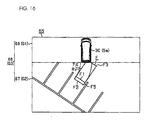
- the image processor 15 renders a straight driving guide frame F as the predicted position index instead of the straight driving guide lines St.
- the straight driving guide frame F shows the outer form of the vehicle in a position where the vehicle C is parallel to the white line approximations Sg.
- the straight driving guide frame F is constituted by a predicted axle position F1, a predicted rear end position F2, a predicted front end position F3, and predicted side end positions F4, F5.
- the predicted axle position F1 denotes the predicted position of the rear axle when the vehicle C reverses from its current position along the predicted course lines Tr (see FIG. 6), i.e. without turning the steering wheel, such that the vehicle C becomes parallel to the white line approximations Sg.
- the predicted axle position F1 is rendered by a solid line, but may be rendered using broken lines. Note that the predicted axle position F1 is rendered in the same position as the first segment St1 of the first embodiment.
- the predicted rear end position F2 and the predicted front end position F3 are lines rendered to predict the positions of the rear end and front end of the vehicle C, respectively, when the vehicle C reverses along the predicted course lines Tr (see FIG. 6) such that the vehicle C becomes parallel to the white line approximations Sg.
- the predicted side end positions F4, F5 show the side ends of the vehicle C when the rear wheel, rear end, or front end of the vehicle C is in the predicted axle position F1, predicted rear end position F2, or predicted front end position F3.
- the predicted axle position F1 is rendered in a direction intersecting the white line approximations Sg
- the predicted side end positions F4, F5 are rendered parallel to the white line approximations Sg.
- the image processor 15 When the coordinates of the straight driving guide frame F are calculated on the basis of the contact points P1, P2 (step S5-7), the image processor 15 outputs synthesized data G3 such as that of the first embodiment to the display 8 (step S5-8). Further, the image processor 15 outputs the vehicle image data 5a to a predetermined position in the display area Zd of the display 8 (step S5-9).
- the image processor 15 Having outputted the synthesized data G3 and vehicle image data 5a, the image processor 15 outputs the straight driving guide frame F, the coordinates of which were calculated in the step S5-7, and the turning guide lines Rv as guide lines (step S5-9).
- a parking assist screen 65 such as that shown in FIG. 16 is displayed on the display 8.
- a synthesized image 66 based on the synthesized data G3 is displayed on the parking assist screen 66.
- the extraction range of the bird's-eye view data G1 is large, and therefore a wider vehicle periphery area than that of the first embodiment is rendered.
- the synthesized image 66 displays a current image 67 based on the current image data G2, and a recorded image 68 based on the bird's-eye view data G1 captured and accumulated in the image memory 17 in the past. Further, a vehicle image 30 showing the entire vehicle is superposed on the recorded image 68.
- the straight driving guide frame F and the turning guide lines Rv are superposed on the synthesized image 66.
- the straight driving guide frame F is rendered at substantially the same size as the size of the vehicle C, and therefore the user can understand intuitively that the straight driving guide frame F denotes the position of the vehicle after turning in accordance with the turning guide lines Rv. Further, the fact that the straight driving guide frame F is parallel to the white lines rendered on the synthesized image 66 can be confirmed from the screen, and therefore the driver can understand intuitively that the vehicle C should be driven straight back from the straight driving guide frame F.
- the routine advances to the step S6, where a determination is made as to whether or not the end trigger has been input.
- the bird's-eye view data G1 are written into a corresponding area of the memory area A of the main memory 17, but the bird's-eye view data G1 may be stored in association with the coordinate data and steering angle data. Further, the image data G may be stored in the image memory 17 without being subjected to bird's-eye view conversion.
- the image recording distance D1 is set at 100 mm, but may be set at another distance.
- the bearing detection signal GRP based on the gyroscope 21 may be used instead of the steering sensor signal STP during data accumulation and image processing.
- the synthesized image 52 may be generated using a synthesis method other than the procedure described above.
- the bird's-eye view data subjected to bird's-eye view conversion may be output to the display 8 immediately, without accumulating the image data input from the camera 25.
- the turning guide lines Rv and straight driving guide lines St may be rendered on a peripheral image of the front, rear, or another peripheral viewpoint of the vehicle C. Note that when the image data G are displayed on the display 8 without being subjected to bird's-eye view conversion and edge extraction is performed to calculate the turning guide lines Rv and straight driving guide lines St, edge extraction may be performed as is, without subjecting the image data G to bird's-eye view conversion.
- the display possible flag is switched ON when the predetermined amount of bird's-eye view data G1 has accumulated in the image memory 17, but the display possible flag may be switched ON when bird's-eye view data G1 have been written into an entire predetermined data area.
- the display possible flag may be switched ON or the synthesized image 52 (recorded image 50) may be displayed when only one set of bird's-eye view data G1 has accumulated in the image memory 17.
- a non-display image such as a mask may be displayed in the areas in which bird's-eye view data G1 have not accumulated.
- the parking assist screen 55, 65 may be a screen displaying the guide lines Rv, St and the current image 51 and omitting the recorded image 50, 68.
- the turning guide lines Rv and straight driving guide lines St may be guide lines other than those described above.
- a third segment St3 parallel to the first segment St1 may be rendered at the terminals of the second segments St2 to illustrate the size of the vehicle body.
- the second segments St2 may be omitted such that only the first segment St1 of the straight driving guide lines St is rendered.
- an index 60 indicating the straight driving start position may be displayed in the vicinity of the first segment St1.
- the first segment St1 may be omitted such that only the second segments St2 are rendered.
- a voice 61 saying "Drive straight" or the like may be output through the speaker 12 when the vehicle C approaches the first segment St1 or the like.
- the guide lines Rv, St are only rendered when the pair of white line approximations Sg are calculated, but the guide lines Rv, St may be rendered when only one white line approximation Sg can be calculated.
- the image processor 15 determines a contact point P1 between a single white line approximation Sg (or a parallel expression parallel to the white line approximation Sg) and a predicted course line Tr.
- a perpendicular V of the white line approximation Sg (or parallel expression) passing through the contact point P1 is then determined, and a contact point P3 between the perpendicular V and the other predicted course line Tr is determined.
- a fourth segment St4 connecting the contact point P1 and the contact point P3 is then determined.
- the fourth segment St4 denotes the straight driving start position in the first embodiment, similarly to the first segment St1, and denotes the predicted axle position F1 in the second embodiment.
- second segments St2 parallel to the white line approximation Sg or a straight driving guide frame F are rendered using the contact point P1 and the contact point P3 as starting points.
- the image processor 15 may detect the edges of other parked vehicles instead of the white lines.
- the contact points P1, P2 between the edges and the predicted course lines Tr may then be determined recognizing the space between the edges as the target parking area, and the turning guide lines Rv and straight driving guide lines St may be determined therefrom.
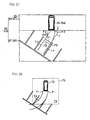
- the vehicle image 30 showing only the rear portion of the vehicle C may be displayed, as shown in a parking assist screen 69 of FIG. 19.
- the entire straight driving guide frame F need not be included in a synthesized image 69a as long as at least a part of the straight driving guide frame F is included.
- the straight driving guide frame F may be formed in a square frame shape omitting the predicted axle position F1. Further, as shown in FIG. 20B, the straight driving guide frame F may be constituted by corner positions F6 to F10 indicating each corner portion of the vehicle C when the vehicle C is parallel to the white line approximations Sg, and the predicted axle position F1.
- predicted straight driving course lines Ls may be rendered on the reverse direction (driving direction) side of the straight driving guide frame F.
- the predicted straight driving course lines Ls are rendered on the lines of extension of the predicted side end positions F4, F5, and denote the predicted course when reversing from the straight driving guide frame F.
- the predicted straight driving course lines Ls correspond to the second segments St2 of the first embodiment. In so doing, the relative distance and relative direction between the vehicle C and the white lines after reversing from the straight driving guide frame F can be grasped.
- the first segment St1 and the predicted axle position F1 are rendered as the rear axle position when the vehicle C becomes parallel to the target parking area.
- the first segment St1 and predicted axle position F1 may be rendered as the predicted position of the rear end of the vehicle C.
- the vehicle C can be parked in the target parking area by turning along the turning guide lines Rv until the rear end of the vehicle C matches the first segment St1 or the predicted axle position F1, and then turning the steering wheel so as to drive straight back.
- the parking assist screen 55 is displayed on the basis of the image data G generated by the camera 25 attached to the rear end of the vehicle, but a camera attached to the side end or front end of the vehicle may be used.
- a camera attached to the front end of the vehicle is used, parking assistance can be performed when the vehicle C parks by driving forward.
Landscapes
- Engineering & Computer Science (AREA)
- Chemical & Material Sciences (AREA)
- Combustion & Propulsion (AREA)
- Transportation (AREA)
- Mechanical Engineering (AREA)
- Physics & Mathematics (AREA)
- General Physics & Mathematics (AREA)
- Closed-Circuit Television Systems (AREA)
- Image Processing (AREA)
- Image Analysis (AREA)
- Traffic Control Systems (AREA)
Applications Claiming Priority (2)
| Application Number | Priority Date | Filing Date | Title |
|---|---|---|---|
| JP2006148698 | 2006-05-29 | ||
| JP2006313510A JP5309442B2 (ja) | 2006-05-29 | 2006-11-20 | 駐車支援方法及び駐車支援装置 |
Publications (4)
| Publication Number | Publication Date |
|---|---|
| EP1862375A2 true EP1862375A2 (de) | 2007-12-05 |
| EP1862375A3 EP1862375A3 (de) | 2008-12-31 |
| EP1862375B1 EP1862375B1 (de) | 2011-09-07 |
| EP1862375B9 EP1862375B9 (de) | 2012-01-25 |
Family
ID=38457589
Family Applications (1)
| Application Number | Title | Priority Date | Filing Date |
|---|---|---|---|
| EP07009506A Not-in-force EP1862375B9 (de) | 2006-05-29 | 2007-05-11 | Einparkhilfsverfahren und Einparkhilfsvorrichtung |
Country Status (3)
| Country | Link |
|---|---|
| US (1) | US7969326B2 (de) |
| EP (1) | EP1862375B9 (de) |
| JP (1) | JP5309442B2 (de) |
Cited By (5)
| Publication number | Priority date | Publication date | Assignee | Title |
|---|---|---|---|---|
| EP2301812A4 (de) * | 2008-06-10 | 2012-08-22 | Nissan Motor | Parkhilfevorrichtung und parkhilfeverfahren |
| EP2776295A4 (de) * | 2011-11-08 | 2015-10-07 | Lg Innotek Co Ltd | Parkhilfesystem |
| KR20150123094A (ko) * | 2014-04-24 | 2015-11-03 | 현대모비스 주식회사 | 어라운드 뷰 시스템의 동작방법 |
| EP2927077A4 (de) * | 2012-11-27 | 2016-04-27 | Nissan Motor | Vorrichtung zur unterdrückung einer fahrzeugbeschleunigung |
| TWI749143B (zh) * | 2017-01-13 | 2021-12-11 | 日商阿爾派股份有限公司 | 停車支援裝置及行駛預測線顯示方法 |
Families Citing this family (117)
| Publication number | Priority date | Publication date | Assignee | Title |
|---|---|---|---|---|
| US11767016B2 (en) * | 2002-06-04 | 2023-09-26 | Transportation Ip Holdings, Llc | Optical route examination system and method |
| JP4561456B2 (ja) * | 2005-04-21 | 2010-10-13 | アイシン・エィ・ダブリュ株式会社 | 駐車支援方法及び駐車支援装置 |
| GB2447672B (en) | 2007-03-21 | 2011-12-14 | Ford Global Tech Llc | Vehicle manoeuvring aids |
| TWI334517B (en) * | 2007-08-30 | 2010-12-11 | Ind Tech Res Inst | Method for predicting lane line and lane departure warning system using the same |
| JP2009071659A (ja) * | 2007-09-14 | 2009-04-02 | Alpine Electronics Inc | 駐車支援装置 |
| JP5088074B2 (ja) * | 2007-10-01 | 2012-12-05 | 日産自動車株式会社 | 駐車支援装置及び方法 |
| JP5380941B2 (ja) * | 2007-10-01 | 2014-01-08 | 日産自動車株式会社 | 駐車支援装置及び方法 |
| US8503728B2 (en) * | 2007-10-30 | 2013-08-06 | Nec Corporation | Road marking image processing device, road marking image processing method, and program |
| JP4900232B2 (ja) * | 2007-12-26 | 2012-03-21 | 日産自動車株式会社 | 車両用駐車支援装置および映像表示方法 |
| DE102008003662A1 (de) * | 2008-01-09 | 2009-07-16 | Robert Bosch Gmbh | Verfahren und Vorrichtung zum Anzeigen der Umgebung eines Fahrzeugs |
| KR20090088210A (ko) | 2008-02-14 | 2009-08-19 | 주식회사 만도 | 두 개의 기준점을 이용한 목표주차위치 검출 방법과 장치및 그를 이용한 주차 보조 시스템 |
| JP5400316B2 (ja) * | 2008-04-07 | 2014-01-29 | 日産自動車株式会社 | 駐車支援装置 |
| JP4661917B2 (ja) * | 2008-07-25 | 2011-03-30 | 日産自動車株式会社 | 駐車支援装置および駐車支援方法 |
| JP5309891B2 (ja) * | 2008-10-27 | 2013-10-09 | 三菱自動車工業株式会社 | 駐車支援装置 |
| JP5068779B2 (ja) * | 2009-02-27 | 2012-11-07 | 現代自動車株式会社 | 車両周囲俯瞰画像表示装置及び方法 |
| JP5035284B2 (ja) * | 2009-03-25 | 2012-09-26 | 株式会社日本自動車部品総合研究所 | 車両周辺表示装置 |
| JP2011054110A (ja) * | 2009-09-04 | 2011-03-17 | Mitsutoyo Corp | 画像処理型測定機および画像処理測定方法 |
| JP5035321B2 (ja) * | 2009-11-02 | 2012-09-26 | 株式会社デンソー | 車両周辺表示制御装置および車両周辺表示制御装置用のプログラム |
| US8396653B2 (en) * | 2010-02-12 | 2013-03-12 | Robert Bosch Gmbh | Dynamic range display for automotive rear-view and parking systems |
| JP5696872B2 (ja) | 2010-03-26 | 2015-04-08 | アイシン精機株式会社 | 車両周辺監視装置 |
| JP5472454B2 (ja) * | 2010-04-27 | 2014-04-16 | トヨタ自動車株式会社 | 駐車支援装置 |
| JP5397329B2 (ja) * | 2010-06-29 | 2014-01-22 | トヨタ自動車株式会社 | 駐車支援装置 |
| JP2012011817A (ja) * | 2010-06-29 | 2012-01-19 | Toyota Motor Corp | 駐車支援装置 |
| JP5472026B2 (ja) | 2010-06-29 | 2014-04-16 | トヨタ自動車株式会社 | 駐車支援装置 |
| US9555832B2 (en) | 2011-04-19 | 2017-01-31 | Ford Global Technologies, Llc | Display system utilizing vehicle and trailer dynamics |
| US9346396B2 (en) | 2011-04-19 | 2016-05-24 | Ford Global Technologies, Llc | Supplemental vehicle lighting system for vision based target detection |
| US9238483B2 (en) | 2011-04-19 | 2016-01-19 | Ford Global Technologies, Llc | Trailer backup assist system with trajectory planner for multiple waypoints |
| US9926008B2 (en) | 2011-04-19 | 2018-03-27 | Ford Global Technologies, Llc | Trailer backup assist system with waypoint selection |
| US9374562B2 (en) | 2011-04-19 | 2016-06-21 | Ford Global Technologies, Llc | System and method for calculating a horizontal camera to target distance |
| US9290202B2 (en) | 2011-04-19 | 2016-03-22 | Ford Global Technologies, Llc | System and method of calibrating a trailer backup assist system |
| US9937953B2 (en) | 2011-04-19 | 2018-04-10 | Ford Global Technologies, Llc | Trailer backup offset determination |
| US9708000B2 (en) | 2011-04-19 | 2017-07-18 | Ford Global Technologies, Llc | Trajectory planner for a trailer backup assist system |
| US9248858B2 (en) | 2011-04-19 | 2016-02-02 | Ford Global Technologies | Trailer backup assist system |
| US9683848B2 (en) | 2011-04-19 | 2017-06-20 | Ford Global Technologies, Llc | System for determining hitch angle |
| US9783230B2 (en) | 2011-04-19 | 2017-10-10 | Ford Global Technologies, Llc | Trailer backup assist system with off-shoot correction |
| US9854209B2 (en) | 2011-04-19 | 2017-12-26 | Ford Global Technologies, Llc | Display system utilizing vehicle and trailer dynamics |
| US9434414B2 (en) | 2011-04-19 | 2016-09-06 | Ford Global Technologies, Llc | System and method for determining a hitch angle offset |
| US9723274B2 (en) | 2011-04-19 | 2017-08-01 | Ford Global Technologies, Llc | System and method for adjusting an image capture setting |
| US9499200B2 (en) | 2011-04-19 | 2016-11-22 | Ford Global Technologies, Llc | Trailer backup assist system with object detection |
| US9500497B2 (en) | 2011-04-19 | 2016-11-22 | Ford Global Technologies, Llc | System and method of inputting an intended backing path |
| US9493187B2 (en) | 2011-04-19 | 2016-11-15 | Ford Global Technologies, Llc | Control for trailer backup assist system |
| US9969428B2 (en) | 2011-04-19 | 2018-05-15 | Ford Global Technologies, Llc | Trailer backup assist system with waypoint selection |
| US8909426B2 (en) | 2011-04-19 | 2014-12-09 | Ford Global Technologies | Trailer path curvature control for trailer backup assist |
| US9506774B2 (en) | 2011-04-19 | 2016-11-29 | Ford Global Technologies, Llc | Method of inputting a path for a vehicle and trailer |
| US9290204B2 (en) | 2011-04-19 | 2016-03-22 | Ford Global Technologies, Llc | Hitch angle monitoring system and method |
| CN102795166A (zh) * | 2011-05-25 | 2012-11-28 | 怡利电子工业股份有限公司 | 倒车轨迹导引方法 |
| JP5798392B2 (ja) * | 2011-06-27 | 2015-10-21 | クラリオン株式会社 | 駐車支援装置 |
| CN103827941B (zh) * | 2011-09-26 | 2016-03-16 | 丰田自动车株式会社 | 车辆的驾驶辅助系统 |
| JP2012030797A (ja) * | 2011-11-14 | 2012-02-16 | Nissan Motor Co Ltd | 駐車支援装置及び駐車支援方法 |
| JP4924770B2 (ja) * | 2011-11-14 | 2012-04-25 | 日産自動車株式会社 | 駐車支援装置及び駐車支援方法 |
| KR101327736B1 (ko) * | 2011-12-23 | 2013-11-11 | 현대자동차주식회사 | Avm탑뷰 기반 주차지원 시스템 |
| US9598836B2 (en) | 2012-03-29 | 2017-03-21 | Harnischfeger Technologies, Inc. | Overhead view system for a shovel |
| JP5888087B2 (ja) | 2012-04-25 | 2016-03-16 | ソニー株式会社 | 走行支援画像生成装置、走行支援画像生成方法、車載用カメラおよび機器操縦支援画像生成装置 |
| KR101387189B1 (ko) * | 2012-05-30 | 2014-04-29 | 삼성전기주식회사 | 운행 보조정보 표시장치 및 운행 보조정보 표시방법 |
| US20140057237A1 (en) * | 2012-08-27 | 2014-02-27 | Stephen Chen | Method for parking a vehicle by using a parking assistant system |
| JP5629740B2 (ja) * | 2012-09-21 | 2014-11-26 | 株式会社小松製作所 | 作業車両用周辺監視システム及び作業車両 |
| TWI578271B (zh) * | 2012-10-23 | 2017-04-11 | 義晶科技股份有限公司 | 動態影像處理方法以及動態影像處理系統 |
| DE102012023706A1 (de) * | 2012-12-05 | 2014-06-05 | Daimler Ag | Fahrzeugseitiges Verfahren und fahrzeugseitige Vorrichtung zum Erfassen und Anzeigen von Parklücken für ein Fahrzeug |
| US20140160287A1 (en) * | 2012-12-07 | 2014-06-12 | E-Lead Electronic Co., Ltd. | Guide method of a reverse guideline system |
| TWI494899B (zh) | 2012-12-19 | 2015-08-01 | Ind Tech Res Inst | 影像內週期性雜訊修補方法 |
| US9068390B2 (en) * | 2013-01-21 | 2015-06-30 | Magna Electronics Inc. | Vehicle hatch control system |
| US9592851B2 (en) | 2013-02-04 | 2017-03-14 | Ford Global Technologies, Llc | Control modes for a trailer backup assist system |
| US9511799B2 (en) | 2013-02-04 | 2016-12-06 | Ford Global Technologies, Llc | Object avoidance for a trailer backup assist system |
| JP5966961B2 (ja) * | 2013-02-14 | 2016-08-10 | 株式会社デンソー | 駐車支援装置 |
| US9352777B2 (en) | 2013-10-31 | 2016-05-31 | Ford Global Technologies, Llc | Methods and systems for configuring of a trailer maneuvering system |
| KR101470240B1 (ko) * | 2013-11-14 | 2014-12-08 | 현대자동차주식회사 | 주차 영역 검출 장치 및 그 방법 |
| DE102013225773A1 (de) * | 2013-12-12 | 2015-06-18 | Robert Bosch Gmbh | Rückraumüberwachungsystem und Verfahren zur Rückraumüberwachung eines Fahrzeugs |
| DE102013114563A1 (de) * | 2013-12-19 | 2015-06-25 | Valeo Schalter Und Sensoren Gmbh | Verfahren zum Durchführen eines Einparkvorgangs eines Kraftfahrzeugs in eine Querparklücke, Parkassistenzsystem und Kraftfahrzeug |
| KR101498976B1 (ko) * | 2013-12-19 | 2015-03-05 | 현대모비스(주) | 차량용 주차지원시스템 및 주차지원방법 |
| JP6206258B2 (ja) * | 2014-03-06 | 2017-10-04 | 富士通株式会社 | 軌跡推定装置、軌跡推定方法およびプログラム |
| US9233710B2 (en) | 2014-03-06 | 2016-01-12 | Ford Global Technologies, Llc | Trailer backup assist system using gesture commands and method |
| US9623904B2 (en) | 2014-06-03 | 2017-04-18 | Ford Global Technologies, Llc | Trailer curvature control with adaptive trailer length estimation |
| KR102268641B1 (ko) * | 2014-07-10 | 2021-06-23 | 현대모비스 주식회사 | 어라운드 뷰 시스템 및 그 동작방법 |
| US9540043B2 (en) | 2014-07-30 | 2017-01-10 | Ford Global Technologies, Llc | Trailer backup assist system with active trailer braking for curvature control |
| US9725040B2 (en) | 2014-10-28 | 2017-08-08 | Nissan North America, Inc. | Vehicle object detection system |
| US9880253B2 (en) | 2014-10-28 | 2018-01-30 | Nissan North America, Inc. | Vehicle object monitoring system |
| US9834141B2 (en) | 2014-10-28 | 2017-12-05 | Nissan North America, Inc. | Vehicle object detection system |
| US9533683B2 (en) | 2014-12-05 | 2017-01-03 | Ford Global Technologies, Llc | Sensor failure mitigation system and mode management |
| US9522677B2 (en) | 2014-12-05 | 2016-12-20 | Ford Global Technologies, Llc | Mitigation of input device failure and mode management |
| US9607242B2 (en) | 2015-01-16 | 2017-03-28 | Ford Global Technologies, Llc | Target monitoring system with lens cleaning device |
| US9522699B2 (en) | 2015-02-05 | 2016-12-20 | Ford Global Technologies, Llc | Trailer backup assist system with adaptive steering angle limits |
| US10286950B2 (en) | 2015-02-10 | 2019-05-14 | Ford Global Technologies, Llc | Speed optimized trajectory control for motor vehicles |
| US9616923B2 (en) | 2015-03-03 | 2017-04-11 | Ford Global Technologies, Llc | Topographical integration for trailer backup assist system |
| US9623859B2 (en) | 2015-04-03 | 2017-04-18 | Ford Global Technologies, Llc | Trailer curvature control and mode management with powertrain and brake support |
| US9744972B2 (en) | 2015-04-09 | 2017-08-29 | Ford Global Technologies, Llc | Trailer backup aid speed limiting via braking |
| US9840240B2 (en) | 2015-04-09 | 2017-12-12 | Ford Global Technologies, Llc | Trailer backup aid speed limiting via braking |
| US20160353049A1 (en) * | 2015-05-27 | 2016-12-01 | Caterpillar Inc. | Method and System for Displaying a Projected Path for a Machine |
| US9676377B2 (en) | 2015-06-17 | 2017-06-13 | Ford Global Technologies, Llc | Speed limiting comfort enhancement |
| US9896126B2 (en) | 2015-07-08 | 2018-02-20 | Ford Global Technologies, Llc | Jackknife detection for vehicle reversing a trailer |
| US9896130B2 (en) | 2015-09-11 | 2018-02-20 | Ford Global Technologies, Llc | Guidance system for a vehicle reversing a trailer along an intended backing path |
| KR101806619B1 (ko) * | 2015-09-21 | 2017-12-07 | 현대자동차주식회사 | 차량의 주차 안내 장치 및 방법 |
| US9981662B2 (en) | 2015-10-15 | 2018-05-29 | Ford Global Technologies, Llc | Speed limiting comfort enhancement |
| WO2017068699A1 (ja) * | 2015-10-22 | 2017-04-27 | 日産自動車株式会社 | 駐車スペースの枠線の検出方法および装置 |
| US9836060B2 (en) | 2015-10-28 | 2017-12-05 | Ford Global Technologies, Llc | Trailer backup assist system with target management |
| US9983591B2 (en) * | 2015-11-05 | 2018-05-29 | Ford Global Technologies, Llc | Autonomous driving at intersections based on perception data |
| US10683035B2 (en) | 2015-12-08 | 2020-06-16 | Panasonic Intellectual Property Management Co., Ltd. | Parking assistance device, parking assistance method, and non-transitory computer readable medium |
| US9610975B1 (en) | 2015-12-17 | 2017-04-04 | Ford Global Technologies, Llc | Hitch angle detection for trailer backup assist system |
| US10112646B2 (en) | 2016-05-05 | 2018-10-30 | Ford Global Technologies, Llc | Turn recovery human machine interface for trailer backup assist |
| KR101876032B1 (ko) * | 2016-06-27 | 2018-08-02 | 현대자동차주식회사 | 주차구획 표시 장치 및 그 방법 |
| US10773721B2 (en) | 2016-10-21 | 2020-09-15 | Ford Global Technologies, Llc | Control method using trailer yaw rate measurements for trailer backup assist |
| DE102017202259A1 (de) * | 2017-02-13 | 2018-08-16 | Ford Global Technologies, Llc | Verfahren und Vorrichtung zur Unterstützung eines Parkvorganges eines Kraftfahrzeuges |
| US11124113B2 (en) | 2017-04-18 | 2021-09-21 | Magna Electronics Inc. | Vehicle hatch clearance determining system |
| US10604184B2 (en) | 2017-08-31 | 2020-03-31 | Ford Global Technologies, Llc | Adaptive steering control for robustness to errors in estimated or user-supplied trailer parameters |
| US10710585B2 (en) | 2017-09-01 | 2020-07-14 | Ford Global Technologies, Llc | Trailer backup assist system with predictive hitch angle functionality |
| US10730553B2 (en) | 2017-09-27 | 2020-08-04 | Ford Global Technologies, Llc | Adaptive steering control for robustness to errors in estimated or user-supplied trailer parameters |
| JP6953088B2 (ja) * | 2017-10-24 | 2021-10-27 | アルパイン株式会社 | 電子装置および駐車支援方法 |
| US10501082B2 (en) | 2017-11-06 | 2019-12-10 | Ford Global Technologies, Llc | Electronic locking differential |
| US10451161B2 (en) * | 2017-11-06 | 2019-10-22 | Ford Global Technologies, Llc | Electronic locking differential |
| US10875498B2 (en) | 2018-09-26 | 2020-12-29 | Magna Electronics Inc. | Vehicular alert system for door lock function |
| JP7102324B2 (ja) * | 2018-11-22 | 2022-07-19 | アルパイン株式会社 | 駐車支援システムおよび駐車支援方法 |
| US10814912B2 (en) | 2018-11-28 | 2020-10-27 | Ford Global Technologies, Llc | Trailer backup assist system having advanced user mode with selectable hitch angle limits |
| US20200282909A1 (en) * | 2019-03-07 | 2020-09-10 | GM Global Technology Operations LLC | Vehicle imaging system and method for a parking solution |
| JP7226028B2 (ja) * | 2019-04-02 | 2023-02-21 | トヨタ自動車株式会社 | 車両制御装置 |
| JP7205701B2 (ja) * | 2019-10-11 | 2023-01-17 | トヨタ自動車株式会社 | 車両警報装置 |
| CN111402132B (zh) * | 2020-03-11 | 2024-02-02 | 黑芝麻智能科技(上海)有限公司 | 倒车辅助方法及系统、图像处理器及相应的辅助驾驶系统 |
| JP7347697B2 (ja) * | 2021-01-22 | 2023-09-20 | 株式会社デンソー | 車両駐車装置および車両駐車装置に用いるプログラム |
| US12539819B2 (en) | 2022-04-07 | 2026-02-03 | Magna Electronics Inc. | Vehicular vision system with tailgate control |
Citations (2)
| Publication number | Priority date | Publication date | Assignee | Title |
|---|---|---|---|---|
| JP2002373327A (ja) | 2001-06-13 | 2002-12-26 | Denso Corp | 車両周辺画像処理装置及び記録媒体 |
| JP2004114879A (ja) | 2002-09-27 | 2004-04-15 | Clarion Co Ltd | 駐車補助装置および画像表示装置 |
Family Cites Families (12)
| Publication number | Priority date | Publication date | Assignee | Title |
|---|---|---|---|---|
| US6873643B2 (en) | 1990-11-16 | 2005-03-29 | Interdigital Technology Corporation | Spread spectrum adaptive power control communications system and method |
| JP3183284B2 (ja) * | 1999-01-19 | 2001-07-09 | 株式会社豊田自動織機製作所 | 車両の後退時の操舵支援装置 |
| JP4491978B2 (ja) * | 2000-02-29 | 2010-06-30 | アイシン精機株式会社 | 車両の後退支援装置および後退支援方法 |
| DE10109680B4 (de) * | 2000-02-29 | 2009-02-26 | Aisin Seiki K.K., Kariya | Einparkhilfsgerät und Einparkhilfsverfahren für ein Fahrzeug |
| WO2001085496A1 (en) * | 2000-05-12 | 2001-11-15 | Kabushiki Kaisha Toyota Jidoshokki | Vehicle backing support apparatus |
| JP4615766B2 (ja) * | 2000-12-15 | 2011-01-19 | 本田技研工業株式会社 | 駐車支援装置 |
| JP2002373372A (ja) | 2001-06-18 | 2002-12-26 | Mirai Seiko Kk | 自動販売装置 |
| JP2004017702A (ja) * | 2002-06-13 | 2004-01-22 | Nissan Motor Co Ltd | 駐車アシスト装置 |
| JP2004025942A (ja) * | 2002-06-21 | 2004-01-29 | Equos Research Co Ltd | 駐車操作支援装置 |
| JP4466200B2 (ja) * | 2004-04-19 | 2010-05-26 | 株式会社豊田自動織機 | 駐車支援装置 |
| DE102004027640A1 (de) | 2004-06-05 | 2006-06-08 | Robert Bosch Gmbh | Verfahren und Vorrichtung zum unterstützten Einparken eines Kraftfahrzeuges |
| JP4573242B2 (ja) * | 2004-11-09 | 2010-11-04 | アルパイン株式会社 | 運転支援装置 |
-
2006
- 2006-11-20 JP JP2006313510A patent/JP5309442B2/ja not_active Expired - Fee Related
-
2007
- 2007-05-11 EP EP07009506A patent/EP1862375B9/de not_active Not-in-force
- 2007-05-29 US US11/806,075 patent/US7969326B2/en not_active Expired - Fee Related
Patent Citations (2)
| Publication number | Priority date | Publication date | Assignee | Title |
|---|---|---|---|---|
| JP2002373327A (ja) | 2001-06-13 | 2002-12-26 | Denso Corp | 車両周辺画像処理装置及び記録媒体 |
| JP2004114879A (ja) | 2002-09-27 | 2004-04-15 | Clarion Co Ltd | 駐車補助装置および画像表示装置 |
Cited By (7)
| Publication number | Priority date | Publication date | Assignee | Title |
|---|---|---|---|---|
| EP2301812A4 (de) * | 2008-06-10 | 2012-08-22 | Nissan Motor | Parkhilfevorrichtung und parkhilfeverfahren |
| US8803707B2 (en) | 2008-06-10 | 2014-08-12 | Nissan Motor Co., Ltd. | Parking assistance system and parking assistance method |
| EP2776295A4 (de) * | 2011-11-08 | 2015-10-07 | Lg Innotek Co Ltd | Parkhilfesystem |
| US9959472B2 (en) | 2011-11-08 | 2018-05-01 | Lg Innotek Co., Ltd. | Parking assisting system |
| EP2927077A4 (de) * | 2012-11-27 | 2016-04-27 | Nissan Motor | Vorrichtung zur unterdrückung einer fahrzeugbeschleunigung |
| KR20150123094A (ko) * | 2014-04-24 | 2015-11-03 | 현대모비스 주식회사 | 어라운드 뷰 시스템의 동작방법 |
| TWI749143B (zh) * | 2017-01-13 | 2021-12-11 | 日商阿爾派股份有限公司 | 停車支援裝置及行駛預測線顯示方法 |
Also Published As
| Publication number | Publication date |
|---|---|
| JP2008007090A (ja) | 2008-01-17 |
| EP1862375B9 (de) | 2012-01-25 |
| US20070273554A1 (en) | 2007-11-29 |
| EP1862375B1 (de) | 2011-09-07 |
| JP5309442B2 (ja) | 2013-10-09 |
| US7969326B2 (en) | 2011-06-28 |
| EP1862375A3 (de) | 2008-12-31 |
Similar Documents
| Publication | Publication Date | Title |
|---|---|---|
| EP1862375B9 (de) | Einparkhilfsverfahren und Einparkhilfsvorrichtung | |
| JP4899826B2 (ja) | 駐車支援方法及び駐車支援装置 | |
| CN101631695B (zh) | 驻车辅助装置 | |
| JP4914458B2 (ja) | 車両周辺表示装置 | |
| JP4815993B2 (ja) | 駐車支援方法及び駐車支援装置 | |
| JP5035284B2 (ja) | 車両周辺表示装置 | |
| JP3947375B2 (ja) | 駐車補助装置 | |
| US9156402B2 (en) | Wide view vehicle periphery image generation apparatus | |
| EP1400410A2 (de) | Fahrassistenzsystem für Fahrzeuge | |
| EP1783035B1 (de) | Verfahren und Vorrichtung zur Einparkunterstützung für ein Kraftfahrzeug | |
| US20160207526A1 (en) | Vehicle-side method and vehicle-side device for detecting and displaying parking spaces for a vehicle | |
| JP5549235B2 (ja) | 運転支援装置 | |
| JP2005112004A (ja) | 車両後退支援装置および方法 | |
| CN101082502A (zh) | 驻车辅助方法及驻车辅助装置 | |
| EP1803602A1 (de) | Fahrhilfeverfahren und Fahrhilfevorrichtung | |
| JP2008213791A (ja) | 駐車支援方法及び駐車支援装置 | |
| JP4967620B2 (ja) | 駐車支援方法及び駐車支援装置 | |
| CN107534757B (zh) | 车辆用显示装置以及车辆用显示方法 | |
| JP2010184606A (ja) | 車両周辺表示装置 | |
| JP4946045B2 (ja) | 画像表示方法及び運転支援装置 | |
| JP4639960B2 (ja) | 車両周囲画像表示装置 | |
| JP4736650B2 (ja) | 駐車支援方法及び駐車支援装置 | |
| JP6665630B2 (ja) | 運転支援方法及び運転支援装置 | |
| JP2005035542A (ja) | 駐車補助装置 | |
| JP2007076425A (ja) | 駐車支援方法及び駐車支援装置 |
Legal Events
| Date | Code | Title | Description |
|---|---|---|---|
| PUAI | Public reference made under article 153(3) epc to a published international application that has entered the european phase |
Free format text: ORIGINAL CODE: 0009012 |
|
| AK | Designated contracting states |
Kind code of ref document: A2 Designated state(s): AT BE BG CH CY CZ DE DK EE ES FI FR GB GR HU IE IS IT LI LT LU LV MC MT NL PL PT RO SE SI SK TR |
|
| AX | Request for extension of the european patent |
Extension state: AL BA HR MK YU |
|
| PUAL | Search report despatched |
Free format text: ORIGINAL CODE: 0009013 |
|
| AK | Designated contracting states |
Kind code of ref document: A3 Designated state(s): AT BE BG CH CY CZ DE DK EE ES FI FR GB GR HU IE IS IT LI LT LU LV MC MT NL PL PT RO SE SI SK TR |
|
| AX | Request for extension of the european patent |
Extension state: AL BA HR MK RS |
|
| RIC1 | Information provided on ipc code assigned before grant |
Ipc: G08G 1/16 20060101ALI20081125BHEP Ipc: B62D 15/02 20060101AFI20070911BHEP |
|
| 17P | Request for examination filed |
Effective date: 20090325 |
|
| AKX | Designation fees paid |
Designated state(s): DE FR GB |
|
| GRAP | Despatch of communication of intention to grant a patent |
Free format text: ORIGINAL CODE: EPIDOSNIGR1 |
|
| GRAS | Grant fee paid |
Free format text: ORIGINAL CODE: EPIDOSNIGR3 |
|
| GRAA | (expected) grant |
Free format text: ORIGINAL CODE: 0009210 |
|
| REG | Reference to a national code |
Ref country code: GB Ref legal event code: FG4D |
|
| REG | Reference to a national code |
Ref country code: DE Ref legal event code: R096 Ref document number: 602007016885 Country of ref document: DE Effective date: 20111103 |
|
| RIN2 | Information on inventor provided after grant (corrected) |
Inventor name: SAKAKIBARA, SEIJIC/O AISIN AW CO., LTD. |
|
| PLBE | No opposition filed within time limit |
Free format text: ORIGINAL CODE: 0009261 |
|
| STAA | Information on the status of an ep patent application or granted ep patent |
Free format text: STATUS: NO OPPOSITION FILED WITHIN TIME LIMIT |
|
| 26N | No opposition filed |
Effective date: 20120611 |
|
| REG | Reference to a national code |
Ref country code: DE Ref legal event code: R097 Ref document number: 602007016885 Country of ref document: DE Effective date: 20120611 |
|
| GBPC | Gb: european patent ceased through non-payment of renewal fee |
Effective date: 20120511 |
|
| REG | Reference to a national code |
Ref country code: FR Ref legal event code: ST Effective date: 20130131 |
|
| PG25 | Lapsed in a contracting state [announced via postgrant information from national office to epo] |
Ref country code: GB Free format text: LAPSE BECAUSE OF NON-PAYMENT OF DUE FEES Effective date: 20120511 Ref country code: FR Free format text: LAPSE BECAUSE OF NON-PAYMENT OF DUE FEES Effective date: 20120531 |
|
| PGFP | Annual fee paid to national office [announced via postgrant information from national office to epo] |
Ref country code: DE Payment date: 20150506 Year of fee payment: 9 |
|
| REG | Reference to a national code |
Ref country code: DE Ref legal event code: R119 Ref document number: 602007016885 Country of ref document: DE |
|
| PG25 | Lapsed in a contracting state [announced via postgrant information from national office to epo] |
Ref country code: DE Free format text: LAPSE BECAUSE OF NON-PAYMENT OF DUE FEES Effective date: 20161201 |