EP1862576B3 - Machine à laver dotée d'un dispositif d'équilibrage et procédé de fabrication de son dispositif d'équilibrage - Google Patents
Machine à laver dotée d'un dispositif d'équilibrage et procédé de fabrication de son dispositif d'équilibrage Download PDFInfo
- Publication number
- EP1862576B3 EP1862576B3 EP07109106A EP07109106A EP1862576B3 EP 1862576 B3 EP1862576 B3 EP 1862576B3 EP 07109106 A EP07109106 A EP 07109106A EP 07109106 A EP07109106 A EP 07109106A EP 1862576 B3 EP1862576 B3 EP 1862576B3
- Authority
- EP
- European Patent Office
- Prior art keywords
- balancer
- spin tub
- washing machine
- machine according
- recess
- Prior art date
- Legal status (The legal status is an assumption and is not a legal conclusion. Google has not performed a legal analysis and makes no representation as to the accuracy of the status listed.)
- Active
Links
Images




Classifications
-
- D—TEXTILES; PAPER
- D06—TREATMENT OF TEXTILES OR THE LIKE; LAUNDERING; FLEXIBLE MATERIALS NOT OTHERWISE PROVIDED FOR
- D06F—LAUNDERING, DRYING, IRONING, PRESSING OR FOLDING TEXTILE ARTICLES
- D06F37/00—Details specific to washing machines covered by groups D06F21/00 - D06F25/00
- D06F37/20—Mountings, e.g. resilient mountings, for the rotary receptacle, motor, tub or casing; Preventing or damping vibrations
- D06F37/22—Mountings, e.g. resilient mountings, for the rotary receptacle, motor, tub or casing; Preventing or damping vibrations in machines with a receptacle rotating or oscillating about a horizontal axis
- D06F37/225—Damping vibrations by displacing, supplying or ejecting a material, e.g. liquid, into or from counterbalancing pockets
-
- D—TEXTILES; PAPER
- D06—TREATMENT OF TEXTILES OR THE LIKE; LAUNDERING; FLEXIBLE MATERIALS NOT OTHERWISE PROVIDED FOR
- D06F—LAUNDERING, DRYING, IRONING, PRESSING OR FOLDING TEXTILE ARTICLES
- D06F37/00—Details specific to washing machines covered by groups D06F21/00 - D06F25/00
- D06F37/20—Mountings, e.g. resilient mountings, for the rotary receptacle, motor, tub or casing; Preventing or damping vibrations
- D06F37/24—Mountings, e.g. resilient mountings, for the rotary receptacle, motor, tub or casing; Preventing or damping vibrations in machines with a receptacle rotating or oscillating about a vertical axis
- D06F37/245—Damping vibrations by displacing, supplying or ejecting a material, e.g. liquid, into or from counterbalancing pockets
-
- F—MECHANICAL ENGINEERING; LIGHTING; HEATING; WEAPONS; BLASTING
- F16—ENGINEERING ELEMENTS AND UNITS; GENERAL MEASURES FOR PRODUCING AND MAINTAINING EFFECTIVE FUNCTIONING OF MACHINES OR INSTALLATIONS; THERMAL INSULATION IN GENERAL
- F16F—SPRINGS; SHOCK-ABSORBERS; MEANS FOR DAMPING VIBRATION
- F16F15/00—Suppression of vibrations in systems; Means or arrangements for avoiding or reducing out-of-balance forces, e.g. due to motion
- F16F15/32—Correcting- or balancing-weights or equivalent means for balancing rotating bodies, e.g. vehicle wheels
- F16F15/36—Correcting- or balancing-weights or equivalent means for balancing rotating bodies, e.g. vehicle wheels operating automatically, i.e. where, for a given amount of imbalance, there is movement of masses until balance is achieved
- F16F15/363—Correcting- or balancing-weights or equivalent means for balancing rotating bodies, e.g. vehicle wheels operating automatically, i.e. where, for a given amount of imbalance, there is movement of masses until balance is achieved using rolling bodies, e.g. balls free to move in a circumferential direction
Definitions
- the present invention relates generally to a washing machine having at least one balancer, and more particularly to a washing machine having at least one balancer capable of reducing a manufacturing cost and an assembly time, and allowing the balancer assembled to a spin tub to be easily replaced.
- washing machines do the laundry by spinning a spin tub containing the laundry by driving the spin tub with a driving motor.
- the spin tub is spun forward and backward at a low speed.
- the spin tub is spun in one direction at a high speed.
- the spin tub When the spin tub is spun at a high speed in the dehydrating process, if the laundry leans to one side without uniform distribution in the spin tub orifthe laundry leans to one side due to the abrupt acceleration of the spin tub in an early stage of the dehydrating process, the spin tub undergoes a deviation between the center of gravity and the center of rotation to thus cause noise and vibration.
- the repetition of this phenomenon causes parts, such as a spin tub and its rotating shaft, a driving motor, etc., to break or causes a reduction in the life span of the parts.
- a drum type washing machine has a structure in which the spin tub containing laundry is horizontally disposed, the spin tub is spun at a high speed in the state where laundry is collected on the bottom of the spin tub by gravity in the dehydrating process, so that the spin tub undergoes a deviation between the center of gravity and the center of rotation to have a high possibility of causing excess noise and vibration.
- the drum type washing machine is typically provided with at least one balancer for maintaining adynamic balance of the spin tub.
- the balancer is equally applied to an upright type washing machine in which the spin tub is vertically installed.
- the ball balancers of a conventional washing machine include racers installed on the top and the bottom of a spin tub in order to maintain a dynamic balance when the spin tub is spun at a high speed, and steel balls and viscous oil are disposed and freely move in the racers.
- the steel balls compensates for this unbalance, and thus the spin tub can maintain the dynamic balance.
- the conventional washing machine has a structure in which an entire circumferential edge of each ball balancer is seam-welded to the spin tub, so that the spin tub forms part of the surface of each ball balancer, or a structure in which each ball balancer includes upper and lower plates fused to each other, thereby requiring a high manufacturing cost and long assembly time, which lowers mass productivity.
- the conventional washing machine has a structure in which each ball balancer coupled to the spin tub cannot be replaced with a new one, thus necessitating discarding the entire spin tub when any ball balancer is determined to be a failure in a quality inspection.
- each ball balancer of the conventional washing machine has an irregularly stepped structure because fusion scraps are generated around a long fusion portion (or a long seam portion) formed along a path of motion of balls during fusion, so that the balls generate unnecessary noise and vibration while moving along the fusion portion.
- the balancer includes a couple of mass members in the form of balls, wherein the plurality of ball mass members are separated from each other.
- US 5,870,908 A discloses a balancing device for correcting a load imbalance in a rotating membersuch as a spin basket of a washing machine.
- the balancing device includes tube members in a circular configuration with a fluid and spherical ballast members provided within the hollow interior of the tube members. In use, the balancing device is positioned loosely on the bottom of a vertical spin basket of a washing machine.
- US 3,321,997 A relates to a washing machine with a vertical rotating spin tub.
- This reference mainly ocuses on a load equalizer for containers to be rotated about a vertical axis.
- the load equalizer in form of a tubular anchor ring or toroid is held in position against a converging outer wall of an inner tub by brackets.
- an object of the present invention is to provide a washing machine having at least one balancer that is capable of reducing a manufacturing cost and an assembly time, and allowing the balancer assembled to a spin tub to be replaced with a new balancer. Additional aspects and/or advantages of the invention will be set forth in part in the description which follows and, in part, will be apparent from the description, or may be learned by practice of the invention.
- a washing machine having a spin tub and a balancer having an annular shape, characterized in that a front end and a rear end of the spin tub are open, and the spin tub includes a front member and a rear member, wherein the front member and the rear member are provided with an annular recess, and wherein the balancer is provided in the recess of the front member and/or in the recess of the rear member, respectively, wherein the balancer includes viscous fluid and a plurality of balls disposed and movable within an internal space of the balancer, wherein the balancer has a cross section providing an internal quadrilateral space in which the viscous fluid can flow to internal corners thereof when the balls are moving within the balancer during the rotation of the spin tub, and wherein the internal corners of the internal quadrilateral space of the balancer are rounded.
- FIG. 1 is a sectional view illustrating the schematic structure of a washing machine according to the present invention.
- a washing machine includes a housing 1 forming an external structure of the washing machine, a water reservoir 2 installed in the housing 1 and containing washing water, a spin tub 10 disposed rotatably in the water reservoir 2, which allows laundry to be placed within and washed therein, and a door 4 hinged to an open front of the housing 1.
- Feed pipes 5 and a detergent feeder 6 are disposed above the water reservoir 2 in order to supply washing water and detergent to the water reservoir 2, and a drain pipe 7 installed therebelow in order to drain the washing water contained in the water reservoir 2 to the outside of the housing 1 when the laundry is completely done.
- the spin tub 10 has a rotary shaft 8 disposed at the rear thereof so as to extend through the rear of the water reservoir 2, and a driving motor 9, with which the rotary shaft 8 is coupled, installed on a rear outer side thereof. Therefore, when the driving motor 9 is driven, the rotary shaft 8 is rotated together with the spin tub 10.
- the spin tub 10 is provided with a plurality of dehydrating holes 10a at a periphery thereof to allow the water contained in the water reservoir 2 to flow into the spin tub 10 together with the detergent to wash the laundry in a washing cycle, and to allow the water to be drained to the outside of the housing 1 through a drain pipe 7 in a dehydrating cycle.
- the spin tub 10 has a plurality of lifters 10b disposed longitudinally therein. Therefore, as the spin tub 10 rotates at a low speed in the washing cycle, the laundry submerged in the water is raised up from the bottom of the spin tub 10 and then is lowered to the bottom of the spin tub 10, so that the laundry can be effectively washed.
- the rotary shaft 8 alternately rotates forward and backward due to the driving motor 9 to spin the spin tub 10 at a low speed, so that the laundry is washed.
- the rotary shaft 8 rotates in one direction to spin the spin tub 10 at a high speed, so that the laundry is dehydrated.
- the spin tub 10 When spun at a high speed in the dehydrating cycle, the spin tub 10 may undergo a deviation between the center of gravity and the center of rotation of the spin tub 10, or the laundry may lean to one side without uniform distribution in the spin tub 10. In this case, the spin tub 10 does not maintain a dynamic balance.
- the spin tub 10 is provided with balancers 20 according to a first or second embodiment of the present invention at front and rear ends thereof.
- the structure of the balancers 20 according to first and second embodiments of the present invention will be described with reference to FIGS. 2 through 6 .
- FIG. 2 is a perspective view illustrating balancers according to the embodiment of the present invention, in which the balancers are disassembled from a spin tub.
- the spin tub 10 includes a cylindrical body 11 that has open front and rear ends and is provided with the dehydrating holes 10a and lifters 10b, a front member 12 that is coupled to the open front end of the body 11 and is provided with an opening 14 permitting the laundry to be placed in or removed from the body 11, and a rear member 13 that is coupled to the open rear end of the body 11 and with the rotary shaft 8 for spinning the spin tub 10.
- the front member 12 is provided, at an edge thereof, with an annular recess 15 that has the cross section of an approximately "C" shape and is open to the front of the front member 12 in order to hold any one of the balancers 20.
- the rear member 13 is provided, at an edge thereof, with an annular recess 15 (not shown) that is open to the rear of the rear member 13 in order to hold the other of the balancers 20.
- the annular recess may be provided along an outer circumferential edge of front or rear ends of the spin tub 10.
- the front and rear members 12 and 13 are fitted into and coupled to the front or rear edges of the body 11 in a screwed fashion or in any other manner that allows the front and rear members 12 and 13 to be attached to the body 11.
- the front and rear members 12 and 13 may be integrally affixed to the body 11 of the spin tub 10.
- Each balancer 20 is manufactured by forming a linear pipe of a metal, such as a stainless steel, in an annular shape so the balancer 20 is able to be fitted into each recess 15 of the spin tub 10. Then opposite ends of the annular pipe which are in contact with each other are welded together at a joint 23.
- a metal such as a stainless steel
- each balancer 20 When each balancer 20 is manufactured using the metal pipe in this manner, each balancer 20 can be manufactured and assembled in a rapid and convenient way, and each balancer20 has a completely closed structure. As a result, each balancer 20 can be coupled to the spin tub 10 without forming one surface of the spin tub.
- Each balancer 20 of the present invention includes a plurality of metal balls 21 filled in the annular pipe having a closed internal space to perform a balancing function, and a viscous fluid (not shown) capable of adjusting a speed of motion of the balls 21.
- the balls 21 and the viscous fluid are filled in the metal pipe before the opposite ends of the metal pipe are connected to each other and welded together.
- the annular balancers 20 manufactured as described above are disposed in the annular recesses 15 provided to the front and rear members 12 and 13 of the spin tub 10, and are welded in the recesses 15 at several points, so that the balancers 20 may be rapidly and conveniently assembled.
- any balancer 20 is determined to fail because the balancer 20 does not fulfill its function after the balancer 20 is assembled to the front or rear member of the spin tub 10, the balancer 20 can be rapidly and conveniently disassembled from the spin tub 10, and then be replaced with a new one.
- FIGS. 3 through 6 are sectional views taken along line A-A of FIG. 2 . More specifically, FIG. 3 illustrates an example in which a balancer according to the first embodiment of the present invention has the cross section of a circle, FIG. 4 illustrates an example in which a balancer has the cross section of a square, according to a second embodiment of the present invention, FIG. 5 illustrates an example in which a balancer has the cross section of a square, one side of which is curved, according to a third embodiment of the present invention, and FIG. 6 illustrates an example in which a balancer has the cross section of a square, all corners of which are rounded, according to a fourth embodiment of the present invention.
- a first embodiment of the balancer20a of the present invention is manufactured such that a metal pipe is bent in an annular shape, and then opposite ends of the metal pipe are weldedtogether. Thereby, the balancer 20a can have a circular cross section. Due to this circular cross section, the balancer 20 can be rapidly manufactured.
- a second embodiment of the balancer 20b of the present invention is manufactured in such a manner that it is manufactured in a manner similar to that of the balancer 20a of FIG. 3 .
- the second embodiment of the balancer 20b is formed to have a quadrilateral cross section. Due to this quadrilateral cross section, the balancer 20b can provide a space in which a viscous fluid can flow to corners thereof when the balls 21 move therein, compared to the circular cross section having the same area, so that the balancer 20b allows the spin tub 10 to maintain a dynamic balance more rapidly. Further, the balls 21 move in balancer 20b in a two-point contact state, so that the balls 21 can make a stable motion.
- a third embodiment of the balancer 20c is manufactured to have a quadrilateral cross section, and then at least one side thereof is curved. Thereby, in addition to the advantage of the balancer 20b of FIG. 4 , the balls 21 can more stably move in the balancer 20c.
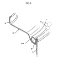
- a fourth embodiment of the balancer 20d is manufactured to have a quadrilateral cross section, similar to that of balancer 20b in FIG. 4 , and then all corners thereof are rounded. Thereby, the strength of the balancer 20C can be further increased.
- a method of manufacturing a balancer according to the present invention will be described with reference to FIGS. 7 through 12 .
- a linear metal pipe 22 used as material of the balancer 20 of the present invention is prepared.
- the linear metal pipe 22 is sized to be fitted into and coupled in the recess 15 of the spin tub 10 when bent in an annular shape.
- the linear metal pipe 22 is bent to have an annular shape, and then is filled with a plurality of balls 21 in a manner similar to that shown in FIG. 2 and a viscous fluid.
- the bent pipe 22 is welded at opposite ends thereof, so that the balancer 20a has a circular cross section.
- the plurality of balls 21 and the viscous fluid are held in the pipe 22 having a circular cross section in an airtight state, so that the balls 21 and fluid can act as the balancer.
- the annular pipe 22 having a circular cross section is pressed to have a quadrilateral cross section, thereby creating the balancer 20b.
- the balancer 20b formed to have the quadrilateral cross section can provide a space in which viscous fluid can flow to the corners thereof when the balls 21 move within the pipe 22, compared to the balancer 20a having the circular cross section of the same area, so that the spin tub 10 maintains a dynamic balance with rapidity. Further, the balancer 20b allows the balls 21 to move within the balancer 20b in a two-point contact state, so that the balls 21 make a stable motion.
- the balancer 20b is formed to have a quadrilateral cross section.
- the balancer 20b having the quadrilateral cross section may be varied in another structure by an additional formation, as illustrated in FIGS. 11 and 12 .
- the annular pipe 22 having the quadrilateral cross section can be formed such that at least one side thereof is curved.
- the balancer 20c provides an advantage in that the balls 21 can more stably move therein, in addition to the advantages of having the quadrilateral cross section.
- the annular pipe 22 having the quadrilateral cross section can be formed such that all corners thereof are rounded. Thereby, the strength of the balancer 20d can be further increased.
- the balancer has been described to be installed on a drum type washing machine by way of example, but it is apparent that the balancer can be applied to an upright type washing machine having a structure in which a spin tub is vertically installed.
- the balancer has mainly been described to have a circular cross section or a quadrilateral cross section, but it is not limited to such a cross section. Therefore, the balancer may have a variety of cross sections, as in polygons.
- the washing machine according to the present invention has a structure in which the balancer manufactured by forming a metal pipe in an annular shape is assembled to the spin tub, so that it can reduce a manufacturing cost and an assembly time to improve its mass productivity. Further, if the balancer is determined to fail after being assembled to the spin tub, the balancer can be rapidly and conveniently replaced with a new one, so that material costs may be reduced.
- the washing machine according to the present invention has a weld bead formed only at opposite ends of the bent pipe, so that a height difference between the opposite ends and the weld bead can be reduced to a minimum extent.
- the plurality of balls can smoothly move in the balancer, and the noise and vibration caused by the motion of the balls are hardly generated at all.
Landscapes
- Engineering & Computer Science (AREA)
- Textile Engineering (AREA)
- General Engineering & Computer Science (AREA)
- Physics & Mathematics (AREA)
- Acoustics & Sound (AREA)
- Aviation & Aerospace Engineering (AREA)
- Mechanical Engineering (AREA)
- Main Body Construction Of Washing Machines And Laundry Dryers (AREA)
Claims (9)
- Machine à laver comportant une cuve rotative (10) et un dispositif d'équilibrage (20) de forme annulaire, caractérisée en ce que
une extrémité avant et une extrémité arrière de la cuve rotative (10) sont ouvertes, et la cuve rotative (10) comprend un élément avant (12) et un élément arrière (13),
dans laquelle l'élément avant (12) et l'élément arrière (13) sont dotés d'un renfoncement annulaire (15), et dans laquelle le dispositif d'équilibrage (20) est placé dans le renfoncement (15) de l'élément avant (12) et/ou dans le renfoncement (15) de l'élément arrière (13), respectivement,
dans laquelle le dispositif d'équilibrage comporte un fluide visqueux et une pluralité de billes disposées et mobiles à l'intérieur d'un espace interne du dispositif d'équilibrage,
dans laquelle le dispositif d'équilibrage a une section transversale fournissant un espace quadrilatéral interne dans lequel le fluide visqueux peut s'écouler jusque dans des coins de celui-ci quand les billes se déplacent à l'intérieur du dispositif d'équilibrage durant la rotation de la cuve rotative, et
dans laquelle les coins internes de l'espace quadrilatère interne du dispositif d'équilibrage sont arrondis. - Machine à laver selon la revendication 1, dans laquelle l'élément avant (12) est doté d'une ouverture (14) permettant de placer le linge dans la cuve rotative (10) et de le retirer de celle-ci.
- Machine à laver selon la revendication 1 ou 2, dans laquelle l'élément arrière (13) est accouplé à un arbre rotatif (8) afin de faire tourner la cuve rotative (10).
- Machine à laver selon l'une quelconque des revendications précédentes, dans laquelle le renfoncement annulaire (15) de l'élément avant (12) est ouvert vers le devant de l'élément avant (12).
- Machine à laver selon l'une quelconque des revendications précédentes, dans laquelle le renfoncement annulaire (15) de l'élément arrière (13) est ouvert vers l'arrière de l'élément arrière (13).
- Machine à laver selon l'une quelconque des revendications précédentes, dans laquelle le dispositif d'équilibrage (20) est soudé dans le renfoncement annulaire (15) au niveau de plusieurs points dans le renfoncement (15).
- Machine à laver selon l'une quelconque des revendications précédentes, dans laquelle le dispositif d'équilibrage (20) comporte des extrémités ouvertes d'un tuyau (22) qui sont soudées ensemble.
- Machine à laver selon l'une quelconque des revendications précédentes, dans laquelle le dispositif d'équilibrage (20) comprend une pluralité de dispositifs d'équilibrage (20) accouplés à l'élément avant (12) et à l'élément arrière (13), la machine à laver étant une machine à laver du type à tambour, et l'au moins un renfoncement (15) comporte une pluralité de renfoncements (15), les renfoncements (15) étant aménagés au niveau des éléments avant et arrière (12, 13) de la cuve rotative (10) de telle sorte que les dispositifs d'équilibrage (20) soient accouplés à des extrémités opposées de la cuve rotative (10).
- Machine à laver selon la revendication 1, dans laquelle un côté du dispositif d'équilibrage (20) est courbe.
Applications Claiming Priority (2)
| Application Number | Priority Date | Filing Date | Title |
|---|---|---|---|
| KR1020060049477A KR101003352B1 (ko) | 2006-06-01 | 2006-06-01 | 밸런서를 구비한 세탁기 |
| KR1020060049481A KR101220216B1 (ko) | 2006-06-01 | 2006-06-01 | 세탁기의 밸런서 제작방법 |
Publications (4)
| Publication Number | Publication Date |
|---|---|
| EP1862576A2 EP1862576A2 (fr) | 2007-12-05 |
| EP1862576A3 EP1862576A3 (fr) | 2008-09-03 |
| EP1862576B1 EP1862576B1 (fr) | 2010-10-20 |
| EP1862576B3 true EP1862576B3 (fr) | 2012-01-18 |
Family
ID=38477137
Family Applications (1)
| Application Number | Title | Priority Date | Filing Date |
|---|---|---|---|
| EP07109106A Active EP1862576B3 (fr) | 2006-06-01 | 2007-05-29 | Machine à laver dotée d'un dispositif d'équilibrage et procédé de fabrication de son dispositif d'équilibrage |
Country Status (2)
| Country | Link |
|---|---|
| EP (1) | EP1862576B3 (fr) |
| DE (1) | DE602007009897D1 (fr) |
Families Citing this family (2)
| Publication number | Priority date | Publication date | Assignee | Title |
|---|---|---|---|---|
| KR102025781B1 (ko) | 2013-01-04 | 2019-11-04 | 삼성전자주식회사 | 밸런서 및 이를 구비하는 세탁기 |
| CN108791982B (zh) * | 2018-03-09 | 2024-05-14 | 浙江臻博精密机械有限公司 | 洗衣机平衡圈用盐水灌装系统及摩擦焊接设备 |
Family Cites Families (4)
| Publication number | Priority date | Publication date | Assignee | Title |
|---|---|---|---|---|
| US3321997A (en) * | 1965-01-14 | 1967-05-30 | Robert C Peterson | Load equalizer |
| SU1461796A1 (ru) * | 1987-03-25 | 1989-02-28 | Рижский политехнический институт им.А.Я.Пельше | Устройство балансировани центрифуги стиральной машины |
| US5870908A (en) * | 1997-09-18 | 1999-02-16 | Rushlow; Paul S. | Load balancing device |
| KR19990038279A (ko) | 1997-11-04 | 1999-06-05 | 구자홍 | 세탁기의 볼밸런서 |
-
2007
- 2007-05-29 EP EP07109106A patent/EP1862576B3/fr active Active
- 2007-05-29 DE DE602007009897T patent/DE602007009897D1/de active Active
Also Published As
| Publication number | Publication date |
|---|---|
| EP1862576A3 (fr) | 2008-09-03 |
| EP1862576A2 (fr) | 2007-12-05 |
| DE602007009897D1 (de) | 2010-12-02 |
| EP1862576B1 (fr) | 2010-10-20 |
Similar Documents
| Publication | Publication Date | Title |
|---|---|---|
| EP2436824B2 (fr) | Machine à laver dotée de compensateur | |
| EP1605088B1 (fr) | Machine à laver à tambour et tambour correspondant | |
| US5746069A (en) | Clothes washing machine having upper and lower dynamic balancers | |
| JPH1043475A (ja) | 洗濯機用ボールバランサ | |
| EP2377984A1 (fr) | Compensateur et machine à laver à tambour disposant de celui-ci | |
| US8857224B2 (en) | Washing machine having balancer and method of manufacturing balancer thereof | |
| EP1862576B1 (fr) | Machine à laver dotée d'un dispositif d'équilibrage et procédé de fabrication de son dispositif d'équilibrage | |
| KR101157835B1 (ko) | 밸런서를 구비한 세탁기 | |
| KR100423981B1 (ko) | 세탁기 | |
| US5870908A (en) | Load balancing device | |
| KR101220216B1 (ko) | 세탁기의 밸런서 제작방법 | |
| EP3702510B1 (fr) | Machine à laver le linge | |
| KR101219371B1 (ko) | 드럼세탁기 | |
| KR101220215B1 (ko) | 드럼세탁기 | |
| KR101397104B1 (ko) | 드럼 세탁기 |
Legal Events
| Date | Code | Title | Description |
|---|---|---|---|
| PUAI | Public reference made under article 153(3) epc to a published international application that has entered the european phase |
Free format text: ORIGINAL CODE: 0009012 |
|
| AK | Designated contracting states |
Kind code of ref document: A2 Designated state(s): AT BE BG CH CY CZ DE DK EE ES FI FR GB GR HU IE IS IT LI LT LU LV MC MT NL PL PT RO SE SI SK TR |
|
| AX | Request for extension of the european patent |
Extension state: AL BA HR MK YU |
|
| RIN1 | Information on inventor provided before grant (corrected) |
Inventor name: KIM, JA YOUNG Inventor name: RYU, DOO YOUNG Inventor name: MICHIAKI, ITO Inventor name: KANG, MYUNG SUN |
|
| PUAL | Search report despatched |
Free format text: ORIGINAL CODE: 0009013 |
|
| AK | Designated contracting states |
Kind code of ref document: A3 Designated state(s): AT BE BG CH CY CZ DE DK EE ES FI FR GB GR HU IE IS IT LI LT LU LV MC MT NL PL PT RO SE SI SK TR |
|
| AX | Request for extension of the european patent |
Extension state: AL BA HR MK RS |
|
| 17P | Request for examination filed |
Effective date: 20090213 |
|
| 17Q | First examination report despatched |
Effective date: 20090318 |
|
| AKX | Designation fees paid |
Designated state(s): DE FR GB |
|
| GRAP | Despatch of communication of intention to grant a patent |
Free format text: ORIGINAL CODE: EPIDOSNIGR1 |
|
| GRAS | Grant fee paid |
Free format text: ORIGINAL CODE: EPIDOSNIGR3 |
|
| GRAA | (expected) grant |
Free format text: ORIGINAL CODE: 0009210 |
|
| AK | Designated contracting states |
Kind code of ref document: B1 Designated state(s): DE FR GB |
|
| REG | Reference to a national code |
Ref country code: GB Ref legal event code: FG4D |
|
| REF | Corresponds to: |
Ref document number: 602007009897 Country of ref document: DE Date of ref document: 20101202 Kind code of ref document: P |
|
| PLCP | Request for limitation filed |
Free format text: ORIGINAL CODE: EPIDOSNLIM1 |
|
| REG | Reference to a national code |
Ref country code: DE Ref legal event code: R055 Ref document number: 602007009897 Country of ref document: DE |
|
| PLCQ | Request for limitation of patent found admissible |
Free format text: ORIGINAL CODE: 0009231 |
|
| LIM1 | Request for limitation found admissible |
Free format text: SEQUENCE NO: 1; FILED DURING OPPOSITION PERIOD Filing date: 20110301 |
|
| PLCO | Limitation procedure: reply received to communication from examining division + time limit |
Free format text: ORIGINAL CODE: EPIDOSNLIR3 |
|
| PLCR | Communication despatched that request for limitation of patent was allowed |
Free format text: ORIGINAL CODE: 0009245 |
|
| PLBE | No opposition filed within time limit |
Free format text: ORIGINAL CODE: 0009261 |
|
| 26N | No opposition filed |
Effective date: 20110721 |
|
| REG | Reference to a national code |
Ref country code: DE Ref legal event code: R056 Ref document number: 602007009897 Country of ref document: DE Effective date: 20110822 |
|
| REG | Reference to a national code |
Ref country code: DE Ref legal event code: R097 Ref document number: 602007009897 Country of ref document: DE Effective date: 20110721 |
|
| PLCN | Payment of fee for limitation of patent |
Free format text: ORIGINAL CODE: EPIDOSNRAL3 |
|
| PUAM | (expected) publication of b3 document |
Free format text: ORIGINAL CODE: 0009410 |
|
| STAA | Information on the status of an ep patent application or granted ep patent |
Free format text: STATUS: THE PATENT HAS BEEN LIMITED |
|
| REG | Reference to a national code |
Ref country code: FR Ref legal event code: PLFP Year of fee payment: 10 |
|
| REG | Reference to a national code |
Ref country code: FR Ref legal event code: PLFP Year of fee payment: 11 |
|
| REG | Reference to a national code |
Ref country code: FR Ref legal event code: PLFP Year of fee payment: 12 |
|
| PGFP | Annual fee paid to national office [announced via postgrant information from national office to epo] |
Ref country code: DE Payment date: 20250422 Year of fee payment: 19 |
|
| PGFP | Annual fee paid to national office [announced via postgrant information from national office to epo] |
Ref country code: FR Payment date: 20250422 Year of fee payment: 19 |
|
| PGFP | Annual fee paid to national office [announced via postgrant information from national office to epo] |
Ref country code: GB Payment date: 20260324 Year of fee payment: 20 |