EP1862688A2 - Agencement de transmission d'un couple de rotation pour le conducteur de commande d'un véhicule - Google Patents
Agencement de transmission d'un couple de rotation pour le conducteur de commande d'un véhicule Download PDFInfo
- Publication number
- EP1862688A2 EP1862688A2 EP07009901A EP07009901A EP1862688A2 EP 1862688 A2 EP1862688 A2 EP 1862688A2 EP 07009901 A EP07009901 A EP 07009901A EP 07009901 A EP07009901 A EP 07009901A EP 1862688 A2 EP1862688 A2 EP 1862688A2
- Authority
- EP
- European Patent Office
- Prior art keywords
- assembly
- pressure plate
- coupled
- rod
- plate
- Prior art date
- Legal status (The legal status is an assumption and is not a legal conclusion. Google has not performed a legal analysis and makes no representation as to the accuracy of the status listed.)
- Granted
Links
Images


Classifications
-
- F—MECHANICAL ENGINEERING; LIGHTING; HEATING; WEAPONS; BLASTING
- F16—ENGINEERING ELEMENTS AND UNITS; GENERAL MEASURES FOR PRODUCING AND MAINTAINING EFFECTIVE FUNCTIONING OF MACHINES OR INSTALLATIONS; THERMAL INSULATION IN GENERAL
- F16D—COUPLINGS FOR TRANSMITTING ROTATION; CLUTCHES; BRAKES
- F16D21/00—Systems comprising a plurality of actuated clutches
- F16D21/02—Systems comprising a plurality of actuated clutches for interconnecting three or more shafts or other transmission members in different ways
- F16D21/06—Systems comprising a plurality of actuated clutches for interconnecting three or more shafts or other transmission members in different ways at least two driving shafts or two driven shafts being concentric
-
- F—MECHANICAL ENGINEERING; LIGHTING; HEATING; WEAPONS; BLASTING
- F16—ENGINEERING ELEMENTS AND UNITS; GENERAL MEASURES FOR PRODUCING AND MAINTAINING EFFECTIVE FUNCTIONING OF MACHINES OR INSTALLATIONS; THERMAL INSULATION IN GENERAL
- F16D—COUPLINGS FOR TRANSMITTING ROTATION; CLUTCHES; BRAKES
- F16D21/00—Systems comprising a plurality of actuated clutches
-
- F—MECHANICAL ENGINEERING; LIGHTING; HEATING; WEAPONS; BLASTING
- F16—ENGINEERING ELEMENTS AND UNITS; GENERAL MEASURES FOR PRODUCING AND MAINTAINING EFFECTIVE FUNCTIONING OF MACHINES OR INSTALLATIONS; THERMAL INSULATION IN GENERAL
- F16D—COUPLINGS FOR TRANSMITTING ROTATION; CLUTCHES; BRAKES
- F16D25/00—Fluid-actuated clutches
- F16D25/08—Fluid-actuated clutches with fluid-actuated member not rotating with a clutching member
- F16D25/082—Fluid-actuated clutches with fluid-actuated member not rotating with a clutching member the line of action of the fluid-actuated members co-inciding with the axis of rotation
- F16D25/087—Fluid-actuated clutches with fluid-actuated member not rotating with a clutching member the line of action of the fluid-actuated members co-inciding with the axis of rotation the clutch being actuated by the fluid-actuated member via a diaphragm spring or an equivalent array of levers
-
- F—MECHANICAL ENGINEERING; LIGHTING; HEATING; WEAPONS; BLASTING
- F16—ENGINEERING ELEMENTS AND UNITS; GENERAL MEASURES FOR PRODUCING AND MAINTAINING EFFECTIVE FUNCTIONING OF MACHINES OR INSTALLATIONS; THERMAL INSULATION IN GENERAL
- F16D—COUPLINGS FOR TRANSMITTING ROTATION; CLUTCHES; BRAKES
- F16D21/00—Systems comprising a plurality of actuated clutches
- F16D21/02—Systems comprising a plurality of actuated clutches for interconnecting three or more shafts or other transmission members in different ways
- F16D21/06—Systems comprising a plurality of actuated clutches for interconnecting three or more shafts or other transmission members in different ways at least two driving shafts or two driven shafts being concentric
- F16D2021/0607—Double clutch with torque input plate in-between the two clutches, i.e. having a central input plate
- F16D2021/0615—Double clutch with torque input plate in-between the two clutches, i.e. having a central input plate the central input plate is supported by bearings in-between the two clutches
-
- F—MECHANICAL ENGINEERING; LIGHTING; HEATING; WEAPONS; BLASTING
- F16—ENGINEERING ELEMENTS AND UNITS; GENERAL MEASURES FOR PRODUCING AND MAINTAINING EFFECTIVE FUNCTIONING OF MACHINES OR INSTALLATIONS; THERMAL INSULATION IN GENERAL
- F16D—COUPLINGS FOR TRANSMITTING ROTATION; CLUTCHES; BRAKES
- F16D21/00—Systems comprising a plurality of actuated clutches
- F16D21/02—Systems comprising a plurality of actuated clutches for interconnecting three or more shafts or other transmission members in different ways
- F16D21/06—Systems comprising a plurality of actuated clutches for interconnecting three or more shafts or other transmission members in different ways at least two driving shafts or two driven shafts being concentric
- F16D2021/0684—Mechanically actuated clutches with two clutch plates
-
- F—MECHANICAL ENGINEERING; LIGHTING; HEATING; WEAPONS; BLASTING
- F16—ENGINEERING ELEMENTS AND UNITS; GENERAL MEASURES FOR PRODUCING AND MAINTAINING EFFECTIVE FUNCTIONING OF MACHINES OR INSTALLATIONS; THERMAL INSULATION IN GENERAL
- F16D—COUPLINGS FOR TRANSMITTING ROTATION; CLUTCHES; BRAKES
- F16D2300/00—Special features for couplings or clutches
- F16D2300/24—Concentric actuation rods, e.g. actuation rods extending concentrically through a shaft
Definitions
- the present invention relates to a torque transmission assembly for the powertrain of a vehicle, comprising a dual clutch assembly having a central abutment plate to be coupled or coupled to a drive member and a pressure plate assembly on both axial sides of the abutment plate, each pressure plate assembly defining or being fixed to the abutment plate Housing, a relative to the housing substantially rotatably and axially movable held pressure plate and supported with respect to the pressure plate and the housing Kraftbeaufhausungsan whatsoever further comprising in association with each pressure plate assembly coupled to a driven member or coupling coupling disc, which upon application of the pressure plate by the Kraftbeaufyerungsan ever can be pressed against the abutment plate, wherein the output members comprise two coaxially arranged output shafts and wherein in the coaxial inner output shaft, a rod-like actuator is arranged, via which an actuating force to the Kraftbeaufyerungsan ever that pressure plate assembly is transferable, whose associated clutch disc is coupled or to be coupled to the coaxial inner output shaft
- Such a torque transmission arrangement is known from DE 100 12 808 A1 known.
- the two arranged on both sides of a central abutment plate coupling portions of the dual clutch assembly of this known torque transmission arrangement are actuated by respective associated actuating systems. It is for the on the gearbox facing away from the double clutch assembly lying clutch region in the coaxially inner output shaft or transmission input shaft slidably disposed a rod-like actuator, which acts via a plate-like transmission element on the substantially designed as a plate spring Kraftbeaufschlagungsan ever.
- the Kraftbeaufschlagungsan ever or the plate spring is designed so that it is installed under bias between the pressure plate and the housing and moves the pressure plate towards the central abutment plate.
- a torque transmission arrangement for the drive train of a vehicle comprising a dual clutch assembly with a central abutment plate which is coupled or to be coupled to a drive member, and at both axial sides of the abutment plate each have a pressure plate assembly, each pressure plate assembly a fixed to the abutment plate or housing to be defined, a relative to the housing substantially rotationally fixed and axially movable held pressure application and supported with respect to the pressure plate and the housing Kraftbeaufhausungsan whatsoever further comprising in association with each pressure plate assembly coupled to a driven member or coupled coupling disc, which upon application of the pressure plate by the Kraftbeaufschlagungsan ever can be pressed against the abutment plate, wherein the output members arranged coaxially with each other Including output shafts and wherein in the coaxial inner output shaft, a rod-like actuator is arranged, via which an actuating force to the Kraftbeaufyerungsan ever that pressure plate assembly is transferable, the associated clutch disc is coupled or to
- the rod-like actuator is subject to a tensile load when transmitting an actuating force from the actuating system to the Kraftbeetzschungsaniser.
- the actuation system initiates the actuation force at the actuation end via a rotary decoupling bearing in the rod-like actuator.
- the rotational decoupling can also be realized by arranging a rotary decoupling bearing between the rod-like actuating member and the force application arrangement in the actuating force transmission path.
- the actuation system comprise an actuation lever which is supported in a first support area with respect to a substantially stationary module and which in an second support area initiates an actuation force into the rod-like actuation element.
- the actuating system it is also possible for the actuating system to comprise a piston / cylinder assembly which essentially surrounds the rod-like actuating member coaxially, which is supported relative to a substantially stationary assembly and acts on the rod-like actuating member to initiate an actuating force.
- the central abutment plate has a radially inner storage area in which it is mounted with respect to the coaxial outer shaft.
- the central abutment plate is held with its storage area with respect to the coaxial outer shaft axially substantially stationary. In this way, a defined axial positioning for the dual clutch assembly is provided and it can be ensured that actuating forces are supported within the actuating system or the dual clutch assembly itself and not be transmitted for example to the bearings of a crankshaft of a drive unit.
- the present invention relates to a torque train assembly for the powertrain of a vehicle, comprising a dual clutch assembly having a central abutment plate to be coupled or coupled to a drive member, and at both axial sides of the abutment plate each have a pressure plate assembly, each pressure plate assembly on the Enclosed plate fixed or fixed housing, a respect to the housing substantially rotatably and axially movable held pressure plate and supported with respect to the pressure plate and the housing Kraftbeaufhausungsan whatsoever further comprising in association with each pressure plate assembly coupled to a driven member or coupled coupling disc, which upon application of the Springs plate can be pressed by the Kraftbeaufyerungsan ever against the abutment plate.
- both pressure plate assemblies provide substantially the same functionalities and power relationships, which is advantageous in terms of the characteristics of the operations to be performed.
- a torque transmission assembly is generally designated 10.
- This torque transmission arrangement comprises two major system areas. One of these is a dual-clutch arrangement 12.
- the other of these system areas is a torsional vibration damper arrangement 14 designed in the form of a dual-mass flywheel.
- This is configured with a primary side 16, which in a radially inner area via a plurality of bolts 18 or the like to a drive member, for example a crankshaft an internal combustion engine, is rotatably coupled.
- the primary side 16 is essentially constructed with two cover disk elements 20, 22, between which a central disk element 24 of a secondary side 26 of the torsional vibration damper arrangement 14 engages.
- a damper element arrangement 28 comprising a plurality of damper springs acts on torques to be transmitted or occurring
- a non-illustrated friction arrangement may be provided so that when rotational nonuniformities occur also vibration energy can be dissipated in a defined extent by this friction.
- the dual clutch assembly 12 includes a central abutment plate 30 and on both axial sides - axially relative to a rotation axis A of the overall system - thereof each have a coupling portion 32, 34.
- the two coupling portions 32, 34 are preferably of substantially the same construction and only reversed to the central Abutment plate 30 connected.
- each of these coupling regions 32, 34 comprises a pressure plate assembly 36 and 38, respectively, with a substantially pot-like housing 40, 42. Radially outwardly, these two housings 40, 42 are fixedly connected to the abutment plate 30 by bolts, for example.
- a ring-shaped Veriereungselement 44 which is in mesh with a corresponding toothing element 46 on the central disk element 24 or engageable is.
- Each of the two coupling regions 32, 34 or each of the pressure plate assemblies 36, 38 further comprises a pressure plate 48, 50.
- These pressure plates 48, 50 may, for example, via tangential leaf springs or the like with the associated housing 40 or 42 or the abutment plate 30 rotatably, but be coupled axially movable.
- the coupling with the housings 40, 42 is preferred due to the provision of the pressure plate assemblies 36, 38 as preassembled assemblies.
- each of the pressure plate assemblies 36, 38 has a force application arrangement 52 and 54, respectively. These can in principle be constructed in the manner of a diaphragm spring and be integrated with a certain bias in the respective pressure plate assembly 36 and 38, respectively.
- Both Kraftbeetzleyungsan extract 52, 54 are axially supported in their radially outer region with respect to the respective associated housing 40, 42 and can act in a radially further inner region, for example via a respective wear compensation assembly 56, 58, the associated pressure plate 48, 50. Since in such a dual clutch assembly 12 generally only one of the coupling portions 32, 34 torque is to be transmitted, while the other coupling portion should be in a disengaged state, it is advantageous, the two coupling portions 32, 34 as so-called normal-open clutches embody. This can be realized by virtue of the fact that the two force application arrangements 52, 54 are in principle biased in the disengagement direction, ie in a direction in which they release the associated pressure plates 48, 50.
- a rod-like actuator 60 can be seen in association with the Kraftbeaufschlagungsan whatsoever 52 of the coupling portion 30 of this confirmation system, which extends in a central opening of the coaxial inner of two mutually coaxial transmission input shafts 62, 64 shown.
- the actuator 60 is at his 1 recognizable end firmly connected to a pot-like transmission element 66 which acts on movement of the confirmation element 60 in the illustration of FIG. 1 to the right, ie in the coaxial inner output shaft or transmission input shaft 64, the radially inner region of the Kraftbeaufschlagungsan für 52 and thus also the pressure plate 48 in the direction of the abutment plate 30 moves.
- the force application arrangement 54 of the pressure plate assembly 38 to be positioned in the illustration of FIG. 1 on the right, ie gear facing, is subjected to a rotary decoupling bearing 55 and an actuating system represented merely by a force arrow F 1 to carry out engagement processes.
- Each coupling region 32, 34 also has a clutch disk 68, 70 in association with the respective pressure plate assembly 36, 38.
- Each clutch disc has a radially outer friction region 72, 74, which is in each case between the central abutment plate 30 and the associated pressure plate 48 or 50 and thus between them can be clamped.
- Radially inside, the clutch plates 68, 70 each have a hub region 76, 78.
- the hub portion 76 of the clutch disc 68 is supported on the coaxially inner output shaft or transmission input shaft 64 and, as is common practice, provided with a toothing, which is in mesh with a corresponding toothing on the axial end of the output shaft 64 and thus a rotationally fixed coupling between the clutch disc 68 and this output shaft 64 realized, while still allowing relative axial movement.
- the hub portion 78 of the clutch disc 70 is on the coaxial outer output shaft via a toothing provided on this hub portion 78 in mesh with a corresponding toothing on this coaxially outer output shaft 62nd
- the central abutment plate 30 has a radially inner storage area 84.
- This storage area comprises an axially decoupled with the abutment plate 30 Wheelentkopplungslager 86 which between a fixed Axialschulsanschlag 88 on the abutment plate 30 and one at the Abutment plate 30 to be determined retaining ring 90 is axially locked.
- the rotary decoupling bearing 86 is further supported on the coaxial outer output shaft 62 in radially defined positioning, so that over this support portion 84, in particular the rotary decoupling bearing 86 thereof the abutment plate 30 is mounted on the coaxial outer output shaft 62.
- a further securing ring 92 secures the rotary decoupling bearing 86 and thus the entire abutment plate 30 in the axial direction on the coaxial outer output shaft 62.
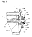
- FIG. 2 shows the end 100, which is remote from the dual clutch arrangement 12, of the rod-like actuating element 60, which protrudes beyond the rear side of a transmission or transmission housing, generally designated 102.
- the rod-like actuating element 60 is mounted via a sleeve-like bearing element 104 in the coaxially inner output shaft or transmission input shaft 64.
- a plate-like transmission element 108 is axially coupled to the actuating element 60 via a securing ring 106.
- a rotary decoupling bearing 110 is supported, on which in turn another annular transmission element 112 is axially supported. In its radially inner region of this transmission element 112 is supported on the rod-like actuator 60.
- An actuating lever 114 of an actuating system is pivotably mounted in an end region 116 on a button-like bearing element 118, which bearing element 118 is in turn carried on the gear 102 and on the gear housing. In a middle. Area, the actuating lever 114 has an opening 120 into which the transmission element 112 partially engages. The transmission element 112 has a radially outwardly gripping flange region 122, on which, when a pivoting movement is carried out, the actuating lever 114 comes into contact with its region surrounding the opening 120.
- the actuating lever 114 is acted upon in its second end region 124 by a force F 2 , for example by an axially displaceable tappet of an actuating system not further described in detail, it pivots clockwise and thereby presses the actuating element 112 against the rotary decoupling bearing 110 presses on the transmission element 108 against the rod-like actuator 60 so that it is pulled in the illustration of Figs. 1 and 2 to the right.
- the rod-like actuator 60 thereby pulls the radially inner end portion 53 of the Kraftbeetzleyungsan extract 52 towards the central abutment plate 30 via the transmission element 66, whereby the pressure plate 48 is moved toward this central abutment plate 30 to.
- FIG. 3 an alternative is shown in which at the end 100 of the rod-like actuating member 60, a piston / cylinder assembly 130 engages to pull to perform an actuating operation on this rod-like actuator 100.
- a cylinder member 132 of this piston / cylinder assembly 130 is supported at the rear end of the transmission 102 and has an annular cylinder chamber 134, for example.
- a correspondingly ring-like piston 136 is guided in the longitudinal direction of the rod-like actuating element 100 slidably.
- pressure fluid can be introduced into the cylinder chamber 134 so as to force the piston 136 out of the cylinder chamber 134 in order to carry out an actuating operation and thus pull the rod-like actuating element 60 via the rotary decoupling bearing 110.
- the two coupling regions 32, 34 or their pressure plate assemblies 36, 38 can be configured essentially identical to one another. They are set only in opposite manner on the two sides of the central abutment plate 30. On the housing 40 of the Torsionsschwingungsdämpferanowski 30 facing pressure plate assembly can then continue the ring-like element 44 are determined. Otherwise, however, the two printing plate assemblies 36, 38 may be substantially identical or identical, resulting in a much more cost-effective structure due to a smaller number of parts leads.
Landscapes
- Engineering & Computer Science (AREA)
- General Engineering & Computer Science (AREA)
- Mechanical Engineering (AREA)
- Mechanical Operated Clutches (AREA)
- Hydraulic Clutches, Magnetic Clutches, Fluid Clutches, And Fluid Joints (AREA)
Applications Claiming Priority (1)
| Application Number | Priority Date | Filing Date | Title |
|---|---|---|---|
| DE102006025529A DE102006025529A1 (de) | 2006-06-01 | 2006-06-01 | Drehmomentübertragungsanordnung für den Antriebsstrang eines Fahrzeugs |
Publications (4)
| Publication Number | Publication Date |
|---|---|
| EP1862688A2 true EP1862688A2 (fr) | 2007-12-05 |
| EP1862688A3 EP1862688A3 (fr) | 2010-06-16 |
| EP1862688B1 EP1862688B1 (fr) | 2011-07-27 |
| EP1862688B2 EP1862688B2 (fr) | 2018-08-08 |
Family
ID=38461013
Family Applications (1)
| Application Number | Title | Priority Date | Filing Date |
|---|---|---|---|
| EP07009901.5A Not-in-force EP1862688B2 (fr) | 2006-06-01 | 2007-05-18 | Agencement de transmission d'un couple de rotation pour le conducteur de commande d'un véhicule |
Country Status (3)
| Country | Link |
|---|---|
| EP (1) | EP1862688B2 (fr) |
| AT (1) | ATE518071T1 (fr) |
| DE (1) | DE102006025529A1 (fr) |
Cited By (2)
| Publication number | Priority date | Publication date | Assignee | Title |
|---|---|---|---|---|
| DE102011104247A1 (de) | 2010-06-29 | 2011-12-29 | Schaeffler Technologies Gmbh & Co. Kg | Doppelkupplungsanordnung |
| CN104728297A (zh) * | 2013-12-18 | 2015-06-24 | 舍弗勒技术有限两合公司 | 用于轴向双离合器的驱动隔板 |
Families Citing this family (3)
| Publication number | Priority date | Publication date | Assignee | Title |
|---|---|---|---|---|
| FR2959542B1 (fr) | 2010-04-28 | 2012-04-27 | Valeo Embrayages | Double embrayage, notamment pour vehicule automobile |
| DE102012220438A1 (de) * | 2011-11-30 | 2013-06-06 | Schaeffler Technologies AG & Co. KG | Anordnung einer kleinen Doppelkupplung |
| US9291210B2 (en) | 2014-08-11 | 2016-03-22 | GM Global Technology Operations LLC | Flywheel and dual clutch module assembly |
Family Cites Families (14)
| Publication number | Priority date | Publication date | Assignee | Title |
|---|---|---|---|---|
| FR88126E (fr) * | 1965-04-28 | 1966-04-15 | Ferodo Sa | Perfectionnements aux embrayages à sorties multiples |
| DE2211521A1 (de) † | 1972-03-10 | 1973-09-13 | Volkswagenwerk Ag | Vorrichtung zur mechanischen kupplungsbetaetigung, insbesondere fuer kraftfahrzeugkupplungen |
| DE2824682A1 (de) * | 1978-06-06 | 1979-12-20 | Luk Lamellen & Kupplungsbau | Verfahren und einrichtung zum betrieb einer brennkraftmaschine mit dieser nachgeschalteter schwungmasse |
| US4287977A (en) † | 1978-10-28 | 1981-09-08 | Toyota Jidosha Kogyo Kabushiki Kaisha | Hydraulic clutch release mechanism |
| DE3023294A1 (de) † | 1980-06-21 | 1982-01-07 | Fichtel & Sachs Ag, 8720 Schweinfurt | Schwungradkupplung |
| DE3037990A1 (de) † | 1980-10-08 | 1982-05-13 | Volkswagenwerk Ag, 3180 Wolfsburg | Zahnraedergetriebe |
| JPS58639A (ja) † | 1981-06-23 | 1983-01-05 | Honda Motor Co Ltd | クラツチのレリ−ズ装置 |
| DE10012807A1 (de) † | 2000-03-16 | 2001-09-20 | Mannesmann Sachs Ag | Betätigungsanordnung für eine Reibungskupplungsanordnung |
| DE10012808A1 (de) * | 2000-03-16 | 2001-09-20 | Mannesmann Sachs Ag | Doppelkupplungsanordnung |
| FR2807481B1 (fr) † | 2000-04-10 | 2002-08-02 | Peugeot Citroen Automobiles Sa | Dispositif d'embrayage compact associe a une boite de vitesses comportant deux arbres primaires |
| DE10044493B4 (de) † | 2000-09-08 | 2012-05-03 | Zf Sachs Ag | Mehrfach-Kupplungseinrichtung, insbesondere Doppel-Kupplungseinrichtung, für lastschaltbare Getriebe |
| FR2814516B1 (fr) † | 2000-09-22 | 2003-05-02 | Valeo | Dispositif de transmission a engrenages, en particulier pour vehicule automobile |
| ITTO20020382A1 (it) † | 2002-05-08 | 2003-11-10 | Fiat Ricerche | Trasmissione automobilistica. |
| DE102005037514B4 (de) † | 2004-09-03 | 2021-09-30 | Schaeffler Technologies AG & Co. KG | Drehmomentübertragungseinrichtung |
-
2006
- 2006-06-01 DE DE102006025529A patent/DE102006025529A1/de not_active Withdrawn
-
2007
- 2007-05-18 EP EP07009901.5A patent/EP1862688B2/fr not_active Not-in-force
- 2007-05-18 AT AT07009901T patent/ATE518071T1/de active
Cited By (2)
| Publication number | Priority date | Publication date | Assignee | Title |
|---|---|---|---|---|
| DE102011104247A1 (de) | 2010-06-29 | 2011-12-29 | Schaeffler Technologies Gmbh & Co. Kg | Doppelkupplungsanordnung |
| CN104728297A (zh) * | 2013-12-18 | 2015-06-24 | 舍弗勒技术有限两合公司 | 用于轴向双离合器的驱动隔板 |
Also Published As
| Publication number | Publication date |
|---|---|
| EP1862688A3 (fr) | 2010-06-16 |
| EP1862688B2 (fr) | 2018-08-08 |
| DE102006025529A1 (de) | 2007-12-06 |
| EP1862688B1 (fr) | 2011-07-27 |
| ATE518071T1 (de) | 2011-08-15 |
Similar Documents
| Publication | Publication Date | Title |
|---|---|---|
| EP2494225B1 (fr) | Module d'embrayage | |
| EP1988302B1 (fr) | Embrayage double | |
| EP3069037B1 (fr) | Ensemble embrayage | |
| EP1430230B1 (fr) | Systeme a plusieurs embrayages, en particulier a double embrayage | |
| DE102010054545A1 (de) | Drehmomentübertragungseinrichtung | |
| EP1134447B1 (fr) | Configuration de double embrayage | |
| DE10016607B4 (de) | Doppelkupplungsanordnung | |
| EP2326852B1 (fr) | Ligne d'entraînement avec double embrayage | |
| EP1862688B1 (fr) | Agencement de transmission d'un couple de rotation pour le conducteur de commande d'un véhicule | |
| EP3123043A2 (fr) | Double embrayage à disques multiples | |
| EP1862685A1 (fr) | Agencement de transmission d'un couple de rotation pour le conducteur de commande d'un véhicule | |
| DE102012213684A1 (de) | Zugankeranordnung zum Verlagern einer Anpressplatte einer Reibungskupplung | |
| WO2010149130A2 (fr) | Double embrayage | |
| DE10348312A1 (de) | Betätigungseinrichtung für eine Reibungskupplungseinrichtung, ggf. Doppel- oder Mehrfach-Reibungskupplungseinrichtung | |
| EP1862687A2 (fr) | Agencement de transmission d'un couple de rotation pour ligne de transmission de véhicule | |
| EP3161340A1 (fr) | Embrayage double multidisques humide comportant des leviers dans l'espace humide | |
| DE10329194A1 (de) | Drehmomentübertragungssystem für einen Fahrzeugantriebsstrang | |
| DE102017126799A1 (de) | Selbstverstärkende Reibungskupplung mit Blattfedern | |
| DE102021108408B3 (de) | Trennkupplung für Hybridmodul, und Hybridmodul | |
| DE102021108418B4 (de) | Trennkupplung für Hybridmodul, und Hybridmodul | |
| EP1916435B1 (fr) | Système d'embrayage | |
| DE10201914B4 (de) | Reibungskupplung | |
| WO2019001638A1 (fr) | Dispositif d'accouplement | |
| EP3601830A1 (fr) | Dispositif d'embrayage pour une chaîne cinématique d'un véhicule | |
| DE10234548A1 (de) | Mehrfach-Kupplungsanordnung, insbesondere Doppelkupplungsanordnung |
Legal Events
| Date | Code | Title | Description |
|---|---|---|---|
| PUAI | Public reference made under article 153(3) epc to a published international application that has entered the european phase |
Free format text: ORIGINAL CODE: 0009012 |
|
| AK | Designated contracting states |
Kind code of ref document: A2 Designated state(s): AT BE BG CH CY CZ DE DK EE ES FI FR GB GR HU IE IS IT LI LT LU LV MC MT NL PL PT RO SE SI SK TR |
|
| AX | Request for extension of the european patent |
Extension state: AL BA HR MK YU |
|
| PUAL | Search report despatched |
Free format text: ORIGINAL CODE: 0009013 |
|
| AK | Designated contracting states |
Kind code of ref document: A3 Designated state(s): AT BE BG CH CY CZ DE DK EE ES FI FR GB GR HU IE IS IT LI LT LU LV MC MT NL PL PT RO SE SI SK TR |
|
| AX | Request for extension of the european patent |
Extension state: AL BA HR MK RS |
|
| 17P | Request for examination filed |
Effective date: 20101207 |
|
| AKX | Designation fees paid |
Designated state(s): AT BE BG CH CY CZ DE DK EE ES FI FR GB GR HU IE IS IT LI LT LU LV MC MT NL PL PT RO SE SI SK TR |
|
| GRAP | Despatch of communication of intention to grant a patent |
Free format text: ORIGINAL CODE: EPIDOSNIGR1 |
|
| RIC1 | Information provided on ipc code assigned before grant |
Ipc: F16D 21/06 20060101AFI20110131BHEP |
|
| GRAS | Grant fee paid |
Free format text: ORIGINAL CODE: EPIDOSNIGR3 |
|
| GRAA | (expected) grant |
Free format text: ORIGINAL CODE: 0009210 |
|
| AK | Designated contracting states |
Kind code of ref document: B1 Designated state(s): AT BE BG CH CY CZ DE DK EE ES FI FR GB GR HU IE IS IT LI LT LU LV MC MT NL PL PT RO SE SI SK TR |
|
| REG | Reference to a national code |
Ref country code: GB Ref legal event code: FG4D Free format text: NOT ENGLISH |
|
| REG | Reference to a national code |
Ref country code: CH Ref legal event code: EP |
|
| REG | Reference to a national code |
Ref country code: DE Ref legal event code: R096 Ref document number: 502007007758 Country of ref document: DE Effective date: 20110915 |
|
| REG | Reference to a national code |
Ref country code: NL Ref legal event code: VDEP Effective date: 20110727 |
|
| PG25 | Lapsed in a contracting state [announced via postgrant information from national office to epo] |
Ref country code: FI Free format text: LAPSE BECAUSE OF FAILURE TO SUBMIT A TRANSLATION OF THE DESCRIPTION OR TO PAY THE FEE WITHIN THE PRESCRIBED TIME-LIMIT Effective date: 20110727 Ref country code: LT Free format text: LAPSE BECAUSE OF FAILURE TO SUBMIT A TRANSLATION OF THE DESCRIPTION OR TO PAY THE FEE WITHIN THE PRESCRIBED TIME-LIMIT Effective date: 20110727 Ref country code: PT Free format text: LAPSE BECAUSE OF FAILURE TO SUBMIT A TRANSLATION OF THE DESCRIPTION OR TO PAY THE FEE WITHIN THE PRESCRIBED TIME-LIMIT Effective date: 20111128 Ref country code: NL Free format text: LAPSE BECAUSE OF FAILURE TO SUBMIT A TRANSLATION OF THE DESCRIPTION OR TO PAY THE FEE WITHIN THE PRESCRIBED TIME-LIMIT Effective date: 20110727 Ref country code: SE Free format text: LAPSE BECAUSE OF FAILURE TO SUBMIT A TRANSLATION OF THE DESCRIPTION OR TO PAY THE FEE WITHIN THE PRESCRIBED TIME-LIMIT Effective date: 20110727 Ref country code: IS Free format text: LAPSE BECAUSE OF FAILURE TO SUBMIT A TRANSLATION OF THE DESCRIPTION OR TO PAY THE FEE WITHIN THE PRESCRIBED TIME-LIMIT Effective date: 20111127 |
|
| PG25 | Lapsed in a contracting state [announced via postgrant information from national office to epo] |
Ref country code: CY Free format text: LAPSE BECAUSE OF FAILURE TO SUBMIT A TRANSLATION OF THE DESCRIPTION OR TO PAY THE FEE WITHIN THE PRESCRIBED TIME-LIMIT Effective date: 20110727 Ref country code: GR Free format text: LAPSE BECAUSE OF FAILURE TO SUBMIT A TRANSLATION OF THE DESCRIPTION OR TO PAY THE FEE WITHIN THE PRESCRIBED TIME-LIMIT Effective date: 20111028 Ref country code: LV Free format text: LAPSE BECAUSE OF FAILURE TO SUBMIT A TRANSLATION OF THE DESCRIPTION OR TO PAY THE FEE WITHIN THE PRESCRIBED TIME-LIMIT Effective date: 20110727 Ref country code: PL Free format text: LAPSE BECAUSE OF FAILURE TO SUBMIT A TRANSLATION OF THE DESCRIPTION OR TO PAY THE FEE WITHIN THE PRESCRIBED TIME-LIMIT Effective date: 20110727 Ref country code: SI Free format text: LAPSE BECAUSE OF FAILURE TO SUBMIT A TRANSLATION OF THE DESCRIPTION OR TO PAY THE FEE WITHIN THE PRESCRIBED TIME-LIMIT Effective date: 20110727 |
|
| REG | Reference to a national code |
Ref country code: IE Ref legal event code: FD4D |
|
| PG25 | Lapsed in a contracting state [announced via postgrant information from national office to epo] |
Ref country code: CZ Free format text: LAPSE BECAUSE OF FAILURE TO SUBMIT A TRANSLATION OF THE DESCRIPTION OR TO PAY THE FEE WITHIN THE PRESCRIBED TIME-LIMIT Effective date: 20110727 Ref country code: SK Free format text: LAPSE BECAUSE OF FAILURE TO SUBMIT A TRANSLATION OF THE DESCRIPTION OR TO PAY THE FEE WITHIN THE PRESCRIBED TIME-LIMIT Effective date: 20110727 Ref country code: IE Free format text: LAPSE BECAUSE OF FAILURE TO SUBMIT A TRANSLATION OF THE DESCRIPTION OR TO PAY THE FEE WITHIN THE PRESCRIBED TIME-LIMIT Effective date: 20110727 |
|
| PLBI | Opposition filed |
Free format text: ORIGINAL CODE: 0009260 |
|
| PG25 | Lapsed in a contracting state [announced via postgrant information from national office to epo] |
Ref country code: RO Free format text: LAPSE BECAUSE OF FAILURE TO SUBMIT A TRANSLATION OF THE DESCRIPTION OR TO PAY THE FEE WITHIN THE PRESCRIBED TIME-LIMIT Effective date: 20110727 Ref country code: EE Free format text: LAPSE BECAUSE OF FAILURE TO SUBMIT A TRANSLATION OF THE DESCRIPTION OR TO PAY THE FEE WITHIN THE PRESCRIBED TIME-LIMIT Effective date: 20110727 Ref country code: IT Free format text: LAPSE BECAUSE OF FAILURE TO SUBMIT A TRANSLATION OF THE DESCRIPTION OR TO PAY THE FEE WITHIN THE PRESCRIBED TIME-LIMIT Effective date: 20110727 |
|
| PLAX | Notice of opposition and request to file observation + time limit sent |
Free format text: ORIGINAL CODE: EPIDOSNOBS2 |
|
| 26 | Opposition filed |
Opponent name: SCHAEFFLER TECHNOLOGIES AG & CO. KG Effective date: 20120427 |
|
| PG25 | Lapsed in a contracting state [announced via postgrant information from national office to epo] |
Ref country code: DK Free format text: LAPSE BECAUSE OF FAILURE TO SUBMIT A TRANSLATION OF THE DESCRIPTION OR TO PAY THE FEE WITHIN THE PRESCRIBED TIME-LIMIT Effective date: 20110727 |
|
| REG | Reference to a national code |
Ref country code: DE Ref legal event code: R026 Ref document number: 502007007758 Country of ref document: DE Effective date: 20120427 |
|
| PLAF | Information modified related to communication of a notice of opposition and request to file observations + time limit |
Free format text: ORIGINAL CODE: EPIDOSCOBS2 |
|
| PLBB | Reply of patent proprietor to notice(s) of opposition received |
Free format text: ORIGINAL CODE: EPIDOSNOBS3 |
|
| BERE | Be: lapsed |
Owner name: ZF FRIEDRICHSHAFEN A.G. Effective date: 20120531 |
|
| PG25 | Lapsed in a contracting state [announced via postgrant information from national office to epo] |
Ref country code: MC Free format text: LAPSE BECAUSE OF NON-PAYMENT OF DUE FEES Effective date: 20120531 |
|
| REG | Reference to a national code |
Ref country code: CH Ref legal event code: PL |
|
| GBPC | Gb: european patent ceased through non-payment of renewal fee |
Effective date: 20120518 |
|
| PG25 | Lapsed in a contracting state [announced via postgrant information from national office to epo] |
Ref country code: CH Free format text: LAPSE BECAUSE OF NON-PAYMENT OF DUE FEES Effective date: 20120531 Ref country code: LI Free format text: LAPSE BECAUSE OF NON-PAYMENT OF DUE FEES Effective date: 20120531 |
|
| PG25 | Lapsed in a contracting state [announced via postgrant information from national office to epo] |
Ref country code: BE Free format text: LAPSE BECAUSE OF NON-PAYMENT OF DUE FEES Effective date: 20120531 |
|
| PG25 | Lapsed in a contracting state [announced via postgrant information from national office to epo] |
Ref country code: ES Free format text: LAPSE BECAUSE OF FAILURE TO SUBMIT A TRANSLATION OF THE DESCRIPTION OR TO PAY THE FEE WITHIN THE PRESCRIBED TIME-LIMIT Effective date: 20111107 Ref country code: GB Free format text: LAPSE BECAUSE OF NON-PAYMENT OF DUE FEES Effective date: 20120518 |
|
| PG25 | Lapsed in a contracting state [announced via postgrant information from national office to epo] |
Ref country code: BG Free format text: LAPSE BECAUSE OF FAILURE TO SUBMIT A TRANSLATION OF THE DESCRIPTION OR TO PAY THE FEE WITHIN THE PRESCRIBED TIME-LIMIT Effective date: 20111027 |
|
| REG | Reference to a national code |
Ref country code: AT Ref legal event code: MM01 Ref document number: 518071 Country of ref document: AT Kind code of ref document: T Effective date: 20120518 |
|
| PG25 | Lapsed in a contracting state [announced via postgrant information from national office to epo] |
Ref country code: AT Free format text: LAPSE BECAUSE OF NON-PAYMENT OF DUE FEES Effective date: 20120518 Ref country code: MT Free format text: LAPSE BECAUSE OF FAILURE TO SUBMIT A TRANSLATION OF THE DESCRIPTION OR TO PAY THE FEE WITHIN THE PRESCRIBED TIME-LIMIT Effective date: 20110727 |
|
| PLAB | Opposition data, opponent's data or that of the opponent's representative modified |
Free format text: ORIGINAL CODE: 0009299OPPO |
|
| R26 | Opposition filed (corrected) |
Opponent name: SCHAEFFLER TECHNOLOGIES AG & CO. KG Effective date: 20120427 |
|
| PLAB | Opposition data, opponent's data or that of the opponent's representative modified |
Free format text: ORIGINAL CODE: 0009299OPPO |
|
| R26 | Opposition filed (corrected) |
Opponent name: SCHAEFFLER TECHNOLOGIES GMBH & CO. KG Effective date: 20120427 |
|
| PG25 | Lapsed in a contracting state [announced via postgrant information from national office to epo] |
Ref country code: TR Free format text: LAPSE BECAUSE OF FAILURE TO SUBMIT A TRANSLATION OF THE DESCRIPTION OR TO PAY THE FEE WITHIN THE PRESCRIBED TIME-LIMIT Effective date: 20110727 |
|
| APBM | Appeal reference recorded |
Free format text: ORIGINAL CODE: EPIDOSNREFNO |
|
| APBP | Date of receipt of notice of appeal recorded |
Free format text: ORIGINAL CODE: EPIDOSNNOA2O |
|
| APAH | Appeal reference modified |
Free format text: ORIGINAL CODE: EPIDOSCREFNO |
|
| APBM | Appeal reference recorded |
Free format text: ORIGINAL CODE: EPIDOSNREFNO |
|
| APBP | Date of receipt of notice of appeal recorded |
Free format text: ORIGINAL CODE: EPIDOSNNOA2O |
|
| PG25 | Lapsed in a contracting state [announced via postgrant information from national office to epo] |
Ref country code: LU Free format text: LAPSE BECAUSE OF NON-PAYMENT OF DUE FEES Effective date: 20120518 |
|
| APBQ | Date of receipt of statement of grounds of appeal recorded |
Free format text: ORIGINAL CODE: EPIDOSNNOA3O |
|
| APBQ | Date of receipt of statement of grounds of appeal recorded |
Free format text: ORIGINAL CODE: EPIDOSNNOA3O |
|
| PG25 | Lapsed in a contracting state [announced via postgrant information from national office to epo] |
Ref country code: HU Free format text: LAPSE BECAUSE OF FAILURE TO SUBMIT A TRANSLATION OF THE DESCRIPTION OR TO PAY THE FEE WITHIN THE PRESCRIBED TIME-LIMIT Effective date: 20070518 |
|
| REG | Reference to a national code |
Ref country code: FR Ref legal event code: PLFP Year of fee payment: 10 |
|
| PGFP | Annual fee paid to national office [announced via postgrant information from national office to epo] |
Ref country code: FR Payment date: 20160412 Year of fee payment: 10 |
|
| APBU | Appeal procedure closed |
Free format text: ORIGINAL CODE: EPIDOSNNOA9O |
|
| REG | Reference to a national code |
Ref country code: FR Ref legal event code: ST Effective date: 20180131 |
|
| PG25 | Lapsed in a contracting state [announced via postgrant information from national office to epo] |
Ref country code: FR Free format text: LAPSE BECAUSE OF NON-PAYMENT OF DUE FEES Effective date: 20170531 |
|
| PUAH | Patent maintained in amended form |
Free format text: ORIGINAL CODE: 0009272 |
|
| STAA | Information on the status of an ep patent application or granted ep patent |
Free format text: STATUS: PATENT MAINTAINED AS AMENDED |
|
| 27A | Patent maintained in amended form |
Effective date: 20180808 |
|
| AK | Designated contracting states |
Kind code of ref document: B2 Designated state(s): AT BE BG CH CY CZ DE DK EE ES FI FR GB GR HU IE IS IT LI LT LU LV MC MT NL PL PT RO SE SI SK TR |
|
| REG | Reference to a national code |
Ref country code: DE Ref legal event code: R102 Ref document number: 502007007758 Country of ref document: DE |
|
| PGFP | Annual fee paid to national office [announced via postgrant information from national office to epo] |
Ref country code: DE Payment date: 20190508 Year of fee payment: 13 |
|
| REG | Reference to a national code |
Ref country code: DE Ref legal event code: R119 Ref document number: 502007007758 Country of ref document: DE |
|
| PG25 | Lapsed in a contracting state [announced via postgrant information from national office to epo] |
Ref country code: DE Free format text: LAPSE BECAUSE OF NON-PAYMENT OF DUE FEES Effective date: 20201201 |