EP1862830A2 - Multiportkoppler, optischer Verstärker und Faserlaser - Google Patents
Multiportkoppler, optischer Verstärker und Faserlaser Download PDFInfo
- Publication number
- EP1862830A2 EP1862830A2 EP20070252215 EP07252215A EP1862830A2 EP 1862830 A2 EP1862830 A2 EP 1862830A2 EP 20070252215 EP20070252215 EP 20070252215 EP 07252215 A EP07252215 A EP 07252215A EP 1862830 A2 EP1862830 A2 EP 1862830A2
- Authority
- EP
- European Patent Office
- Prior art keywords
- fiber
- emitted light
- core
- cladding
- pumping
- Prior art date
- Legal status (The legal status is an assumption and is not a legal conclusion. Google has not performed a legal analysis and makes no representation as to the accuracy of the status listed.)
- Granted
Links
Images



Classifications
-
- G—PHYSICS
- G02—OPTICS
- G02B—OPTICAL ELEMENTS, SYSTEMS OR APPARATUS
- G02B6/00—Light guides; Structural details of arrangements comprising light guides and other optical elements, e.g. couplings
- G02B6/24—Coupling light guides
- G02B6/26—Optical coupling means
- G02B6/28—Optical coupling means having data bus means, i.e. plural waveguides interconnected and providing an inherently bidirectional system by mixing and splitting signals
- G02B6/2804—Optical coupling means having data bus means, i.e. plural waveguides interconnected and providing an inherently bidirectional system by mixing and splitting signals forming multipart couplers without wavelength selective elements, e.g. "T" couplers, star couplers
- G02B6/2821—Optical coupling means having data bus means, i.e. plural waveguides interconnected and providing an inherently bidirectional system by mixing and splitting signals forming multipart couplers without wavelength selective elements, e.g. "T" couplers, star couplers using lateral coupling between contiguous fibres to split or combine optical signals
- G02B6/2835—Optical coupling means having data bus means, i.e. plural waveguides interconnected and providing an inherently bidirectional system by mixing and splitting signals forming multipart couplers without wavelength selective elements, e.g. "T" couplers, star couplers using lateral coupling between contiguous fibres to split or combine optical signals formed or shaped by thermal treatment, e.g. couplers
-
- H—ELECTRICITY
- H01—ELECTRIC ELEMENTS
- H01S—DEVICES USING THE PROCESS OF LIGHT AMPLIFICATION BY STIMULATED EMISSION OF RADIATION [LASER] TO AMPLIFY OR GENERATE LIGHT; DEVICES USING STIMULATED EMISSION OF ELECTROMAGNETIC RADIATION IN WAVE RANGES OTHER THAN OPTICAL
- H01S3/00—Lasers, i.e. devices using stimulated emission of electromagnetic radiation in the infrared, visible or ultraviolet wave range
- H01S3/05—Construction or shape of optical resonators; Accommodation of active medium therein; Shape of active medium
- H01S3/06—Construction or shape of active medium
- H01S3/063—Waveguide lasers, i.e. whereby the dimensions of the waveguide are of the order of the light wavelength
- H01S3/067—Fibre lasers
- H01S3/06708—Constructional details of the fibre, e.g. compositions, cross-section, shape or tapering
- H01S3/06729—Peculiar transverse fibre profile
-
- H—ELECTRICITY
- H01—ELECTRIC ELEMENTS
- H01S—DEVICES USING THE PROCESS OF LIGHT AMPLIFICATION BY STIMULATED EMISSION OF RADIATION [LASER] TO AMPLIFY OR GENERATE LIGHT; DEVICES USING STIMULATED EMISSION OF ELECTROMAGNETIC RADIATION IN WAVE RANGES OTHER THAN OPTICAL
- H01S3/00—Lasers, i.e. devices using stimulated emission of electromagnetic radiation in the infrared, visible or ultraviolet wave range
- H01S3/09—Processes or apparatus for excitation, e.g. pumping
- H01S3/091—Processes or apparatus for excitation, e.g. pumping using optical pumping
- H01S3/094—Processes or apparatus for excitation, e.g. pumping using optical pumping by coherent light
- H01S3/094003—Processes or apparatus for excitation, e.g. pumping using optical pumping by coherent light the pumped medium being a fibre
- H01S3/094007—Cladding pumping, i.e. pump light propagating in a clad surrounding the active core
-
- H—ELECTRICITY
- H01—ELECTRIC ELEMENTS
- H01S—DEVICES USING THE PROCESS OF LIGHT AMPLIFICATION BY STIMULATED EMISSION OF RADIATION [LASER] TO AMPLIFY OR GENERATE LIGHT; DEVICES USING STIMULATED EMISSION OF ELECTROMAGNETIC RADIATION IN WAVE RANGES OTHER THAN OPTICAL
- H01S3/00—Lasers, i.e. devices using stimulated emission of electromagnetic radiation in the infrared, visible or ultraviolet wave range
- H01S3/09—Processes or apparatus for excitation, e.g. pumping
- H01S3/091—Processes or apparatus for excitation, e.g. pumping using optical pumping
- H01S3/094—Processes or apparatus for excitation, e.g. pumping using optical pumping by coherent light
- H01S3/094003—Processes or apparatus for excitation, e.g. pumping using optical pumping by coherent light the pumped medium being a fibre
- H01S3/094015—Processes or apparatus for excitation, e.g. pumping using optical pumping by coherent light the pumped medium being a fibre with pump light recycling, i.e. with reinjection of the unused pump light back into the fiber, e.g. by reflectors or circulators
-
- H—ELECTRICITY
- H01—ELECTRIC ELEMENTS
- H01S—DEVICES USING THE PROCESS OF LIGHT AMPLIFICATION BY STIMULATED EMISSION OF RADIATION [LASER] TO AMPLIFY OR GENERATE LIGHT; DEVICES USING STIMULATED EMISSION OF ELECTROMAGNETIC RADIATION IN WAVE RANGES OTHER THAN OPTICAL
- H01S3/00—Lasers, i.e. devices using stimulated emission of electromagnetic radiation in the infrared, visible or ultraviolet wave range
- H01S3/09—Processes or apparatus for excitation, e.g. pumping
- H01S3/091—Processes or apparatus for excitation, e.g. pumping using optical pumping
- H01S3/094—Processes or apparatus for excitation, e.g. pumping using optical pumping by coherent light
- H01S3/094049—Guiding of the pump light
- H01S3/094053—Fibre coupled pump, e.g. delivering pump light using a fibre or a fibre bundle
-
- H—ELECTRICITY
- H01—ELECTRIC ELEMENTS
- H01S—DEVICES USING THE PROCESS OF LIGHT AMPLIFICATION BY STIMULATED EMISSION OF RADIATION [LASER] TO AMPLIFY OR GENERATE LIGHT; DEVICES USING STIMULATED EMISSION OF ELECTROMAGNETIC RADIATION IN WAVE RANGES OTHER THAN OPTICAL
- H01S3/00—Lasers, i.e. devices using stimulated emission of electromagnetic radiation in the infrared, visible or ultraviolet wave range
- H01S3/09—Processes or apparatus for excitation, e.g. pumping
- H01S3/091—Processes or apparatus for excitation, e.g. pumping using optical pumping
- H01S3/094—Processes or apparatus for excitation, e.g. pumping using optical pumping by coherent light
- H01S3/0941—Processes or apparatus for excitation, e.g. pumping using optical pumping by coherent light of a laser diode
- H01S3/09415—Processes or apparatus for excitation, e.g. pumping using optical pumping by coherent light of a laser diode the pumping beam being parallel to the lasing mode of the pumped medium, e.g. end-pumping
Definitions
- the present invention relates to a multi-port coupler for use in an optical fiber amplifier, a fiber laser, or the like for optical communications, particularly for short distance transmission systems, and an optical amplifier and a fiber laser using the same.
- a cladding pump structure is adopted in a high power optical amplifier, a fiber laser, and the like.
- This cladding pump structure supplies pumping light propagating through a cladding in order to amplify light propagating through a core of an optical fiber.
- the cladding pump structure is widely adopted and simultaneously a high power laser diode (hereinafter, referred to as LD) for multi-mode fiber output is used.
- LD high power laser diode
- a cladding pump fiber uses a double cladding structure having multiple cladding layers arranged around a rare earth element doped core.
- a multi-port coupler To introduce light of a high power multi-mode LD into the cladding pump fiber, a multi-port coupler is used.
- the multi-port coupler has a function for coupling light of at least two multi-mode fibers to the cladding pump fiber and simultaneously connecting respective cores of the cladding pump fiber and a single-mode optical fiber (hereinafter, referred to as SM fiber) through which a conventional optical signal passes.
- the function of the multi-port coupler can obtain high power by connecting a number of LDs respectively having the power of only several watts (W) to the cladding pump fiber.
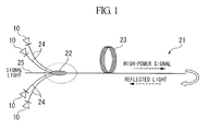
- FIG. 1 A structure of an optical amplifier using the multi-port coupler is illustrated in FIG. 1.
- An optical amplifier 21 of FIG. 1 is constructed to include a multi-port coupler 22 into which signal light and pumping light are incident and a cladding pump fiber 23 whose end is connected to an output terminal of the multi-port coupler 22.
- a signal fiber 25 constructed with a central SM fiber and pumping fibers 24 constructed with multi-mode fibers arranged around the signal fiber 25 are unified.
- a front side of the multi-port coupler 22 is reduced in diameter. The signal light and the pumping light can be incident into the cladding pump fiber 23 for optical amplification connected to a reduced-diameter output terminal of the multi-port coupler 22.
- a signal light source is connected to the signal fiber 25 coupled to the multi-port coupler 22.
- the LDs 10 are connected to the plurality of pumping fibers 24, respectively.
- the optical amplifier 21 excites rare earth ions doped into the core of the multi-port coupler 22 by propagating the pumping light (for example, a wavelength of 910 - 980 nm) to the cladding of the cladding pump fiber 23 through the multi-port coupler 22.
- the optical amplifier 21 amplifies incident signal light by propagating the signal light to the core of the cladding pump fiber 23 through the multi-port coupler 22, such that the amplified signal light (or high power signal) is output from the cladding pump fiber 23.
- the gain level is 20 dB or more and the maximum power is 1 W - 1 kW.
- the lifetime of LDs 10 should be prolonged to improve reliability in a conventionally used optical amplifier in which a multi-port coupler and a cladding pump fiber are combined.
- the applicants have conducted research on a structure for preventing the pump LD from being damaged even when the reflected light returns to the optical amplifier.
- an optical isolator is conventionally used in conventional technologies for suppressing the reflected light itself.
- the optical isolator may attenuate the reflectance to only about -20 dB and also the optical isolator for light of several watts (W) or more is too expensive.
- the reflected light propagates inside the core of the amplification fiber, the reflected light is not emitted to the pump LD as long as the light is not leaked from the core. According to the examination on how the reflected light is incident into the LD, it has been found that the reflected light is emitted to the pump LD due to the main cause of splice loss of the core caused at the splicing point of the multi-port coupler and the cladding pump fiber.
- the loss in the splicing point occurs since core diameters (or intensity distribution sizes) of two fibers are very different from each other.
- the high power cladding pump fiber has the core diameter of 20 ⁇ m or more.
- the core diameter of an SM fiber used for signal propagation is about 5 ⁇ m. For this reason, the magnitude of the loss in the splicing point becomes 5 dB or more, particularly in a propagation direction of the reflected light.
- the core diameter of the cladding pump fiber is large is that the optical power density is very large in a high power amplifier and the optical fiber is affected by the non-linear optical effect. To avoid this influence, the core diameter of the cladding pump fiber is increased and consequently the low optical energy density in the fiber is designed. However, since multi-mode transmission is difficult and also bend loss is large in the core whose sectional area is large, the core is not proper for the signal fiber. Accordingly, it is desirable that the transmission fiber has a core whose sectional area is small and the amplification fiber has a core whose sectional area is large.
- the multi-port coupler Since the multi-port coupler is arranged between these two fibers, splice loss may be reduced to a certain degree if the sectional area of the core of the multi-port coupler has a middle size between the sizes of the sectional areas of the two fibers. It is obvious that the structure of the multi-port coupler increases the splice loss without decreasing the splice loss, since an outer diameter of a fiber in the multi-pump coupler is reduced to conventionally couple multiple fibers to one fiber.
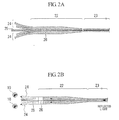
- FIGS. 2A and 2B illustrate a splicing point of the conventional multi-port coupler 22 and the cladding pump fiber 23 shown in FIG. 1.
- a front end of the multi-port coupler 22 connected to the cladding pump fiber 23 unifies a central signal fiber 25 having a core 26 and a plurality of pumping fibers 24 around the signal fiber 25, and has a structure in which the multi-port coupler 22 is reduced in diameter in a tapered shape toward an end so that an outer diameter of the multi-port coupler 22 can be the same as that of the cladding pump fiber 23.
- the diameter of the core of the central signal fiber 25 is further reduced.
- the cladding pump coupler 23 whose core has a large diameter is connected, a difference between the core diameters of fibers at both sides is further increased.
- an object of the present invention is to provide a multi-port coupler that can prevent an pumping light source from being damaged by reflected light in an optical amplifier or fiber laser using a multi-port coupler and that can prolong the lifetime of devices, and an optical amplifier and a fiber laser using the same.
- the present invention provides a multi-port coupler for coupling an pumping light source to a cladding pump fiber for optical amplification, comprising: a central signal fiber and a plurality of pumping fibers arranged around the central signal fiber, the central signal fiber and the plurality of pumping fibers being unified and a front side is reduced in diameter, wherein an emitted light confining waveguide part is provided around a core of the signal fiber located at the center, and the emitted light confining waveguide part whose outer diameter is larger than that of the core has a higher refractive index than a cladding and a lower refractive index than the core and the emitted light confining waveguide part is formed continuously from a splicing point of the cladding pump fiber to a coupler front end branched into multiple fibers.
- the emitted light confining waveguide part may be provided in a concentric circle shape around the core of the signal fiber.
- the emitted light confining waveguide part may be provided with a section of a polygonal shape around the core of the signal fiber.
- the present invention provides a multi-port coupler for coupling an pumping light source to a cladding pump fiber for optical amplification, comprising: a central signal fiber and a plurality of pumping fibers arranged around the central signal fiber, the central signal fiber and the plurality of pumping fibers being unified using a capillary, the capillary being connected to a rear end of a bridge fiber along with the signal fiber and the pumping fibers, a front side of the bridge fiber being reduced in diameter, wherein an emitted light confining waveguide part is provided around a core of the bridge fiber, the emitted light confining waveguide part whose outer diameter is larger than that of the core has a higher refractive index than a cladding and a lower refractive index than the core, and the capillary whose refractive index is lower than that of a cladding of the signal fiber, the capillary having an effect of confining emitted light in the signal fiber.
- the present invention provides a multi-port coupler for coupling an pumping light source to a cladding pump fiber for optical amplification, comprising: a central signal fiber and a plurality of pumping fibers arranged around the central signal fiber, the central signal fiber and the plurality of pumping fibers being unified using a capillary, the capillary being connected to a rear end of a bridge fiber along with the signal fiber and the pumping fibers, a front side of the bridge fiber being reduced in diameter, wherein an emitted light confining waveguide part is provided around a core of the bridge fiber, wherein the emitted light confining waveguide part whose outer diameter is larger than that of the core has a higher refractive index than a cladding and a lower refractive index than the core, the capillary whose refractive index is equal to that of a cladding of the signal fiber, and an pumping fiber cladding whose refractive index is lower than that of the capillary, the pumping fiber cla
- the emitted light confining waveguide part may be provided in a concentric circle shape around the core of the bridge fiber.
- the emitted light confining waveguide part may be provided with a section of a polygonal shape around the core of the bridge fiber.
- the outer diameter of the emitted light confining waveguide part may be smaller than that of the signal fiber connected to the multi-port coupler.
- the shape of confining waveguide is not an essential factor. However, a simpler shape is preferable in terms of productivity.
- an emitted light attenuation part may be provided in which the signal fiber is extended for an appropriate distance and rolled.
- the present invention provides an optical amplifier, including: the multi-port coupler of the present invention as described above; a cladding pump fiber for optical amplification; and an pumping light source.
- the present invention provides a fiber laser, including: the multi-port coupler of the present invention as described above; a cladding pump fiber for optical amplification; and an pumping light source.
- the multi-port coupler of the present invention is of a structure in which an emitted light confining waveguide part provided around a core of a signal fiber located at the center has an outer diameter which is larger than that of the core, a higher refractive index than a cladding and a lower refractive index than the core, reflected light returning to a laser diode (LD) is confined in the emitted light confining waveguide part, such that an pumping light source can be prevented from being damaged by the reflected light and the lifetime of devices can be prolonged.
- LD laser diode
- the optical amplifier of the present invention is of a structure in which pumping light and signal light are coupled to a cladding pump fiber for optical amplification using the multi-port coupler of the present invention as described above, reflected light returning to an LD is confined in an emitted light confining waveguide part of the optical amplifier, such that an pumping light source can be prevented from being damaged by the reflected light and the lifetime of devices can be prolonged.
- the fiber laser of the present invention is of a structure in which pumping light and signal light are coupled to a cladding pump fiber for optical amplification using the multi-port coupler of the present invention as described above, reflected light returning to an LD is confined in an emitted light confining waveguide part of the fiber laser, such that an pumping light source can be prevented from being damaged by the reflected light and the lifetime of devices can be prolonged.
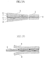
- FIG. 3 is cross-sectional views illustrating an embodiment of a multi-port coupler in accordance with the present invention.
- FIG. 3A is a cross-sectional view illustrating a structure of a front side of a multi-port coupler 2
- FIG. 3B is a cross-sectional view illustrating a structure of the other end side of the multi-port coupler 2.
- a central signal fiber 5 and a plurality of pumping fibers 4 arranged around the central signal fiber 5 are unified.
- the front side of the multi-port coupler 2 is reduced in diameter.
- an emitted light confining waveguide part 7 is provided in a concentric circle shape around a core 6 of the signal fiber 5 located at the center and has an outer diameter which is larger than that of the core 6.
- the emitted light confining waveguide part 7 has a higher refractive index than a cladding 8 and a lower refractive index than the core 6.
- the emitted light confining waveguide part 7 is formed continuously from a splicing point for the cladding pump fiber 3 to a coupler front end branched into multiple fibers 4 and 5.
- the applicants have analyzed a mechanism in which a laser diode (LD) is damaged and have invented a structure in which no LD is damaged even when splice loss occurs in a multi-port coupler.
- the applicants have focused on an internal structure of the multi-port coupler.
- the signal fiber 5 serving as the center and the plurality of pumping fibers 4 arranged around the signal fiber 5 are unified. It has been found that emitted light can be effectively confined in an area whose refractive index is high and therefore the emitted light can be prevented from entering an excitation port even when the splice loss occurs and externally emitted light is generated, if the emitted light confining waveguide part 7 formed around the core 6 of the signal fiber 5 as illustrated in FIG. 3 has a slightly higher refractive index than its periphery.
- the constant value A can vary with the core diameter of the cladding pump fiber 3 for optical amplification and the relative refractive index difference relative to the cladding, since the angle or intensity of emitted light is determined by the core 9 of the cladding pump fiber 3.
- the emitted light confining waveguide part 7 should be provided from the splicing point of the cladding pump fiber 3 to an area in which the pumping fiber 4 is separated from the signal fiber 5, since the emitted light may be coupled to the pumping fiber 4 when the emitted light is unable to be confined on the way.
- the diameter of the emitted light confining waveguide part 7 is smaller than the outer diameter of the cladding of the signal fiber 5, since the emitted light confined within the waveguide is coupled to the pumping fiber 4 at a coupler front end if the diameter of the emitted light confining waveguide part 7 is larger than the outer diameter of the cladding of the signal fiber 5.
- the emitted light confined in the emitted light confining waveguide part 7 is propagated through the signal fiber 5 in reverse as illustrated in FIG. 3B, the emitted light is gradually absorbed and vanished by a resin outside a glass cladding.
- the signal fiber has the ⁇ diameter of 50 mm and the length of about 1 m.
- the emitted light can be absorbed by addition of a dopant for enabling the emitted light to be absorbed by a cladding part.
- a dopant for enabling the emitted light to be absorbed by a cladding part.
- an Sm doped fiber is effective to absorb the light with a wavelength of 1064 nm.
- the relative refractive index difference between the core and the emitted light confining waveguide part is 0.4%
- the relative refractive index difference between the emitted light confining waveguide part and the cladding is 0.05%
- the diameter of the emitted light confining waveguide part is 60 ⁇ m.
- the pump LD Since the pump LD is damaged by power at least twice as high as the output power of the pump LD itself in the case where the pump LD is conventionally damaged, the effect of reduction to 8% is very large. Conventionally, the excitation power is about 5 - 10 W.
- A 1.5 [ ⁇ m *%]
- 85% of the emitted light can be confined in the same case.
- the reflected light is reduced to 15% of 20 W, that is, 3 W, and also the pump LD can be effectively protected.
- the multi-port coupler 2 of this embodiment can efficiently gather pumping light in a core 9 of the cladding pump fiber 3 by providing the emitted light confining waveguide part 7 around the signal fiber 5.
- the pumping light uniformly distributed to the cladding is efficiently absorbed by the core 9. If the pumping light can be gathered in the core 9, the pumping light can be efficiently absorbed (since the absorption happens only in the core).
- the core 9 of the cladding pump fiber 3 increases the absorption efficiency of the pumping light by 20%.
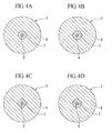
- the core 6 of the signal fiber and the emitted light confining waveguide part 7 provided around the core 6 have a section of a concentric circle shape as illustrated in FIG. 4A.
- the present invention is not limited to the emitted light confining waveguide part 7 of FIG. 4A.
- the emitted light confining waveguide part 7 can have a section of a polygonal shape such as a hexagonal shape as illustrated in FIG. 4B, a square shape as illustrated in FIG. 4C, or a pentagonal shape as illustrated in FIG. 4D.
- the sectional shape of the emitted light confining waveguide part 7 is the polygonal shape, reflected light can be confined in the signal fiber 5 and power incident into the pumping fiber 4 can be reduced as in the concentric circle shape.
- the outer diameter of the emitted light confining waveguide part 7 is smaller than the outer diameter (or cladding diameter) of the signal fiber 5 connected to the multi-port coupler 2 when the section of the emitted light confining waveguide part 7 has the polygonal shape, it means that the diameter of an inscribed circle of the emitted light confining waveguide part 7 is smaller than the outer diameter of the signal fiber 5.
- the emitted light confining waveguide part 7 is included within a cladding area of the signal fiber 5 in a total sectional area, a whole of emitted light confined within the emitted light confining waveguide part 7 is supplied to the signal fiber 5 and a coupler front end controls the emitted light to be supplied to the pumping fiber 4, so that the same desired effect can be achieved.
- the pump LD can be effectively prevented from being damaged by reflected light and also pumping light can be efficiently distributed around a core, by providing an area in which light is confined around the core in a waveguide structure inside the multi-port coupler as described above.
- the pumping light can be efficiently gathered around the core by adopting the above described structure.
- the multi-port coupler of the present invention can have a structure in which a signal fiber and pumping fibers are convergent in a capillary structure and a front end of the capillary structure is connected to a bridge fiber having a reduced-diameter front end and an emitted light confining waveguide part.
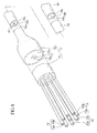
- a central signal fiber 12 and a plurality of pumping fibers 13 arranged around the central signal fiber 12 are unified using a capillary 14.
- the capillary 14 is connected to a rear end of a bridge fiber 15.
- a front side of the bridge fiber 15 is reduced in diameter (or not being changed in diameter).
- an emitted light confining waveguide part 17 is provided around a core 15a of the bridge fiber 15.
- the emitted light confining waveguide part 17 whose outer diameter is larger than that of the core 15a has a higher refractive index than a cladding 15b and a lower refractive index than the core 15a.
- the capillary 14 is a porous capillary having multiple through holes (or fine pores) into which the signal fiber 12 and the pumping fibers 13 are inserted.
- the porous capillary is made of silica-based glass to which the quartz glass or dopant is added for fusion splicing fibers.
- the fusion splice can be made using a thermal source such as arc discharging, carbon dioxide gas laser, oxyhydrogen flame, or the like.
- a core 12a of the signal fiber 12 inserted into a central fine pore of the capillary 14 is coupled to the core 15a of the bridge fiber 15.
- Cores 13a of the pumping fibers 13 inserted into fine pores around the central fine pore are coupled to the cladding 15b of the bridge fiber 15.
- a reduced-diameter part of the front side of the bridge fiber 15 can be formed, for example, through heating drawing in a tapered shape.
- the following structures (1) and (2) are used to prevent reflected light from being incident into the pumping fibers 13.
- the emitted light can be coupled to the capillary 14, but the emitted light can be prevented from being coupled to the pumping fiber 13 since the cladding 13b of the pumping fiber 13 has the effect of confining the reflected light in the capillary 14.
- the diameter (or outer diameter) of the emitted light confining waveguide part 17 provided in the bridge fiber 15 is smaller than the outer diameter (or cladding diameter) of the signal fiber 12, since the emitted light confined in the waveguide is coupled to the pumping fiber 13 at the coupler front end if the diameter of the emitted light confining waveguide part 17 is larger than the outer diameter of the signal fiber.
- the emitted light confined in the emitted light waveguide part 17 is propagated through the signal fiber 12 in reverse (or in a direction from the right to the left in FIG. 5), the emitted light is gradually absorbed and vanished by a resin outside of the cladding 12b of the signal fiber 12.
- the signal fiber 12 has the ⁇ diameter of 50 mm and the length of about 1 m.
- the emitted light can be absorbed by addition of a dopant for enabling the emitted light to be absorbed by a part of the cladding 12b of the signal fiber 12.
- a dopant for enabling the emitted light to be absorbed by a part of the cladding 12b of the signal fiber 12.
- an Sm doped fiber is effective to absorb the light with the wavelength of 1064 nm.
- all the cladding 12b of the signal fiber 12, the capillary 14, and the cores 13a of the pumping fibers 13 are made of quartz (whose refractive index is about 1.448).
- the cladding 13b of the pumping fiber 13 has the thickness of 10 ⁇ m in the refractive index of 1.436 (when the relative refractive index difference between the core 13a and the capillary 14 is 0.8%).
- the intensity of the reflected light coupled to the pumping fibers 13 can be reduced to about 20 dB (that is, about 1/100), in the structure (2) compared with a structure where a low refractive index part based on the claddings 13b of the pumping fibers 13 is not provided.
- the refractive index of the capillary 14 is lower than that of the cladding 12b of the signal fiber 12
- all the cladding 12b of the signal fiber 12 and the cores 13a of the pumping fibers 13 are made of quartz (whose refractive index is about 1.448).
- the cladding 13b of the pumping fiber 13 has the thickness of 10 ⁇ m in the refractive index of 1.436 (when the relative refractive index difference between the core 13a and the capillary 14 is 0.8%) and also the capillary 14 has the refractive index of 1.436.
- the intensity of the reflected light coupled to the pumping fibers 13 can be further reduced by 8 dB in the structure (1) compared with the structure (2).
- the reduction of about 28 dB can be achieved.
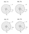
- the core 15a of the bridge fiber 15 and the emitted light confining waveguide part 17 provided around the core 15a have a section of a concentric circle shape as illustrated in FIG. 7A, respectively.
- the present invention is not limited to the emitted light confining waveguide part 17 of FIG. 7A.
- the emitted light confining waveguide part 17 can have a section of a polygonal shape such as a hexagonal shape as illustrated in FIG. 7B, a square shape as illustrated in FIG. 7C, or a pentagonal shape as illustrated in FIG. 7D.
- the sectional shape of the emitted light confining waveguide part 17 is the polygonal shape
- reflected light is confined in the core 15a of the bridge fiber 1 5 and is coupled to the signal fiber 12 and power incident into the pumping fibers 13 can be reduced as in the concentric circle shape.
- the outer diameter of the emitted light confining waveguide part 17 is smaller than the outer diameter (or cladding diameter) of the signal fiber 12 connected to the multi-port coupler 11 when the section of the emitted light confining waveguide part 17 has the polygonal shape, it means that the diameter of an inscribed circle of the emitted light confining waveguide part 17 is smaller than the outer diameter of the signal fiber 12.
- the emitted light confining waveguide part 17 is included within a cladding area of the signal fiber 12 in a total sectional area, a whole of emitted light confined within the emitted light confining waveguide part 17 is supplied to the signal fiber 12 and a coupler front end controls the emitted light to be supplied to the pumping fiber 13, such that the same desired effect can be achieved.
- the emitted light confining waveguide part 17 is provided around the core 15a of the bridge fiber 15 also in the multi-port coupler 11 of this embodiment, pumping light from the pumping fiber 13 can be efficiently gathered in a core 16a of a cladding pump fiber 16.
- the pumping light uniformly distributed to the cladding is efficiently absorbed by the core 16a. If the pumping light can be gathered in the core 16a, the pumping light can be efficiently absorbed (since the absorption happens only in the core).
- the cladding pump fiber 16 connected to the multi-port coupler 11 uses a double cladding fiber (DCF) in which a rare earth element is added to the core 16a and an inner cladding 16b and an outer cladding 16c are provided around the core 16a.
- DCF double cladding fiber
- the multi-port coupler I 1 of this embodiment is connected to a cladding pump fiber (or non-dope DCF) 18 in which no rare earth element is added to a core 18a as illustrated in FIG. 8.
- the rare earth element doped DCF 16 is connected to an end of one side of the non-dope DCF 18 and a reduced-diameter front end of the bridge fiber 15 is connected to an end of the other side of the non-dope DCF 18.
- an emitted light confining waveguide part 19 should be provided between the core 18a and claddings 18b and 18c to confine emitted light in the core 18a without emitting the light from a splicing point of the non-dope DCF 18 and the rare earth element doped DCF 16 to the claddings 18b and 18c of the non-dope DCF 18.
- the emitted light confining waveguide part 19 has a higher refractive index than the claddings 18b and 18c and a lower refractive index than the core 18a.
- a sectional shape of the emitted light confining waveguide part 19 can be a concentric circle shape and a polygonal shape relative to the core 18a.
- the multi-port coupler In this structure compared with the structure in which the multi-port coupler is directly connected to a rare earth element doped DCF, the multi-port coupler, the multi-port coupler can suppress the incidence of the reflected light to the pumping fiber 13 at the exactly same level.
- the pump LD can be effectively prevented from being damaged by reflected light and also pumping light can be efficiently distributed around a core, by providing an area in which light is confined around the core in a waveguide structure inside the multi-port coupler as described above.
- the pumping light can be efficiently gathered around the core by adopting the above described structure.
- the effect of suppressing the destruction of an LD was examined by applying the multi-port coupler of the present invention (as illustrated in FIG. 3) to an optical amplifier of an excitation wavelength of 915 nm and a signal wavelength of 1064 nm.
- An Yb doped double cladding fiber was used as a cladding pump fiber.
- the core diameter is 20 ⁇ m
- the relative refractive index difference ⁇ between the core and the inner cladding is 0.1%
- the outer diameter of the inner cladding is 400 ⁇ m.
- the core diameter is 105 ⁇ m and the relative refractive index difference ⁇ between the core and the cladding is 0.55%.
- a reflection point was located before the optical amplifier and about 5% of light output from the optical amplifier was set to return to the optical amplifier.
- experimentation was performed with a multi-port coupler manufactured in the core diameter of 2.5 ⁇ m, the diameter of the emitted light confining waveguide part of 30 ⁇ m, and the relative refractive index difference of the emitted light confining waveguide part of 0.1 % in accordance with the present invention and two couplers without the emitted light confining waveguide part.
- the emitted light confining waveguide part 17 of 45 ⁇ m was formed on a side around the core 15a.
- the relative refractive index difference between the emitted light confining waveguide part 17 and the cladding 15b was 0.1% and the relative refractive index difference between the core 15a and the emitted light confining waveguide part 17 was 0.18%.
- the outer diameter of the emitted light confining waveguide part 17 When the outer diameter of the emitted light confining waveguide part 17 is approximated to the diameter of a circle between the inscribed circle of the hexagon shape and the circumscribed circle, the outer diameter of the emitted light confining waveguide part 17 becomes 42 ⁇ m.
- the cladding pump fiber 16 having the core diameter of 30 ⁇ m and the relative refractive index difference of 0.12% between the core and the cladding was prepared. Upon determining how much emitted light was confined in a splicing point between the bridge fiber 15 and the cladding pump fiber 16,95% or more of the emitted light could be confined in the core 15a of the bridge fiber 15.
Landscapes
- Physics & Mathematics (AREA)
- General Physics & Mathematics (AREA)
- Optics & Photonics (AREA)
- Lasers (AREA)
- Optical Couplings Of Light Guides (AREA)
Applications Claiming Priority (2)
| Application Number | Priority Date | Filing Date | Title |
|---|---|---|---|
| JP2006149696 | 2006-05-30 | ||
| JP2006260881A JP5089950B2 (ja) | 2006-05-30 | 2006-09-26 | マルチポートカプラ、光増幅器及びファイバレーザ |
Publications (3)
| Publication Number | Publication Date |
|---|---|
| EP1862830A2 true EP1862830A2 (de) | 2007-12-05 |
| EP1862830A3 EP1862830A3 (de) | 2008-06-25 |
| EP1862830B1 EP1862830B1 (de) | 2017-02-08 |
Family
ID=38336833
Family Applications (1)
| Application Number | Title | Priority Date | Filing Date |
|---|---|---|---|
| EP07252215.4A Ceased EP1862830B1 (de) | 2006-05-30 | 2007-05-30 | Multiportkoppler, optischer Verstärker und Faserlaser |
Country Status (3)
| Country | Link |
|---|---|
| US (1) | US7492993B2 (de) |
| EP (1) | EP1862830B1 (de) |
| JP (1) | JP5089950B2 (de) |
Cited By (3)
| Publication number | Priority date | Publication date | Assignee | Title |
|---|---|---|---|---|
| EP2071376A1 (de) * | 2007-12-14 | 2009-06-17 | Corelase OY | Faseroptischer Kobinierer mit einer Vorform, die kappilare Öffnungen besitzt und zugehöriges Herstellungsverfahren |
| DE102008020828A1 (de) * | 2008-04-25 | 2009-10-29 | Jt Optical Engine Gmbh + Co. Kg | Faserkoppler |
| US9417391B2 (en) | 2013-08-22 | 2016-08-16 | Fujikura Ltd. | Optical combiner and laser device using the same |
Families Citing this family (58)
| Publication number | Priority date | Publication date | Assignee | Title |
|---|---|---|---|---|
| JP4899705B2 (ja) * | 2006-08-08 | 2012-03-21 | 住友電気工業株式会社 | 光増幅モジュール |
| JP2008226886A (ja) * | 2007-03-08 | 2008-09-25 | Fujikura Ltd | 光ポンピングデバイス、光増幅器、ファイバレーザ及び光ポンピングデバイス用マルチコアファイバとその製造方法 |
| WO2009077636A1 (en) * | 2007-12-14 | 2009-06-25 | Corelase Oy | Means of coupling light into optical fibers and methods of manufacturing a coupler |
| WO2009082733A1 (en) * | 2007-12-21 | 2009-07-02 | Stockeryale, Inc. | High power pulsed fiber laser |
| JP2009212441A (ja) * | 2008-03-06 | 2009-09-17 | Fujikura Ltd | ポンプコンバイナ |
| US9063289B1 (en) * | 2008-06-30 | 2015-06-23 | Nlight Photonics Corporation | Multimode fiber combiners |
| US20130216184A1 (en) | 2008-07-14 | 2013-08-22 | Victor Il'ich Kopp | Configurable pitch reducing optical fiber array |
| FR2935554B1 (fr) * | 2008-09-02 | 2012-04-13 | Centre Nat Rech Scient | Dispositif laser a fibre de forte puissance moyenne |
| US9494738B1 (en) | 2009-05-28 | 2016-11-15 | Nlight, Inc. | Single mode fiber combiners |
| US8818151B1 (en) * | 2009-08-03 | 2014-08-26 | United States Of America As Represented By The Secretary Of The Air Force | Fiber Pump Signal Combiner |
| US8184363B2 (en) * | 2009-08-07 | 2012-05-22 | Northrop Grumman Systems Corporation | All-fiber integrated high power coherent beam combination |
| EP2477284B1 (de) * | 2009-10-27 | 2019-09-18 | Fujikura Ltd. | Lichtkombinator und faserlaserelement damit |
| JP5782104B2 (ja) * | 2010-03-16 | 2015-09-24 | オーエフエス ファイテル,エルエルシー | マルチコアファイバへの低損失でモードフィールドが整合された結合のための方法、および装置 |
| EP2548056B1 (de) * | 2010-03-16 | 2021-05-05 | OFS Fitel, LLC | Mehrkernübertragungs- und -verstärkerfasern sowie schemen zum einbringen von pumplicht in verstärkerkerne |
| JP2011203544A (ja) * | 2010-03-26 | 2011-10-13 | Fujikura Ltd | 光ファイバの接続方法、及び、光ファイバの接続構造 |
| JP5512348B2 (ja) | 2010-03-29 | 2014-06-04 | 株式会社フジクラ | 光学部品付き増幅用光ファイバ、及び、これを用いたファイバレーザ装置 |
| JP2012059746A (ja) * | 2010-09-06 | 2012-03-22 | Fujikura Ltd | ファイバレーザ及びレーザ加工機 |
| FI125306B (fi) * | 2010-10-21 | 2015-08-31 | Rofin Sinar Laser Gmbh | Paketoitu kuituoptinen komponentti ja menetelmä sen valmistamiseksi |
| JP5643632B2 (ja) * | 2010-12-16 | 2014-12-17 | 株式会社フジクラ | マルチポートカプラ、及び、それを用いた光ファイバ増幅器及びファイバレーザ装置及び共振器 |
| US8903211B2 (en) * | 2011-03-16 | 2014-12-02 | Ofs Fitel, Llc | Pump-combining systems and techniques for multicore fiber transmissions |
| US9007681B2 (en) * | 2011-12-13 | 2015-04-14 | Ofs Fitel, Llc | Multi-core erbium-doped fiber amplifier |
| US9025239B2 (en) * | 2011-12-13 | 2015-05-05 | Ofs Fitel, Llc | Multi-core erbium-doped fiber amplifier |
| JP5469191B2 (ja) * | 2012-03-27 | 2014-04-09 | 株式会社フジクラ | 光学部品、及び、これを用いた光ファイバ増幅器及びレーザ装置 |
| JP5990419B2 (ja) * | 2012-07-09 | 2016-09-14 | 株式会社フジクラ | 光学入出力デバイス |
| JP5584280B2 (ja) | 2012-12-21 | 2014-09-03 | 株式会社フジクラ | ブリッジファイバ、コンバイナ及びファイバレーザ装置 |
| CN103676004B (zh) * | 2012-12-28 | 2016-08-17 | 清华大学 | 光纤分束装置 |
| WO2014105756A1 (en) | 2012-12-31 | 2014-07-03 | Nlight Photonics Corporation | Spatially stable high brightness fiber |
| CN103149638A (zh) * | 2013-03-22 | 2013-06-12 | 清华大学 | 光纤耦合器 |
| US10914891B2 (en) * | 2013-06-14 | 2021-02-09 | Chiral Photonics, Inc. | Multichannel optical coupler |
| US11966091B2 (en) * | 2013-06-14 | 2024-04-23 | Chiral Photonics, Inc. | Multichannel optical coupler array |
| US10564348B2 (en) * | 2013-06-14 | 2020-02-18 | Chiral Photonics, Inc. | Passive aligning optical coupler array |
| US11156781B2 (en) * | 2013-06-14 | 2021-10-26 | Chiral Photonics, Inc. | Passive aligning optical coupler array |
| US10838155B2 (en) | 2013-06-14 | 2020-11-17 | Chiral Photonics, Inc. | Multichannel optical coupler |
| US10101536B2 (en) | 2013-06-14 | 2018-10-16 | Chiral Photonics, Inc. | Multichannel optical coupler array |
| US10126494B2 (en) | 2013-06-14 | 2018-11-13 | Chiral Photonics, Inc. | Configurable polarization mode coupler |
| JP5814314B2 (ja) | 2013-08-09 | 2015-11-17 | 株式会社フジクラ | 光コンバイナ、及び、それを用いたレーザ装置、並びに、光コンバイナの製造方法 |
| US9537282B2 (en) * | 2013-09-20 | 2017-01-03 | Alcatel Lucent | System and method for a multi-mode pump in an optical amplifier |
| US10069271B2 (en) * | 2014-06-02 | 2018-09-04 | Nlight, Inc. | Scalable high power fiber laser |
| US9664850B2 (en) * | 2014-09-21 | 2017-05-30 | Alcatel-Lucent Usa Inc. | Optical spatial mode-multiplexer |
| JP5908559B1 (ja) * | 2014-10-17 | 2016-04-26 | 株式会社フジクラ | 光カプラ、レーザ装置、及びテーパファイバ |
| US9362709B1 (en) * | 2015-01-21 | 2016-06-07 | Ofs Fitel, Llc | Optical fiber laser architecture with partitioned pump and signal coupling |
| JP6140743B2 (ja) * | 2015-02-12 | 2017-05-31 | 株式会社フジクラ | ファイバレーザ装置および増幅用コイルの製造方法 |
| US9917411B2 (en) * | 2015-06-25 | 2018-03-13 | Optical Engines, Inc. | Double fiber optic mode adapter |
| CN108367389B (zh) | 2015-11-23 | 2020-07-28 | 恩耐公司 | 激光加工方法和装置 |
| US10730785B2 (en) | 2016-09-29 | 2020-08-04 | Nlight, Inc. | Optical fiber bending mechanisms |
| WO2018063452A1 (en) | 2016-09-29 | 2018-04-05 | Nlight, Inc. | Adjustable beam characteristics |
| EP3535612B1 (de) * | 2016-11-03 | 2023-06-14 | Chiral Photonics, Inc. | Mehrkanalige optische koppleranordnung |
| WO2018152338A1 (en) * | 2017-02-15 | 2018-08-23 | Nufern | Optical amplifying systems and methods |
| CN107017551A (zh) * | 2017-05-27 | 2017-08-04 | 中国工程物理研究院应用电子学研究所 | 一种(2+1)×1侧面融锥型光纤泵浦合束器的封装方法 |
| WO2018227008A1 (en) * | 2017-06-08 | 2018-12-13 | Chiral Photonics, Inc. | Optical coupler arrays |
| CN109390842B (zh) * | 2017-08-10 | 2020-06-02 | 大族激光科技产业集团股份有限公司 | 泵浦合束器空余输入支路回返光的处理方法及光纤激光器 |
| US12493147B2 (en) | 2018-04-23 | 2025-12-09 | Legrand DPC, LLC | Continuously formed optical fiber with different core profile zones |
| US12493149B2 (en) * | 2018-04-23 | 2025-12-09 | Legrand DPC, LLC | Cyclic core variance system |
| CN111025477A (zh) * | 2019-11-20 | 2020-04-17 | 桂林电子科技大学 | 一种单模光纤与毛细管光纤耦合器及其制备方法 |
| US12210185B2 (en) | 2020-02-24 | 2025-01-28 | Chiral Photonics, Inc. | Wavelength division multiplexers for space division multiplexing (SDM-WDM devices) |
| US11061188B1 (en) * | 2020-03-02 | 2021-07-13 | Ad Value Photonics, Inc. | Fiber coupler and method for fabrication of the same |
| CN111545145A (zh) * | 2020-04-10 | 2020-08-18 | 桂林电子科技大学 | 一种温度可控的纤维集成微量反应腔 |
| US12548966B2 (en) * | 2023-07-12 | 2026-02-10 | Lumentum Operations Llc | Multiple signal fiber, optical pump-signal combiner |
Citations (3)
| Publication number | Priority date | Publication date | Assignee | Title |
|---|---|---|---|---|
| US20050105854A1 (en) | 2003-11-13 | 2005-05-19 | Imra America, Inc. | Optical fiber pump multiplexer |
| WO2006007652A1 (en) | 2004-07-21 | 2006-01-26 | Australian Postal Corporation | Improvements in or relating to tickets |
| WO2007107163A1 (en) | 2006-03-17 | 2007-09-27 | Crystal Fibre A/S | An optical coupler, a method of its fabrication and use |
Family Cites Families (9)
| Publication number | Priority date | Publication date | Assignee | Title |
|---|---|---|---|---|
| AU697467B2 (en) * | 1994-12-28 | 1998-10-08 | Ire-Polus Co. | A coupling arrangement between a multi-mode light source and an optical fiber through an intermediate optical fiber length |
| US5867305A (en) * | 1996-01-19 | 1999-02-02 | Sdl, Inc. | Optical amplifier with high energy levels systems providing high peak powers |
| JP2962248B2 (ja) * | 1996-11-01 | 1999-10-12 | 日本電気株式会社 | 波長多重光伝送用光増幅装置 |
| US5898715A (en) * | 1997-06-09 | 1999-04-27 | Lucent Technologies Inc. | Optical communication system comprising a cladding pumped fiber laser |
| US5864644A (en) * | 1997-07-21 | 1999-01-26 | Lucent Technologies Inc. | Tapered fiber bundles for coupling light into and out of cladding-pumped fiber devices |
| US6434302B1 (en) * | 1998-03-04 | 2002-08-13 | Jds Uniphase Corporation | Optical couplers for multimode fibers |
| FR2834347B1 (fr) * | 2002-01-03 | 2004-04-09 | Cit Alcatel | Coupleur optique pour pompe multimode |
| WO2006076524A2 (en) * | 2005-01-14 | 2006-07-20 | Comcore Technologies Inc. | Tapered fiber bundles and devices |
| JP4762833B2 (ja) * | 2006-09-05 | 2011-08-31 | 浜松ホトニクス株式会社 | 光学部品 |
-
2006
- 2006-09-26 JP JP2006260881A patent/JP5089950B2/ja not_active Expired - Fee Related
-
2007
- 2007-05-30 EP EP07252215.4A patent/EP1862830B1/de not_active Ceased
- 2007-05-30 US US11/755,681 patent/US7492993B2/en active Active
Patent Citations (3)
| Publication number | Priority date | Publication date | Assignee | Title |
|---|---|---|---|---|
| US20050105854A1 (en) | 2003-11-13 | 2005-05-19 | Imra America, Inc. | Optical fiber pump multiplexer |
| WO2006007652A1 (en) | 2004-07-21 | 2006-01-26 | Australian Postal Corporation | Improvements in or relating to tickets |
| WO2007107163A1 (en) | 2006-03-17 | 2007-09-27 | Crystal Fibre A/S | An optical coupler, a method of its fabrication and use |
Cited By (5)
| Publication number | Priority date | Publication date | Assignee | Title |
|---|---|---|---|---|
| EP2071376A1 (de) * | 2007-12-14 | 2009-06-17 | Corelase OY | Faseroptischer Kobinierer mit einer Vorform, die kappilare Öffnungen besitzt und zugehöriges Herstellungsverfahren |
| DE102008020828A1 (de) * | 2008-04-25 | 2009-10-29 | Jt Optical Engine Gmbh + Co. Kg | Faserkoppler |
| WO2009129774A3 (de) * | 2008-04-25 | 2009-12-17 | Jt Optical Engine Gmbh + Co. Kg | Faserkoppler |
| US8787716B2 (en) | 2008-04-25 | 2014-07-22 | Trumpf Laser Gmbh + Co. Kg | Fibre coupler |
| US9417391B2 (en) | 2013-08-22 | 2016-08-16 | Fujikura Ltd. | Optical combiner and laser device using the same |
Also Published As
| Publication number | Publication date |
|---|---|
| JP2008010804A (ja) | 2008-01-17 |
| EP1862830A3 (de) | 2008-06-25 |
| JP5089950B2 (ja) | 2012-12-05 |
| US20070280597A1 (en) | 2007-12-06 |
| US7492993B2 (en) | 2009-02-17 |
| EP1862830B1 (de) | 2017-02-08 |
Similar Documents
| Publication | Publication Date | Title |
|---|---|---|
| EP1862830B1 (de) | Multiportkoppler, optischer Verstärker und Faserlaser | |
| US11073656B2 (en) | Optical coupler and optical amplifier | |
| US9634462B2 (en) | Slanted FBG for SRS suppression | |
| US7593435B2 (en) | Powerful fiber laser system | |
| US7437046B2 (en) | Optical fiber configuration for dissipating stray light | |
| US8094370B2 (en) | Cladding pumped fibre laser with a high degree of pump isolation | |
| EP1933183B1 (de) | Hybrider Multimode-Lichtwellenleiter mit großer Modenfläche | |
| JP6683775B2 (ja) | 非一様に構成されたファイバ−ファイバロッドマルチモード増幅器を備える超ハイパワー単一モードファイバレーザシステム | |
| EP1935068B1 (de) | Optischer faserlaser | |
| CN100520466C (zh) | 多端口耦合器、光放大器及光纤激光器 | |
| JP2009212441A (ja) | ポンプコンバイナ | |
| JP5688565B2 (ja) | ファイバレーザ装置と光増幅方法 | |
| KR20140102706A (ko) | 분산 모드 흡수기를 구비한 고전력 광섬유 레이저 시스템 | |
| CN109690885B (zh) | 具有诱导杂散光损耗机制的光纤激光器系统 | |
| EP1429434B1 (de) | Optisches System zur Einkopplung des von einem Diodenarray ausgehenden Lichts in eine optische Faser | |
| US8902494B2 (en) | Amplification optical fiber with optical component and fiber laser device including the same | |
| US20080144673A1 (en) | Fiber laser with large mode area fiber | |
| JP4959314B2 (ja) | 希土類ドープ大モードエリア・マルチモード光ファイバおよびそれを使ったデバイス | |
| CN111817120B (zh) | 一种抑制受激拉曼散射效应的光纤及其应用 | |
| JP5014640B2 (ja) | マルチモードファイバ、光増幅器及びファイバレーザ | |
| JP2020167294A (ja) | ファイバレーザ装置 | |
| JP2007294534A (ja) | 光学的モジュール | |
| US20230042363A1 (en) | Optical fiber connector and fiber laser device | |
| JP2007324452A (ja) | 光結合器、ファイバレーザ及び光ファイバ増幅器 |
Legal Events
| Date | Code | Title | Description |
|---|---|---|---|
| PUAI | Public reference made under article 153(3) epc to a published international application that has entered the european phase |
Free format text: ORIGINAL CODE: 0009012 |
|
| 17P | Request for examination filed |
Effective date: 20070619 |
|
| AK | Designated contracting states |
Kind code of ref document: A2 Designated state(s): AT BE BG CH CY CZ DE DK EE ES FI FR GB GR HU IE IS IT LI LT LU LV MC MT NL PL PT RO SE SI SK TR |
|
| AX | Request for extension of the european patent |
Extension state: AL BA HR MK YU |
|
| PUAL | Search report despatched |
Free format text: ORIGINAL CODE: 0009013 |
|
| AK | Designated contracting states |
Kind code of ref document: A3 Designated state(s): AT BE BG CH CY CZ DE DK EE ES FI FR GB GR HU IE IS IT LI LT LU LV MC MT NL PL PT RO SE SI SK TR |
|
| AX | Request for extension of the european patent |
Extension state: AL BA HR MK RS |
|
| RIC1 | Information provided on ipc code assigned before grant |
Ipc: G02B 6/00 20060101AFI20070820BHEP Ipc: H01S 3/067 20060101ALI20080519BHEP Ipc: H01S 3/094 20060101ALI20080519BHEP |
|
| 17Q | First examination report despatched |
Effective date: 20090128 |
|
| AKX | Designation fees paid |
Designated state(s): DE FR GB IT |
|
| REG | Reference to a national code |
Ref country code: DE Ref legal event code: R079 Ref document number: 602007049755 Country of ref document: DE Free format text: PREVIOUS MAIN CLASS: G02B0006000000 Ipc: G02B0006280000 |
|
| RIC1 | Information provided on ipc code assigned before grant |
Ipc: H01S 3/0941 20060101ALI20160316BHEP Ipc: H01S 3/067 20060101ALI20160316BHEP Ipc: H01S 3/094 20060101ALI20160316BHEP Ipc: G02B 6/28 20060101AFI20160316BHEP |
|
| GRAP | Despatch of communication of intention to grant a patent |
Free format text: ORIGINAL CODE: EPIDOSNIGR1 |
|
| INTG | Intention to grant announced |
Effective date: 20160502 |
|
| GRAS | Grant fee paid |
Free format text: ORIGINAL CODE: EPIDOSNIGR3 |
|
| GRAJ | Information related to disapproval of communication of intention to grant by the applicant or resumption of examination proceedings by the epo deleted |
Free format text: ORIGINAL CODE: EPIDOSDIGR1 |
|
| GRAL | Information related to payment of fee for publishing/printing deleted |
Free format text: ORIGINAL CODE: EPIDOSDIGR3 |
|
| RAP1 | Party data changed (applicant data changed or rights of an application transferred) |
Owner name: FUJIKURA LTD. |
|
| RIN1 | Information on inventor provided before grant (corrected) |
Inventor name: SAKAI, TETSUYA Inventor name: NAKAI, MICHIHIRO |
|
| GRAP | Despatch of communication of intention to grant a patent |
Free format text: ORIGINAL CODE: EPIDOSNIGR1 |
|
| INTC | Intention to grant announced (deleted) | ||
| RIN1 | Information on inventor provided before grant (corrected) |
Inventor name: NAKAI, MICHIHIRO Inventor name: SAKAI, TETSUYA |
|
| GRAJ | Information related to disapproval of communication of intention to grant by the applicant or resumption of examination proceedings by the epo deleted |
Free format text: ORIGINAL CODE: EPIDOSDIGR1 |
|
| GRAP | Despatch of communication of intention to grant a patent |
Free format text: ORIGINAL CODE: EPIDOSNIGR1 |
|
| GRAJ | Information related to disapproval of communication of intention to grant by the applicant or resumption of examination proceedings by the epo deleted |
Free format text: ORIGINAL CODE: EPIDOSDIGR1 |
|
| GRAP | Despatch of communication of intention to grant a patent |
Free format text: ORIGINAL CODE: EPIDOSNIGR1 |
|
| INTG | Intention to grant announced |
Effective date: 20161122 |
|
| GRAR | Information related to intention to grant a patent recorded |
Free format text: ORIGINAL CODE: EPIDOSNIGR71 |
|
| GRAA | (expected) grant |
Free format text: ORIGINAL CODE: 0009210 |
|
| INTC | Intention to grant announced (deleted) | ||
| INTG | Intention to grant announced |
Effective date: 20161223 |
|
| AK | Designated contracting states |
Kind code of ref document: B1 Designated state(s): DE FR GB IT |
|
| REG | Reference to a national code |
Ref country code: GB Ref legal event code: FG4D |
|
| REG | Reference to a national code |
Ref country code: DE Ref legal event code: R096 Ref document number: 602007049755 Country of ref document: DE |
|
| REG | Reference to a national code |
Ref country code: FR Ref legal event code: PLFP Year of fee payment: 11 |
|
| REG | Reference to a national code |
Ref country code: DE Ref legal event code: R097 Ref document number: 602007049755 Country of ref document: DE |
|
| PLBE | No opposition filed within time limit |
Free format text: ORIGINAL CODE: 0009261 |
|
| STAA | Information on the status of an ep patent application or granted ep patent |
Free format text: STATUS: NO OPPOSITION FILED WITHIN TIME LIMIT |
|
| 26N | No opposition filed |
Effective date: 20171109 |
|
| REG | Reference to a national code |
Ref country code: FR Ref legal event code: PLFP Year of fee payment: 12 |
|
| PGFP | Annual fee paid to national office [announced via postgrant information from national office to epo] |
Ref country code: FR Payment date: 20200414 Year of fee payment: 14 Ref country code: DE Payment date: 20200519 Year of fee payment: 14 |
|
| PGFP | Annual fee paid to national office [announced via postgrant information from national office to epo] |
Ref country code: IT Payment date: 20200414 Year of fee payment: 14 Ref country code: GB Payment date: 20200520 Year of fee payment: 14 |
|
| REG | Reference to a national code |
Ref country code: DE Ref legal event code: R119 Ref document number: 602007049755 Country of ref document: DE |
|
| GBPC | Gb: european patent ceased through non-payment of renewal fee |
Effective date: 20210530 |
|
| PG25 | Lapsed in a contracting state [announced via postgrant information from national office to epo] |
Ref country code: GB Free format text: LAPSE BECAUSE OF NON-PAYMENT OF DUE FEES Effective date: 20210530 Ref country code: DE Free format text: LAPSE BECAUSE OF NON-PAYMENT OF DUE FEES Effective date: 20211201 |
|
| PG25 | Lapsed in a contracting state [announced via postgrant information from national office to epo] |
Ref country code: FR Free format text: LAPSE BECAUSE OF NON-PAYMENT OF DUE FEES Effective date: 20210531 |
|
| PG25 | Lapsed in a contracting state [announced via postgrant information from national office to epo] |
Ref country code: IT Free format text: LAPSE BECAUSE OF NON-PAYMENT OF DUE FEES Effective date: 20200530 |
|
| PG25 | Lapsed in a contracting state [announced via postgrant information from national office to epo] |
Ref country code: IT Free format text: LAPSE BECAUSE OF NON-PAYMENT OF DUE FEES Effective date: 20210530 |