EP1863042A2 - Dispositif de commande pour conduire des solénoïdes CA et des solénoïdes bistables CC, en particulier pour des électrovalves de systèmes d'irrigation - Google Patents
Dispositif de commande pour conduire des solénoïdes CA et des solénoïdes bistables CC, en particulier pour des électrovalves de systèmes d'irrigation Download PDFInfo
- Publication number
- EP1863042A2 EP1863042A2 EP07108919A EP07108919A EP1863042A2 EP 1863042 A2 EP1863042 A2 EP 1863042A2 EP 07108919 A EP07108919 A EP 07108919A EP 07108919 A EP07108919 A EP 07108919A EP 1863042 A2 EP1863042 A2 EP 1863042A2
- Authority
- EP
- European Patent Office
- Prior art keywords
- solenoid
- triac
- power supply
- voltage
- control device
- Prior art date
- Legal status (The legal status is an assumption and is not a legal conclusion. Google has not performed a legal analysis and makes no representation as to the accuracy of the status listed.)
- Granted
Links
- 238000003973 irrigation Methods 0.000 title description 9
- 230000002262 irrigation Effects 0.000 title description 9
- 239000003990 capacitor Substances 0.000 claims description 13
- 238000004804 winding Methods 0.000 claims 2
- 230000007704 transition Effects 0.000 description 11
- 238000010586 diagram Methods 0.000 description 9
- 230000000694 effects Effects 0.000 description 2
- 238000009434 installation Methods 0.000 description 2
- 230000003213 activating effect Effects 0.000 description 1
- 230000004913 activation Effects 0.000 description 1
- 238000009313 farming Methods 0.000 description 1
- 230000000415 inactivating effect Effects 0.000 description 1
- 238000012423 maintenance Methods 0.000 description 1
- 238000012360 testing method Methods 0.000 description 1
- 235000013311 vegetables Nutrition 0.000 description 1
- XLYOFNOQVPJJNP-UHFFFAOYSA-N water Substances O XLYOFNOQVPJJNP-UHFFFAOYSA-N 0.000 description 1
Images


Classifications
-
- H—ELECTRICITY
- H01—ELECTRIC ELEMENTS
- H01F—MAGNETS; INDUCTANCES; TRANSFORMERS; SELECTION OF MATERIALS FOR THEIR MAGNETIC PROPERTIES
- H01F7/00—Magnets
- H01F7/06—Electromagnets; Actuators including electromagnets
- H01F7/08—Electromagnets; Actuators including electromagnets with armatures
- H01F7/18—Circuit arrangements for obtaining desired operating characteristics, e.g. for slow operation, for sequential energisation of windings, for high-speed energisation of windings
-
- A—HUMAN NECESSITIES
- A01—AGRICULTURE; FORESTRY; ANIMAL HUSBANDRY; HUNTING; TRAPPING; FISHING
- A01G—HORTICULTURE; CULTIVATION OF VEGETABLES, FLOWERS, RICE, FRUIT, VINES, HOPS OR SEAWEED; FORESTRY; WATERING
- A01G25/00—Watering gardens, fields, sports grounds or the like
- A01G25/16—Control of watering
-
- H—ELECTRICITY
- H01—ELECTRIC ELEMENTS
- H01H—ELECTRIC SWITCHES; RELAYS; SELECTORS; EMERGENCY PROTECTIVE DEVICES
- H01H47/00—Circuit arrangements not adapted to a particular application of the relay and designed to obtain desired operating characteristics or to provide energising current
- H01H47/22—Circuit arrangements not adapted to a particular application of the relay and designed to obtain desired operating characteristics or to provide energising current for supplying energising current for relay coil
- H01H47/223—Circuit arrangements not adapted to a particular application of the relay and designed to obtain desired operating characteristics or to provide energising current for supplying energising current for relay coil adapted to be supplied by AC
-
- H—ELECTRICITY
- H01—ELECTRIC ELEMENTS
- H01H—ELECTRIC SWITCHES; RELAYS; SELECTORS; EMERGENCY PROTECTIVE DEVICES
- H01H47/00—Circuit arrangements not adapted to a particular application of the relay and designed to obtain desired operating characteristics or to provide energising current
- H01H47/22—Circuit arrangements not adapted to a particular application of the relay and designed to obtain desired operating characteristics or to provide energising current for supplying energising current for relay coil
- H01H47/226—Circuit arrangements not adapted to a particular application of the relay and designed to obtain desired operating characteristics or to provide energising current for supplying energising current for relay coil for bistable relays
Definitions
- the present invention relates to a control device for driving AC solenoids and DC bistable solenoids, specifically for electrovalves of irrigation systems for lawns, gardens, vegetable gardens and so on.
- One of the greatest problems in the design of a centralised irrigation system is related to how much the latter is capable of adapting to the particular conditions of the ground that needs to be irrigated. Different kinds of systems are chosen depending on whether parks, gardens, sports facilities or farming land need to be irrigated.
- An application of this concept may be represented, for instance, by a control device for irrigation systems which is capable of driving without distinction the two kinds of currently used electrovalves, i.e. AC solenoid electrovalves or DC bistable electrovalves.
- the choice of the electrovalves depends on various factors, related to the typical characteristics of the electrovalves and to the kind and distribution of the irrigation system.
- electrovalves having an AC solenoid are cost-effective; furthermore, they display appropriate safety levels because, in the case of malfunctioning, they tend to close, thus interrupting the flow of water.
- they require an AC power supply system providing appropriate power, and thus require high management costs and the closeness to an electric network.
- Electrovalves having a DC bistable solenoid are instead more expensive; furthermore, they are less safe because, in case of the interruption of the electric connection between the control device and the electrovalve, the latter remains in the state in which it was before the interruption, therefore also open. On the other side, they require less power and may be supplied by a battery or by solar cells, as bistable solenoids do not require energy but for the transition from one state to the other.
- control devices for irrigation systems are in turn of a different kind depending on the type of electrovalves employed in the system itself. That is, there is no control device which may be used without distinction for electrovalves having an AC solenoid or a DC bistable solenoid.
- a control device for driving solenoids of the AC or DC bistable type characterised in that it comprises power supply terminals which may be connected selectively to an AC or DC voltage source, load terminals which may be connected to a driven solenoid, at least one triac device connected in series to said driven solenoid, means which may be controlled to switch on said triac and selection means interposed between said power supply terminals and said load terminals to switch the control device between a first configuration suitable for the power supply of an AC solenoid and a second configuration suitable for the power supply of a DC bistable solenoid and inverter means which may be controlled to invert the polarity of the voltage at the load terminals with respect to that applied to the supply terminals when the control device is selected in said second configuration.
- an AC solenoid or a DC bistable solenoid may be connected without distinction to the load terminals of the control device itself.
- FIG. 1 A simplified electric diagram of a control device 1 according to an embodiment of the invention is shown in figure 1.
- the mains supply port of said device 1 is formed by two input or power supply terminals 2 and 3, the latter being grounded.
- the input voltage Vin may be both low voltage AC (24Vac) and battery DC (9Vdc or 12Vdc) or it may be provided by solar cells.
- the output port is formed by two output or load terminals 4 and 5, to which the terminals of a driven solenoid L, which may be AC or DC bistable, are connected.
- a current i may flow through the series formed by said driven solenoid L and by said triac T.
- switches S1, S2 which are mechanically linked and controlled by a relay selector S switching between AC and DC, which may in turn be controlled by the above-said microprocessor.
- the device 1 there are two further switches A1, A2 which are mechanically linked and controlled by a reversing relay A between "On” and “Off”, which may in turn be controlled by said microprocessor.
- the triac T As far as the triac T is concerned, if the gate G is enabled with a negative voltage, e.g. equivalent to -3V, the triac T is switched "into conduction" (it may also be said “it is turned on”), and allows the flow of current i, behaving as a closed switch. When the gate G is no longer enabled, the triac T is "driven out of conduction”: the triac T continues to conduct until the current i goes to zero. When the current i is zero, the triac T is "turned off” and no longer allows the flow of current, behaving as an open switch, until the gate G is enabled again by a voltage of -3V.
- a negative voltage e.g. equivalent to -3V
- the microprocessor M controls in turn the operations of the device 1. It is capable of recognising whether the power supply voltage Vin is direct or alternating, as well as receiving further information given by the user or by prerecorded programs in a memory associated to the microprocessor. Information concerning the type of driven solenoid L (whether DC bistable or AC) must be included among this information.
- the microprocessor controls the gate G of the triac T (and subsequently the current i to the driven solenoid L), the selector S (and subsequently the power supply voltage of the solenoid L, whether direct or alternating) and the reversing relay A (and subsequently the voltage sign at the ends of the series formed by the solenoid L and by the triac T).
- An alternating voltage Vin typically 24V, is applied to the input terminals 2, 3.
- the selector S is in an "AC" position; the position of reversing relay A is uninfluential.
- the series formed by the solenoid L and the triac T is supplied with alternating voltage but there is no current flow as long as the gate remains disabled.
- the triac T is switched into conduction and non-zero current i flows through the driven solenoid L which is therefore excited.
- the gate G is disabled, the current i continues to flow until the alternating power supply voltage goes from a positive value to zero; at this point the current i goes to zero, the triac T is turned off and the solenoid L is de-excited. Being the power supply voltage Vin alternating, the triac T is turned off within a half cycle.
- the input terminals 2, 3 are supplied with direct voltage Vin.
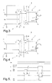
- the selector S is in a "DC” state (fig. 3) and the reversing relay A is in a "DC On” state.
- the series formed by the solenoid L and the triac T is supplied with positive direct voltage, but there is no flow of current until the gate of the triac T remains disabled.
- the microprocessor M When the microprocessor M imposes a negative voltage -3V to the gate G of the triac T (transition a in fig. 5), the latter switches into conduction and allows the flow of a current i>0 in the driven solenoid L; such a current i>0 is sufficient to induce the driven solenoid L to change state and switch to an "On" state.
- the microprocessor M thus disables the gate G of the triac T (transition b in figure 5), but the triac T continues to conduct, because the current i that flows through it is direct and different from zero.
- the microprocessor then induces the reversing relay A to switch to a "DC Off" position (transition c in figure 5), thus configuring the device 1 as in figure 4.
- the terminals 4, 6 of the series formed by the solenoid L and by the triac T are rapidly polarised at the negative voltage -Vin and in this transition the current i goes to zero, thus causing the switching off of the triac T, which prevents the flow of further current i in the driven solenoid L.
- the microprocessor induces the reversing relay A to switch back to the "DC On" position (transition d in figure 5). In this condition, the control device 1 does not consume energy.
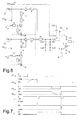
- the microprocessor enables the gate G of the triac T (transition f in figure 7), which, therefore, switches into conduction and allows the flow of a current i ⁇ 0 in the driven solenoid L.
- the flow of a sufficient current i ⁇ 0 induces the solenoid L to switch to an "Off' state.
- the triac T must still be switched off to avoid a unnecessary consumption of energy.
- the microprocessor disables the gate G of the triac T (transition g in figure 5), but the current i ⁇ 0 continues to flow in the series formed by the driven solenoid L and the triac T.
- the microprocessor (transition h in figure 5) induces the reversing relay A to switch to a "DC On" state: the terminals 4, 6 of the solenoid-triac series are rapidly polarised at a positive voltage, so that the current i goes to zero, thus forcing the switching off of the triac.
- a second embodiment is shown in fig. 6 and requires a bipolar power supply source if it is used to control a DC bistable solenoid, but allows to merely use electronic components instead of the electromechanical reversing relay A.
- the output or load terminals 4, 5 are connected to the DC bistable or AC driven solenoid L, in series to a triac T with a gate G controlled by a microprocessor M.
- the gate G requires a negative activation voltage, for example of-3V.
- the terminal 4 is connected to a switch S1, controlled by a selector S that allows to set the control device 1 for DC or AC power supply.
- Two precharge circuits PCon and PCoff are connected to two terminals Pon and Poff, connected to two outputs of the microprocessor M.
- Pon and Poff require a voltage of -3V to activate the precharge circuits PCon and PCoff.
- resistor Rc In series to the precharge circuits PCon and PCoff there is a resistor Rc.
- the capacitor Con discharges and imposes a current i>0 in the driven solenoid L, which switches to an "On" state. Unlike the previous embodiment, in this case the current i naturally goes to zero, as an effect of the discharge of the capacitor.
- the voltages +Vdc e - Vdc need to be increased.
- a voltage multiplier MT such as that shown in fig. 8, using inverter amplifiers I, capacitors C, diodes D, resistors R and a input transistor Q and in which a branch MT' generates the voltage +Vdc and the other branch MT" generates the voltage -Vdc.
- Molt is a command which enables the multiplication and must be applied at the same time respectively to the precharge controls Pon and Poff.
- a voltage multiplier circuit alternative to that in fig. 8 is shown in fig. 9 and comprises a step-up transformer TM, the secondary of which is provided with a central tap 30 at ground potential.
- the primary of the transformer M is connected to an inlet circuit which comprises a Zener diode Z, a transistor Q, a resistor R and a capacitor C and is supplied at terminal P with a variable duty-cycle square wave voltage Vp, whereas the secondary provides for the simultaneous charge of the capacitors Con and Coff.
- the capacitor Con may discharge on the solenoid L concurrently with the enabling of the gate G of the triac T, by activating the solenoid itself.
- the capacitor Coff may discharge on the solenoid L concurrently with the enabling of the gate G of the triac T, by inactivating the solenoid itself.
- the circuit with the transformer in fig. 9 halves the control times of the solenoid, by simultaneously charging Con and Coff in 10 seconds.
Landscapes
- Physics & Mathematics (AREA)
- Electromagnetism (AREA)
- Engineering & Computer Science (AREA)
- Power Engineering (AREA)
- Water Supply & Treatment (AREA)
- Life Sciences & Earth Sciences (AREA)
- Environmental Sciences (AREA)
- Control Of Electrical Variables (AREA)
- Magnetically Actuated Valves (AREA)
- Power Conversion In General (AREA)
- Valve Device For Special Equipments (AREA)
Applications Claiming Priority (1)
| Application Number | Priority Date | Filing Date | Title |
|---|---|---|---|
| IT001059A ITMI20061059A1 (it) | 2006-05-31 | 2006-05-31 | Dispositivo di controllo per il pilotaggio di per solenoidi in corrente alternata e solenoidi bistabili in corrente continua particolarmente per elettrovalvole di impianti di irrigazione |
Publications (4)
| Publication Number | Publication Date |
|---|---|
| EP1863042A2 true EP1863042A2 (fr) | 2007-12-05 |
| EP1863042A3 EP1863042A3 (fr) | 2009-06-03 |
| EP1863042A8 EP1863042A8 (fr) | 2009-07-15 |
| EP1863042B1 EP1863042B1 (fr) | 2011-11-02 |
Family
ID=38441895
Family Applications (1)
| Application Number | Title | Priority Date | Filing Date |
|---|---|---|---|
| EP07108919A Active EP1863042B1 (fr) | 2006-05-31 | 2007-05-25 | Dispositif de commande pour conduire des solénoïdes CA et des solénoïdes bistables CC, en particulier pour des électrovalves de systèmes d'irrigation |
Country Status (7)
| Country | Link |
|---|---|
| US (1) | US7701691B2 (fr) |
| EP (1) | EP1863042B1 (fr) |
| CN (1) | CN101097800B (fr) |
| AT (1) | ATE532191T1 (fr) |
| ES (1) | ES2376823T3 (fr) |
| IT (1) | ITMI20061059A1 (fr) |
| PT (1) | PT1863042E (fr) |
Cited By (2)
| Publication number | Priority date | Publication date | Assignee | Title |
|---|---|---|---|---|
| WO2009007317A1 (fr) * | 2007-07-10 | 2009-01-15 | Claber S.P.A. | Circuits de commande pour une unité de commande électronique pour systèmes d'irrigation, apte à commander des électrovannes à courant alternatif et des électrovannes bistables à courant continu |
| US12504774B2 (en) | 2023-05-19 | 2025-12-23 | Rain Bird Corporation | Activation signal for solenoids and method of activation |
Families Citing this family (9)
| Publication number | Priority date | Publication date | Assignee | Title |
|---|---|---|---|---|
| US9468162B2 (en) | 2012-08-01 | 2016-10-18 | Rain Bird Corporation | Irrigation controller wireless network adapter and networked remote service |
| EP2730159B1 (fr) | 2012-11-07 | 2019-03-20 | Rain Bird Corporation | Système de commande d'irrigation |
| US9274329B2 (en) | 2013-04-08 | 2016-03-01 | Melles-Griot | Shutter with blade damping |
| CN103292005A (zh) * | 2013-06-06 | 2013-09-11 | 南通王朝矿业设备有限公司 | 电磁阀 |
| US8851768B1 (en) | 2013-06-14 | 2014-10-07 | Melles-Griot | Shutter with power-free blade return |
| US9305729B2 (en) * | 2013-08-21 | 2016-04-05 | Littelfuse, Inc. | Capacitive driven normal relay emulator using voltage boost |
| US10609878B2 (en) | 2016-07-15 | 2020-04-07 | Rain Bird Corporation | Wireless remote irrigation control |
| CN110469699B (zh) * | 2019-08-16 | 2021-02-02 | 杭州师范大学钱江学院 | 一种可变向单向阀及其使用方法 |
| DE102019219635A1 (de) * | 2019-12-14 | 2021-06-17 | Robert Bosch Gmbh | Verfahren zum Betreiben einer Pumpe |
Family Cites Families (11)
| Publication number | Priority date | Publication date | Assignee | Title |
|---|---|---|---|---|
| US3961200A (en) * | 1973-09-06 | 1976-06-01 | John C Dute | Apparatus for constructing control circuits having relay circuit functional characteristics |
| US3885165A (en) * | 1973-10-05 | 1975-05-20 | Lawrence A Franks | Press control switch |
| US3918636A (en) * | 1974-07-23 | 1975-11-11 | Us Environment | Dual temperature controller |
| US4558391A (en) * | 1983-02-14 | 1985-12-10 | Xerox Corporation | Capacitive discharge drive for electric stapler |
| US4630166A (en) * | 1985-10-17 | 1986-12-16 | Honeywell Inc. | A.C. power control for D.C. solenoid actuators |
| CN1043698C (zh) * | 1991-09-11 | 1999-06-16 | 张凡 | 磁保持电磁铁 |
| US5740031A (en) * | 1995-09-07 | 1998-04-14 | Smart Rain Corp. Inc. | Control system for the irrigation of watering stations |
| CN2275755Y (zh) * | 1996-12-09 | 1998-03-04 | 王敬茂 | 节能电磁铁控制器 |
| US5859499A (en) * | 1997-01-15 | 1999-01-12 | Lumacell, Inc. | Emergency lighting system with a DC sensing load relay |
| US5835331A (en) * | 1997-12-03 | 1998-11-10 | Abb Power T&D Company Inc. | Half-wave drive circuit for meter disconnect switch |
| US6583997B1 (en) * | 2002-01-30 | 2003-06-24 | Square D Company | Ultra-wide input range switching power supply for circuit protection devices |
-
2006
- 2006-05-31 IT IT001059A patent/ITMI20061059A1/it unknown
-
2007
- 2007-05-25 EP EP07108919A patent/EP1863042B1/fr active Active
- 2007-05-25 ES ES07108919T patent/ES2376823T3/es active Active
- 2007-05-25 PT PT07108919T patent/PT1863042E/pt unknown
- 2007-05-25 AT AT07108919T patent/ATE532191T1/de active
- 2007-05-31 US US11/806,350 patent/US7701691B2/en not_active Expired - Fee Related
- 2007-05-31 CN CN2007101098435A patent/CN101097800B/zh not_active Expired - Fee Related
Non-Patent Citations (1)
| Title |
|---|
| None |
Cited By (2)
| Publication number | Priority date | Publication date | Assignee | Title |
|---|---|---|---|---|
| WO2009007317A1 (fr) * | 2007-07-10 | 2009-01-15 | Claber S.P.A. | Circuits de commande pour une unité de commande électronique pour systèmes d'irrigation, apte à commander des électrovannes à courant alternatif et des électrovannes bistables à courant continu |
| US12504774B2 (en) | 2023-05-19 | 2025-12-23 | Rain Bird Corporation | Activation signal for solenoids and method of activation |
Also Published As
| Publication number | Publication date |
|---|---|
| ATE532191T1 (de) | 2011-11-15 |
| ITMI20061059A1 (it) | 2007-12-01 |
| CN101097800A (zh) | 2008-01-02 |
| HK1116293A1 (en) | 2008-12-19 |
| EP1863042A3 (fr) | 2009-06-03 |
| US7701691B2 (en) | 2010-04-20 |
| EP1863042A8 (fr) | 2009-07-15 |
| ES2376823T3 (es) | 2012-03-20 |
| EP1863042B1 (fr) | 2011-11-02 |
| CN101097800B (zh) | 2012-01-04 |
| PT1863042E (pt) | 2012-02-08 |
| US20070279828A1 (en) | 2007-12-06 |
Similar Documents
| Publication | Publication Date | Title |
|---|---|---|
| EP1863042B1 (fr) | Dispositif de commande pour conduire des solénoïdes CA et des solénoïdes bistables CC, en particulier pour des électrovalves de systèmes d'irrigation | |
| EP1819641B1 (fr) | Systeme et procede de generation d'une impulsion magnetique d'excitation pour le traitement de liquides en circulation | |
| US6351366B1 (en) | Battery powered remote switch controller | |
| EP1013164B1 (fr) | Appareil électronique de control avec protection automatique contre la condition d'accumulateur épuisé pour électrovanne du type bistable, particulièrement pour des systèmes d'arrosage | |
| US10256065B2 (en) | Systems and methods for controlling relays | |
| CN105027249A (zh) | 用于控制继电器的系统和方法 | |
| US10048708B2 (en) | Power harvesting circuit employing a saturable core transformer | |
| HK1116293B (en) | A control device for driving ac solenoids and dc bistable solenoids | |
| US9786458B2 (en) | Pulse solenoid control circuit | |
| EP3005381B1 (fr) | Circuit d'excitation pour répartiteur électromagnétique | |
| US20080001560A1 (en) | Device for Driving and Electromagnet, Particularly for Operating Pumps | |
| US5737232A (en) | Power supply arrangement for a control circuit | |
| US20200044759A1 (en) | Decoder | |
| EP2175713B1 (fr) | Circuits de commande pour une unité de commande électronique pour systèmes d'irrigation, apte à commander des électrovannes à courant alternatif et des électrovannes bistables à courant continu | |
| EP1925010B1 (fr) | Circuit d'amorçage pour relais | |
| US7057871B2 (en) | Actuation circuit for an electromagnetic actuator | |
| WO2006114295A3 (fr) | Commande a phases | |
| HK1107079B (en) | System and method of generating a ringing magnetic pulse for the treatment of flowing liquids | |
| DE202005019886U1 (de) | Timer-Steckdose mit Auslösefunktion durch Induktion |
Legal Events
| Date | Code | Title | Description |
|---|---|---|---|
| PUAI | Public reference made under article 153(3) epc to a published international application that has entered the european phase |
Free format text: ORIGINAL CODE: 0009012 |
|
| AK | Designated contracting states |
Kind code of ref document: A2 Designated state(s): AT BE BG CH CY CZ DE DK EE ES FI FR GB GR HU IE IS IT LI LT LU LV MC MT NL PL PT RO SE SI SK TR |
|
| AX | Request for extension of the european patent |
Extension state: AL BA HR MK YU |
|
| PUAL | Search report despatched |
Free format text: ORIGINAL CODE: 0009013 |
|
| AK | Designated contracting states |
Kind code of ref document: A3 Designated state(s): AT BE BG CH CY CZ DE DK EE ES FI FR GB GR HU IE IS IT LI LT LU LV MC MT NL PL PT RO SE SI SK TR |
|
| AX | Request for extension of the european patent |
Extension state: AL BA HR MK RS |
|
| 17P | Request for examination filed |
Effective date: 20091127 |
|
| AKX | Designation fees paid |
Designated state(s): AT BE BG CH CY CZ DE DK EE ES FI FR GB GR HU IE IS IT LI LT LU LV MC MT NL PL PT RO SE SI SK TR |
|
| AXX | Extension fees paid |
Extension state: HR Payment date: 20091127 |
|
| 17Q | First examination report despatched |
Effective date: 20101112 |
|
| GRAP | Despatch of communication of intention to grant a patent |
Free format text: ORIGINAL CODE: EPIDOSNIGR1 |
|
| GRAS | Grant fee paid |
Free format text: ORIGINAL CODE: EPIDOSNIGR3 |
|
| GRAA | (expected) grant |
Free format text: ORIGINAL CODE: 0009210 |
|
| AK | Designated contracting states |
Kind code of ref document: B1 Designated state(s): AT BE BG CH CY CZ DE DK EE ES FI FR GB GR HU IE IS IT LI LT LU LV MC MT NL PL PT RO SE SI SK TR |
|
| AX | Request for extension of the european patent |
Extension state: HR |
|
| REG | Reference to a national code |
Ref country code: GB Ref legal event code: FG4D |
|
| REG | Reference to a national code |
Ref country code: CH Ref legal event code: EP |
|
| REG | Reference to a national code |
Ref country code: IE Ref legal event code: FG4D |
|
| REG | Reference to a national code |
Ref country code: DE Ref legal event code: R096 Ref document number: 602007018400 Country of ref document: DE Effective date: 20111229 |
|
| REG | Reference to a national code |
Ref country code: PT Ref legal event code: SC4A Free format text: AVAILABILITY OF NATIONAL TRANSLATION Effective date: 20120131 |
|
| REG | Reference to a national code |
Ref country code: NL Ref legal event code: VDEP Effective date: 20111102 |
|
| REG | Reference to a national code |
Ref country code: ES Ref legal event code: FG2A Ref document number: 2376823 Country of ref document: ES Kind code of ref document: T3 Effective date: 20120320 |
|
| LTIE | Lt: invalidation of european patent or patent extension |
Effective date: 20111102 |
|
| PG25 | Lapsed in a contracting state [announced via postgrant information from national office to epo] |
Ref country code: IS Free format text: LAPSE BECAUSE OF FAILURE TO SUBMIT A TRANSLATION OF THE DESCRIPTION OR TO PAY THE FEE WITHIN THE PRESCRIBED TIME-LIMIT Effective date: 20120302 Ref country code: LT Free format text: LAPSE BECAUSE OF FAILURE TO SUBMIT A TRANSLATION OF THE DESCRIPTION OR TO PAY THE FEE WITHIN THE PRESCRIBED TIME-LIMIT Effective date: 20111102 |
|
| PG25 | Lapsed in a contracting state [announced via postgrant information from national office to epo] |
Ref country code: PL Free format text: LAPSE BECAUSE OF FAILURE TO SUBMIT A TRANSLATION OF THE DESCRIPTION OR TO PAY THE FEE WITHIN THE PRESCRIBED TIME-LIMIT Effective date: 20111102 Ref country code: SI Free format text: LAPSE BECAUSE OF FAILURE TO SUBMIT A TRANSLATION OF THE DESCRIPTION OR TO PAY THE FEE WITHIN THE PRESCRIBED TIME-LIMIT Effective date: 20111102 Ref country code: SE Free format text: LAPSE BECAUSE OF FAILURE TO SUBMIT A TRANSLATION OF THE DESCRIPTION OR TO PAY THE FEE WITHIN THE PRESCRIBED TIME-LIMIT Effective date: 20111102 Ref country code: BE Free format text: LAPSE BECAUSE OF FAILURE TO SUBMIT A TRANSLATION OF THE DESCRIPTION OR TO PAY THE FEE WITHIN THE PRESCRIBED TIME-LIMIT Effective date: 20111102 Ref country code: GR Free format text: LAPSE BECAUSE OF FAILURE TO SUBMIT A TRANSLATION OF THE DESCRIPTION OR TO PAY THE FEE WITHIN THE PRESCRIBED TIME-LIMIT Effective date: 20120203 Ref country code: NL Free format text: LAPSE BECAUSE OF FAILURE TO SUBMIT A TRANSLATION OF THE DESCRIPTION OR TO PAY THE FEE WITHIN THE PRESCRIBED TIME-LIMIT Effective date: 20111102 Ref country code: LV Free format text: LAPSE BECAUSE OF FAILURE TO SUBMIT A TRANSLATION OF THE DESCRIPTION OR TO PAY THE FEE WITHIN THE PRESCRIBED TIME-LIMIT Effective date: 20111102 |
|
| PG25 | Lapsed in a contracting state [announced via postgrant information from national office to epo] |
Ref country code: CY Free format text: LAPSE BECAUSE OF FAILURE TO SUBMIT A TRANSLATION OF THE DESCRIPTION OR TO PAY THE FEE WITHIN THE PRESCRIBED TIME-LIMIT Effective date: 20111102 |
|
| PG25 | Lapsed in a contracting state [announced via postgrant information from national office to epo] |
Ref country code: CZ Free format text: LAPSE BECAUSE OF FAILURE TO SUBMIT A TRANSLATION OF THE DESCRIPTION OR TO PAY THE FEE WITHIN THE PRESCRIBED TIME-LIMIT Effective date: 20111102 Ref country code: EE Free format text: LAPSE BECAUSE OF FAILURE TO SUBMIT A TRANSLATION OF THE DESCRIPTION OR TO PAY THE FEE WITHIN THE PRESCRIBED TIME-LIMIT Effective date: 20111102 Ref country code: DK Free format text: LAPSE BECAUSE OF FAILURE TO SUBMIT A TRANSLATION OF THE DESCRIPTION OR TO PAY THE FEE WITHIN THE PRESCRIBED TIME-LIMIT Effective date: 20111102 Ref country code: BG Free format text: LAPSE BECAUSE OF FAILURE TO SUBMIT A TRANSLATION OF THE DESCRIPTION OR TO PAY THE FEE WITHIN THE PRESCRIBED TIME-LIMIT Effective date: 20120202 Ref country code: SK Free format text: LAPSE BECAUSE OF FAILURE TO SUBMIT A TRANSLATION OF THE DESCRIPTION OR TO PAY THE FEE WITHIN THE PRESCRIBED TIME-LIMIT Effective date: 20111102 |
|
| PG25 | Lapsed in a contracting state [announced via postgrant information from national office to epo] |
Ref country code: RO Free format text: LAPSE BECAUSE OF FAILURE TO SUBMIT A TRANSLATION OF THE DESCRIPTION OR TO PAY THE FEE WITHIN THE PRESCRIBED TIME-LIMIT Effective date: 20111102 |
|
| PLBE | No opposition filed within time limit |
Free format text: ORIGINAL CODE: 0009261 |
|
| STAA | Information on the status of an ep patent application or granted ep patent |
Free format text: STATUS: NO OPPOSITION FILED WITHIN TIME LIMIT |
|
| REG | Reference to a national code |
Ref country code: AT Ref legal event code: MK05 Ref document number: 532191 Country of ref document: AT Kind code of ref document: T Effective date: 20111102 |
|
| 26N | No opposition filed |
Effective date: 20120803 |
|
| REG | Reference to a national code |
Ref country code: DE Ref legal event code: R097 Ref document number: 602007018400 Country of ref document: DE Effective date: 20120803 |
|
| PG25 | Lapsed in a contracting state [announced via postgrant information from national office to epo] |
Ref country code: MC Free format text: LAPSE BECAUSE OF NON-PAYMENT OF DUE FEES Effective date: 20120531 |
|
| REG | Reference to a national code |
Ref country code: CH Ref legal event code: PL |
|
| PG25 | Lapsed in a contracting state [announced via postgrant information from national office to epo] |
Ref country code: AT Free format text: LAPSE BECAUSE OF FAILURE TO SUBMIT A TRANSLATION OF THE DESCRIPTION OR TO PAY THE FEE WITHIN THE PRESCRIBED TIME-LIMIT Effective date: 20111102 Ref country code: CH Free format text: LAPSE BECAUSE OF NON-PAYMENT OF DUE FEES Effective date: 20120531 Ref country code: LI Free format text: LAPSE BECAUSE OF NON-PAYMENT OF DUE FEES Effective date: 20120531 |
|
| REG | Reference to a national code |
Ref country code: IE Ref legal event code: MM4A |
|
| PG25 | Lapsed in a contracting state [announced via postgrant information from national office to epo] |
Ref country code: IE Free format text: LAPSE BECAUSE OF NON-PAYMENT OF DUE FEES Effective date: 20120525 |
|
| PG25 | Lapsed in a contracting state [announced via postgrant information from national office to epo] |
Ref country code: FI Free format text: LAPSE BECAUSE OF FAILURE TO SUBMIT A TRANSLATION OF THE DESCRIPTION OR TO PAY THE FEE WITHIN THE PRESCRIBED TIME-LIMIT Effective date: 20111102 |
|
| PG25 | Lapsed in a contracting state [announced via postgrant information from national office to epo] |
Ref country code: MT Free format text: LAPSE BECAUSE OF FAILURE TO SUBMIT A TRANSLATION OF THE DESCRIPTION OR TO PAY THE FEE WITHIN THE PRESCRIBED TIME-LIMIT Effective date: 20111102 |
|
| PGFP | Annual fee paid to national office [announced via postgrant information from national office to epo] |
Ref country code: GB Payment date: 20130424 Year of fee payment: 7 |
|
| PGFP | Annual fee paid to national office [announced via postgrant information from national office to epo] |
Ref country code: PT Payment date: 20130509 Year of fee payment: 7 |
|
| PG25 | Lapsed in a contracting state [announced via postgrant information from national office to epo] |
Ref country code: TR Free format text: LAPSE BECAUSE OF FAILURE TO SUBMIT A TRANSLATION OF THE DESCRIPTION OR TO PAY THE FEE WITHIN THE PRESCRIBED TIME-LIMIT Effective date: 20111102 |
|
| PG25 | Lapsed in a contracting state [announced via postgrant information from national office to epo] |
Ref country code: LU Free format text: LAPSE BECAUSE OF NON-PAYMENT OF DUE FEES Effective date: 20120525 |
|
| PG25 | Lapsed in a contracting state [announced via postgrant information from national office to epo] |
Ref country code: HU Free format text: LAPSE BECAUSE OF FAILURE TO SUBMIT A TRANSLATION OF THE DESCRIPTION OR TO PAY THE FEE WITHIN THE PRESCRIBED TIME-LIMIT Effective date: 20070525 |
|
| REG | Reference to a national code |
Ref country code: PT Ref legal event code: MM4A Free format text: LAPSE DUE TO NON-PAYMENT OF FEES Effective date: 20141125 |
|
| GBPC | Gb: european patent ceased through non-payment of renewal fee |
Effective date: 20140525 |
|
| PG25 | Lapsed in a contracting state [announced via postgrant information from national office to epo] |
Ref country code: PT Free format text: LAPSE BECAUSE OF NON-PAYMENT OF DUE FEES Effective date: 20141125 |
|
| REG | Reference to a national code |
Ref country code: FR Ref legal event code: PLFP Year of fee payment: 9 |
|
| PG25 | Lapsed in a contracting state [announced via postgrant information from national office to epo] |
Ref country code: GB Free format text: LAPSE BECAUSE OF NON-PAYMENT OF DUE FEES Effective date: 20140525 |
|
| PGFP | Annual fee paid to national office [announced via postgrant information from national office to epo] |
Ref country code: DE Payment date: 20150422 Year of fee payment: 9 Ref country code: ES Payment date: 20150506 Year of fee payment: 9 |
|
| PGFP | Annual fee paid to national office [announced via postgrant information from national office to epo] |
Ref country code: FR Payment date: 20150422 Year of fee payment: 9 Ref country code: IT Payment date: 20150423 Year of fee payment: 9 |
|
| REG | Reference to a national code |
Ref country code: DE Ref legal event code: R119 Ref document number: 602007018400 Country of ref document: DE |
|
| PG25 | Lapsed in a contracting state [announced via postgrant information from national office to epo] |
Ref country code: IT Free format text: LAPSE BECAUSE OF NON-PAYMENT OF DUE FEES Effective date: 20160525 |
|
| REG | Reference to a national code |
Ref country code: FR Ref legal event code: ST Effective date: 20170131 |
|
| PG25 | Lapsed in a contracting state [announced via postgrant information from national office to epo] |
Ref country code: DE Free format text: LAPSE BECAUSE OF NON-PAYMENT OF DUE FEES Effective date: 20161201 Ref country code: FR Free format text: LAPSE BECAUSE OF NON-PAYMENT OF DUE FEES Effective date: 20160531 |
|
| PG25 | Lapsed in a contracting state [announced via postgrant information from national office to epo] |
Ref country code: ES Free format text: LAPSE BECAUSE OF NON-PAYMENT OF DUE FEES Effective date: 20160526 |
|
| REG | Reference to a national code |
Ref country code: ES Ref legal event code: FD2A Effective date: 20181204 |