EP1864739A1 - Dispositif et procédé d'usinage avant traitement de roues coniques - Google Patents
Dispositif et procédé d'usinage avant traitement de roues coniques Download PDFInfo
- Publication number
- EP1864739A1 EP1864739A1 EP06115040A EP06115040A EP1864739A1 EP 1864739 A1 EP1864739 A1 EP 1864739A1 EP 06115040 A EP06115040 A EP 06115040A EP 06115040 A EP06115040 A EP 06115040A EP 1864739 A1 EP1864739 A1 EP 1864739A1
- Authority
- EP
- European Patent Office
- Prior art keywords
- bevel gear
- cutter head
- end mill
- tool
- blank
- Prior art date
- Legal status (The legal status is an assumption and is not a legal conclusion. Google has not performed a legal analysis and makes no representation as to the accuracy of the status listed.)
- Granted
Links
- 238000003754 machining Methods 0.000 title claims abstract description 31
- 238000000034 method Methods 0.000 title claims description 19
- 238000003801 milling Methods 0.000 claims abstract description 10
- 238000012545 processing Methods 0.000 claims description 17
- 238000004513 sizing Methods 0.000 claims description 11
- 238000007781 pre-processing Methods 0.000 claims description 6
- 238000012805 post-processing Methods 0.000 claims description 5
- 239000000463 material Substances 0.000 claims description 3
- 238000005096 rolling process Methods 0.000 claims description 3
- 239000002826 coolant Substances 0.000 claims description 2
- 239000000314 lubricant Substances 0.000 claims description 2
- 238000007730 finishing process Methods 0.000 claims 1
- 230000000284 resting effect Effects 0.000 claims 1
- 239000002184 metal Substances 0.000 abstract description 4
- 238000005520 cutting process Methods 0.000 abstract description 2
- 238000004519 manufacturing process Methods 0.000 description 5
- 238000006073 displacement reaction Methods 0.000 description 3
- 239000000919 ceramic Substances 0.000 description 2
- 238000010276 construction Methods 0.000 description 2
- 238000010438 heat treatment Methods 0.000 description 2
- 239000007788 liquid Substances 0.000 description 2
- 229910000831 Steel Inorganic materials 0.000 description 1
- 230000006978 adaptation Effects 0.000 description 1
- 238000013459 approach Methods 0.000 description 1
- 239000011195 cermet Substances 0.000 description 1
- 239000011248 coating agent Substances 0.000 description 1
- 238000000576 coating method Methods 0.000 description 1
- 230000001143 conditioned effect Effects 0.000 description 1
- 238000007796 conventional method Methods 0.000 description 1
- 230000001419 dependent effect Effects 0.000 description 1
- 238000013461 design Methods 0.000 description 1
- 230000001627 detrimental effect Effects 0.000 description 1
- 238000010586 diagram Methods 0.000 description 1
- 230000000694 effects Effects 0.000 description 1
- 230000009191 jumping Effects 0.000 description 1
- 230000009467 reduction Effects 0.000 description 1
- 238000011160 research Methods 0.000 description 1
- 239000010959 steel Substances 0.000 description 1
- 238000012546 transfer Methods 0.000 description 1
Images

Classifications
-
- B—PERFORMING OPERATIONS; TRANSPORTING
- B23—MACHINE TOOLS; METAL-WORKING NOT OTHERWISE PROVIDED FOR
- B23F—MAKING GEARS OR TOOTHED RACKS
- B23F17/00—Special methods or machines for making gear teeth, not covered by the preceding groups
- B23F17/006—Special methods or machines for making gear teeth, not covered by the preceding groups using different machines or machining operations
-
- B—PERFORMING OPERATIONS; TRANSPORTING
- B23—MACHINE TOOLS; METAL-WORKING NOT OTHERWISE PROVIDED FOR
- B23F—MAKING GEARS OR TOOTHED RACKS
- B23F17/00—Special methods or machines for making gear teeth, not covered by the preceding groups
- B23F17/003—Special methods or machines for making gear teeth, not covered by the preceding groups for dry cutting
-
- B—PERFORMING OPERATIONS; TRANSPORTING
- B23—MACHINE TOOLS; METAL-WORKING NOT OTHERWISE PROVIDED FOR
- B23F—MAKING GEARS OR TOOTHED RACKS
- B23F21/00—Tools specially adapted for use in machines for manufacturing gear teeth
- B23F21/005—Tools specially adapted for use in machines for manufacturing gear teeth with plural tools on a common axis
-
- B—PERFORMING OPERATIONS; TRANSPORTING
- B23—MACHINE TOOLS; METAL-WORKING NOT OTHERWISE PROVIDED FOR
- B23F—MAKING GEARS OR TOOTHED RACKS
- B23F5/00—Making straight gear teeth involving moving a tool relatively to a workpiece with a rolling-off or an enveloping motion with respect to the gear teeth to be made
- B23F5/20—Making straight gear teeth involving moving a tool relatively to a workpiece with a rolling-off or an enveloping motion with respect to the gear teeth to be made by milling
- B23F5/205—Making straight gear teeth involving moving a tool relatively to a workpiece with a rolling-off or an enveloping motion with respect to the gear teeth to be made by milling with plural tools
-
- B—PERFORMING OPERATIONS; TRANSPORTING
- B23—MACHINE TOOLS; METAL-WORKING NOT OTHERWISE PROVIDED FOR
- B23F—MAKING GEARS OR TOOTHED RACKS
- B23F9/00—Making gears having teeth curved in their longitudinal direction
- B23F9/08—Making gears having teeth curved in their longitudinal direction by milling, e.g. with helicoidal hob
-
- Y—GENERAL TAGGING OF NEW TECHNOLOGICAL DEVELOPMENTS; GENERAL TAGGING OF CROSS-SECTIONAL TECHNOLOGIES SPANNING OVER SEVERAL SECTIONS OF THE IPC; TECHNICAL SUBJECTS COVERED BY FORMER USPC CROSS-REFERENCE ART COLLECTIONS [XRACs] AND DIGESTS
- Y02—TECHNOLOGIES OR APPLICATIONS FOR MITIGATION OR ADAPTATION AGAINST CLIMATE CHANGE
- Y02P—CLIMATE CHANGE MITIGATION TECHNOLOGIES IN THE PRODUCTION OR PROCESSING OF GOODS
- Y02P70/00—Climate change mitigation technologies in the production process for final industrial or consumer products
- Y02P70/10—Greenhouse gas [GHG] capture, material saving, heat recovery or other energy efficient measures, e.g. motor control, characterised by manufacturing processes, e.g. for rolling metal or metal working
-
- Y—GENERAL TAGGING OF NEW TECHNOLOGICAL DEVELOPMENTS; GENERAL TAGGING OF CROSS-SECTIONAL TECHNOLOGIES SPANNING OVER SEVERAL SECTIONS OF THE IPC; TECHNICAL SUBJECTS COVERED BY FORMER USPC CROSS-REFERENCE ART COLLECTIONS [XRACs] AND DIGESTS
- Y10—TECHNICAL SUBJECTS COVERED BY FORMER USPC
- Y10T—TECHNICAL SUBJECTS COVERED BY FORMER US CLASSIFICATION
- Y10T29/00—Metal working
- Y10T29/49—Method of mechanical manufacture
- Y10T29/49462—Gear making
- Y10T29/49467—Gear shaping
- Y10T29/49476—Gear tooth cutting
-
- Y—GENERAL TAGGING OF NEW TECHNOLOGICAL DEVELOPMENTS; GENERAL TAGGING OF CROSS-SECTIONAL TECHNOLOGIES SPANNING OVER SEVERAL SECTIONS OF THE IPC; TECHNICAL SUBJECTS COVERED BY FORMER USPC CROSS-REFERENCE ART COLLECTIONS [XRACs] AND DIGESTS
- Y10—TECHNICAL SUBJECTS COVERED BY FORMER USPC
- Y10T—TECHNICAL SUBJECTS COVERED BY FORMER US CLASSIFICATION
- Y10T29/00—Metal working
- Y10T29/51—Plural diverse manufacturing apparatus including means for metal shaping or assembling
- Y10T29/5152—Plural diverse manufacturing apparatus including means for metal shaping or assembling with turret mechanism
- Y10T29/5154—Plural diverse manufacturing apparatus including means for metal shaping or assembling with turret mechanism tool turret
- Y10T29/5155—Rotary tool holder
-
- Y—GENERAL TAGGING OF NEW TECHNOLOGICAL DEVELOPMENTS; GENERAL TAGGING OF CROSS-SECTIONAL TECHNOLOGIES SPANNING OVER SEVERAL SECTIONS OF THE IPC; TECHNICAL SUBJECTS COVERED BY FORMER USPC CROSS-REFERENCE ART COLLECTIONS [XRACs] AND DIGESTS
- Y10—TECHNICAL SUBJECTS COVERED BY FORMER USPC
- Y10T—TECHNICAL SUBJECTS COVERED BY FORMER US CLASSIFICATION
- Y10T29/00—Metal working
- Y10T29/51—Plural diverse manufacturing apparatus including means for metal shaping or assembling
- Y10T29/5176—Plural diverse manufacturing apparatus including means for metal shaping or assembling including machining means
-
- Y—GENERAL TAGGING OF NEW TECHNOLOGICAL DEVELOPMENTS; GENERAL TAGGING OF CROSS-SECTIONAL TECHNOLOGIES SPANNING OVER SEVERAL SECTIONS OF THE IPC; TECHNICAL SUBJECTS COVERED BY FORMER USPC CROSS-REFERENCE ART COLLECTIONS [XRACs] AND DIGESTS
- Y10—TECHNICAL SUBJECTS COVERED BY FORMER USPC
- Y10T—TECHNICAL SUBJECTS COVERED BY FORMER US CLASSIFICATION
- Y10T407/00—Cutters, for shaping
- Y10T407/17—Gear cutting tool
- Y10T407/1705—Face mill gear cutting tool
- Y10T407/171—Adjustable teeth
-
- Y—GENERAL TAGGING OF NEW TECHNOLOGICAL DEVELOPMENTS; GENERAL TAGGING OF CROSS-SECTIONAL TECHNOLOGIES SPANNING OVER SEVERAL SECTIONS OF THE IPC; TECHNICAL SUBJECTS COVERED BY FORMER USPC CROSS-REFERENCE ART COLLECTIONS [XRACs] AND DIGESTS
- Y10—TECHNICAL SUBJECTS COVERED BY FORMER USPC
- Y10T—TECHNICAL SUBJECTS COVERED BY FORMER US CLASSIFICATION
- Y10T409/00—Gear cutting, milling, or planing
- Y10T409/10—Gear cutting
- Y10T409/101431—Gear tooth shape generating
- Y10T409/103816—Milling with radial faced tool
- Y10T409/103975—Process
-
- Y—GENERAL TAGGING OF NEW TECHNOLOGICAL DEVELOPMENTS; GENERAL TAGGING OF CROSS-SECTIONAL TECHNOLOGIES SPANNING OVER SEVERAL SECTIONS OF THE IPC; TECHNICAL SUBJECTS COVERED BY FORMER USPC CROSS-REFERENCE ART COLLECTIONS [XRACs] AND DIGESTS
- Y10—TECHNICAL SUBJECTS COVERED BY FORMER USPC
- Y10T—TECHNICAL SUBJECTS COVERED BY FORMER US CLASSIFICATION
- Y10T409/00—Gear cutting, milling, or planing
- Y10T409/10—Gear cutting
- Y10T409/101431—Gear tooth shape generating
- Y10T409/103816—Milling with radial faced tool
- Y10T409/104134—Adapted to cut bevel gear
-
- Y—GENERAL TAGGING OF NEW TECHNOLOGICAL DEVELOPMENTS; GENERAL TAGGING OF CROSS-SECTIONAL TECHNOLOGIES SPANNING OVER SEVERAL SECTIONS OF THE IPC; TECHNICAL SUBJECTS COVERED BY FORMER USPC CROSS-REFERENCE ART COLLECTIONS [XRACs] AND DIGESTS
- Y10—TECHNICAL SUBJECTS COVERED BY FORMER USPC
- Y10T—TECHNICAL SUBJECTS COVERED BY FORMER US CLASSIFICATION
- Y10T409/00—Gear cutting, milling, or planing
- Y10T409/10—Gear cutting
- Y10T409/101431—Gear tooth shape generating
- Y10T409/105883—Using rotary cutter
- Y10T409/106201—Plural rotary cutters
-
- Y—GENERAL TAGGING OF NEW TECHNOLOGICAL DEVELOPMENTS; GENERAL TAGGING OF CROSS-SECTIONAL TECHNOLOGIES SPANNING OVER SEVERAL SECTIONS OF THE IPC; TECHNICAL SUBJECTS COVERED BY FORMER USPC CROSS-REFERENCE ART COLLECTIONS [XRACs] AND DIGESTS
- Y10—TECHNICAL SUBJECTS COVERED BY FORMER USPC
- Y10T—TECHNICAL SUBJECTS COVERED BY FORMER US CLASSIFICATION
- Y10T409/00—Gear cutting, milling, or planing
- Y10T409/10—Gear cutting
- Y10T409/107791—Using rotary cutter
- Y10T409/10795—Process
-
- Y—GENERAL TAGGING OF NEW TECHNOLOGICAL DEVELOPMENTS; GENERAL TAGGING OF CROSS-SECTIONAL TECHNOLOGIES SPANNING OVER SEVERAL SECTIONS OF THE IPC; TECHNICAL SUBJECTS COVERED BY FORMER USPC CROSS-REFERENCE ART COLLECTIONS [XRACs] AND DIGESTS
- Y10—TECHNICAL SUBJECTS COVERED BY FORMER USPC
- Y10T—TECHNICAL SUBJECTS COVERED BY FORMER US CLASSIFICATION
- Y10T409/00—Gear cutting, milling, or planing
- Y10T409/10—Gear cutting
- Y10T409/107791—Using rotary cutter
- Y10T409/108109—End mill
-
- Y—GENERAL TAGGING OF NEW TECHNOLOGICAL DEVELOPMENTS; GENERAL TAGGING OF CROSS-SECTIONAL TECHNOLOGIES SPANNING OVER SEVERAL SECTIONS OF THE IPC; TECHNICAL SUBJECTS COVERED BY FORMER USPC CROSS-REFERENCE ART COLLECTIONS [XRACs] AND DIGESTS
- Y10—TECHNICAL SUBJECTS COVERED BY FORMER USPC
- Y10T—TECHNICAL SUBJECTS COVERED BY FORMER US CLASSIFICATION
- Y10T409/00—Gear cutting, milling, or planing
- Y10T409/10—Gear cutting
- Y10T409/107791—Using rotary cutter
- Y10T409/108586—Plural rotary cutters
-
- Y—GENERAL TAGGING OF NEW TECHNOLOGICAL DEVELOPMENTS; GENERAL TAGGING OF CROSS-SECTIONAL TECHNOLOGIES SPANNING OVER SEVERAL SECTIONS OF THE IPC; TECHNICAL SUBJECTS COVERED BY FORMER USPC CROSS-REFERENCE ART COLLECTIONS [XRACs] AND DIGESTS
- Y10—TECHNICAL SUBJECTS COVERED BY FORMER USPC
- Y10T—TECHNICAL SUBJECTS COVERED BY FORMER US CLASSIFICATION
- Y10T409/00—Gear cutting, milling, or planing
- Y10T409/30—Milling
- Y10T409/300056—Thread or helix generating
- Y10T409/300504—Plural cutters or work holders
Definitions
- the present invention relates to devices for the soft machining of bevel gears, in particular devices designed for dry machining.
- the invention also relates to a corresponding method and use of the device.
- the invention is therefore based on the object to simplify the production of large bevel gears on the one hand and on the other hand to accelerate without having to accept quality losses in the task.
- a further object of the invention is to provide a method and a corresponding device which is designed for the economic processing of large bevel gears.
- the inventive method is designed especially for the machining of tooth flanks before a hardening process, ie in the soft state. Accordingly, the tools to be used are to be selected.
- the invention can also be used for machining other gears, although the device is designed especially for large-modulus bevel gears (preferably with a module greater than 12) and is particularly economical for this particular use.
- this term also includes ring gears and bevel pinions. Also included are bevel gears without axial offset and bevel gears with axial offset, so-called hypoid gears.
- the invention primarily relates to the production of ring gears or bevel pinions with large gears.
- Such crown wheels or bevel pinions have a diameter that is greater than 1 meter and can be up to 3 meters, for example.
- the teeth can have a tooth height of up to 100 mm or more.
- the present invention is based on the following findings. There are several aspects that contribute to the cost-effectiveness of machining large bevel gears. Due to the size and weight of the workpiece, the entire handling and setting up (alignment and clamping) on a machine is very (time) consuming. Research shows that this process can take up to 2 hours. This leads to longer unproductive phases of the machine, which in turn has an impact on the economics of the overall operation.
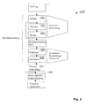
- FIG. 1 shows a schematic representation of an exemplary method sequence 100.
- the invention can be used advantageously in the context shown. It is, as mentioned, an example of the processing of a large modulus crown gear or bevel pinion.
- a blank box 101
- the following soft-machining steps are carried out in the example shown.
- a (central) bore can be created by turning (box 102).
- the blank can be turned for further processing (box 103).
- another turning operation may follow (box 104).
- These steps are optional and are referred to herein as preforming.
- preforming As part of preforming, other steps or alternate steps may be performed.
- the workpiece is referred to as a blank or workpiece blank K1.
- Step 102 or steps 102-104 may be performed, for example, in a so-called preprocessing machine or in several different machines.
- the (dry) bevel wheel milling (box 105) is preferably used as a method to perform a pre-defined number of tooth gaps on the bevel gear blank K1 in the approximate and approximate position as part of a preprocessing process with a milling cutter 14.2 (see, for example, FIG. 2) Milling up.
- the step labeled 105 is also referred to herein as (bevel gear) pre-milling.
- This is followed by the step of (bevel gear) sizing (box 106), which according to the invention is carried out with a bevel gear sizing tool 13.2 and which, by the sizing operation, gives the tooth gaps, respectively the adjacent tooth flanks, the desired shape with the given accuracy.
- the steps 105 and 106 are carried out according to the invention in one and the same machine 10.
- the workpiece blank K1 therefore does not have to be reloaded or transferred.
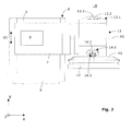
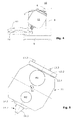
- FIGS. 2, 3 and 4 show different views, and FIG. 5 shows a schematic part of a machine 10 according to the invention.
- the machine 10 has a vertical machine part 8 with a vertically extending guide 6 (or alternatively with several guides).
- a machine part 7 is mounted laterally, along the guide (s) 6 upwards and downwards (ie parallel to the y-axis) is displaceable, as indicated by the double arrow V1.
- the machine part 8 in turn sits on a horizontal machine bed 9 and can be moved along this machine bed 9 in the z-direction, as indicated by the double arrow V2.
- the machine part 7 carries a processing arm 11 which can be pivoted about a pivot axis A1.
- This pivot axis A1 lies in Fig. 2 in the plane of the drawing, ie it is parallel to the x-axis.
- the bevel gear blank K1 to be processed lies flat (ie horizontally in the xz plane) on or in a receptacle 12 (for example in the form of a spindle or a spindle table) whose axis of rotation A2 extends parallel to the y axis.
- the machine 10 is thus a machine operating vertically or obliquely (depending on the position of the machining arm 11), in which the workpiece spindle with the wheel blank K1 is arranged below the tool spindle with the gear tool 13.2 or 14.2 during toothing.
- both the receptacle 12 and the machine bed 9 sit on a common machine platform or substructure, which is not shown in the figures.
- a first tool spindle 13.1 is provided on a first side for receiving a cutter head 13.2 serving as a bevel gear sizing tool.
- a second tool spindle 14.1 is mounted for receiving a finger milling cutter 14.2 serving as a toothing tool.
- the end mill 14.2 is shown in the pre-milling of the bevel gear blank K1, while the cutter head 13.2 points upwards and is not used.
- the machining arm 11 has a slow first drive M1 designed for larger torques and a fast second drive M2 designed for smaller torques, as indicated schematically in FIG. 5 by means of two circles.
- These drives M1 and M2 include motors, which preferably sit in the processing arm 11, and if necessary, over- or reductions. It is also possible to accommodate a part of the drives at a different location of the machine 10 and to guide the rotational movement in the processing arm 11 and from there to the spindles 13.1 and 14.1 by means of shafts.
- the whole arrangement is designed so that the first tool spindle 13.1 can be driven by the first drive M1 and the second tool spindle 14.1 by the second drive, normally either one or the other drive is in function.
- a single motor can be provided, which drives both spindles 13.1 and 14.1 alternately, in which case the necessary speed is provided by appropriate drive trains.
- the bevel gear finishing tool is driven at a speed of less than 100 rpm and the end mill is driven at a speed between 800 and 2500 rpm.
- the machine 10 comprises a CNC control S, as indicated schematically in FIG. 2, or the machine 10 is connected to an external CNC control S.
- the CNC control S is programmed so that it controls the individual movement sequences according to the invention.
- the end mill 14.2 is set in rapid rotation by means of the second drive M2 and the machine axes are moved (called infeed movement) such that the end mill 14.2 dips into the workpiece blank K1 and in a generating pre-processing process engages the bevel gear blank K1 edited the end mill 14.2.
- a 3-dimensional relative movement between the end mill 14.2 and workpiece blank K1 is carried out such that a predefined number of tooth gaps with a predefined shape are cut or milled on the bevel wheel blank K1 in the approximate position and with approximate dimensions.
- Vorbearbeitungsreaes is milled at the bevel gear blank K1 with the end mill 14.2 between 50% and 95% of the material in the range of tooth gaps to be produced before then the Postprocessing process. It is therefore a roughing or broaching. Since it is not an exact production of the tooth gaps but only a pre-processing, it is thus not particularly critical when the end mill 14.2 shows certain signs of wear, since this has no or only a small effect on the subsequent post-processing.
- the end mill 14.2 does not have to meet particularly high requirements. It can be used in most cases, a standard end mill or a suitable variant, which is relatively cheap. If the end mill 14.2 worn, it can be replaced with a few simple steps.
- the spindle 14.1 preferably has a quick-release device. The construction of the machine 10 even makes it possible to replace the end mill 14.2 while finishing with the tool 13.2.
- the end mill 14.2 preferably has a conical or trapezoidal cross-section in an axial plane, as can be seen, for example, in FIG. Particularly preferred are end mill 14.2 made of hard metal.
- the end mill 14.2 may have one or more cut edges 14.3. In Fig. 3, several such cut edges can be seen. It can also be seen from the figures that the end mill 14.2 has a significantly smaller diameter than the cutter head 13.2 serving as a bevel gear sizing tool. Preferably, the diameter of the end mill 14.2 is less than 20% of the diameter of the cutter head 13.1. It should be noted that the end mill 14.2 must be smaller than the gap that it creates.
- Bevel gear sizing tools with a diameter of between 500 and 1300 mm are advantageously used, while the end mill can typically have a circumference at the bottom end of the cone between 10 and 25 mm and at the top end between 80 and 100 mm.
- the end mill is preferably guided only on a track which corresponds approximately to the gap and thereby generates a shape corresponding to its shape Tooth profile.
- the final profile of the teeth is created by finishing with the knife head.
- the bevel gear blank K1 can easily rotate about the workpiece axis A2 during the preprocessing of each tooth gap, or the bevel gear blank K1 can rest during the pre-machining of each tooth gap. When jumping to the next tooth gap to be produced then makes the Kegelradrohling K1 always a so-called pitch rotational movement about the workpiece axis A2.
- a workpiece drive M3 is provided, which allows a controlled controlled rotation about the workpiece axis A2.
- the corresponding drive M3 is indicated schematically in FIG.
- the second tool used in the same machine 10 is, as already mentioned, a cutter head 13.2 serving as a bevel gear sizing tool.
- This cutter head 13.2 is equipped with a plurality of blades 13.3, which are shaped and arranged so that they perform a finishing operation when immersed in the workpiece blank K1 with prefabricated tooth spaces.
- the cutter head 13.2 makes a rotary movement about the spindle axis S1 and, on the other hand, the bevel gear blank K1 also rotates about the workpiece axis A2. This leads to a generating rolling motion between the cutting edges of the knives 13.3 and the bevel gear blank K1. Also, it can be finished in a continuous or single-part method.
- the knives 13.3 of the cutter head 13.2 are directed axially towards the cutter head 13.2 (i.e., they are parallel to the spindle axis S1), as can be seen, for example, in FIG.
- tools of high-performance steel, of hard metal, of ceramic, or of cermet (combination of metal and ceramic), each with a suitable hard material coating are used according to the invention for machining bevel gear teeth.
- the embodiment shown and described is a 6-axis machine 10 that allows relative movements in multiple directions. Namely, the following movements are possible: (lateral) displacement V1, (horizontal) displacement V2, pivotal movement about A1, rotation of the first tool 13.2 about the spindle axis S1, rotation of the second tool 14.2 about the spindle axis S2, and rotation of the workpiece K1 about the axis A2.
- one or both movements in the y-z plane and in the x-z plane may be performed by translating the bevel gear blank K1. In this case, a displacement V1 or V2 is no longer necessary.
- the different axes are numerically controlled axes.
- the individual movements can be numerically controlled by the CNC control S.
- the controller S is designed so that all axes are controlled numerically controlled. It is important that some of the movements are coordinated. This coordination is done by the CNC S controller.
- the heavy and large bevel gear blank K1 can easily be fed and removed by means of a crane or other lifting means.
- a finger mill 14.2 is advantageous because such cutters are particularly predestined to work in the full, i. in other words, to be used for roughing or broaching.
- end mills 14.2 which are easy to maintain. Also, it is easier and less expensive to realize a high-speed drive M2 for a small-diameter end mill 14.2 than a corresponding high-speed drive for a large and heavy blade head 13.2. Furthermore, as mentioned, the tool change easier and faster. In addition, the forces acting on the machine 10 are significantly lower during rough machining.
Landscapes
- Engineering & Computer Science (AREA)
- Mechanical Engineering (AREA)
- Gear Processing (AREA)
- Gear Transmission (AREA)
- Milling Processes (AREA)
- Gears, Cams (AREA)
Priority Applications (8)
| Application Number | Priority Date | Filing Date | Title |
|---|---|---|---|
| ES06115040T ES2322715T3 (es) | 2006-06-06 | 2006-06-06 | Dispositivo y procedimiento para la mecanizacion blanda de ruedas conicas y utilizacion del dispositivo. |
| DE502006003095T DE502006003095D1 (de) | 2006-06-06 | 2006-06-06 | Vorrichtung und Verfahren zur Weichbearbeitung von Kegelrädern und Verwendung der Vorrichtung |
| EP06115040A EP1864739B1 (fr) | 2006-06-06 | 2006-06-06 | Dispositif et procédé d'usinage avant traitement de roues coniques |
| AT06115040T ATE424960T1 (de) | 2006-06-06 | 2006-06-06 | Vorrichtung und verfahren zur weichbearbeitung von kegelrädern und verwendung der vorrichtung |
| US11/757,587 US7461441B2 (en) | 2006-06-06 | 2007-06-04 | Device and method for soft machining of bevel gears and use of the device |
| CN200710109890XA CN101085481B (zh) | 2006-06-06 | 2007-06-05 | 软加工锥齿轮的装置和方法及该装置的应用 |
| JP2007150496A JP4833153B2 (ja) | 2006-06-06 | 2007-06-06 | ベベルギヤの軟式機械加工のための装置及び方法並びに該装置の使用方法 |
| US12/264,569 US7574798B2 (en) | 2006-06-06 | 2008-11-04 | Method for soft machining of bevel gears |
Applications Claiming Priority (1)
| Application Number | Priority Date | Filing Date | Title |
|---|---|---|---|
| EP06115040A EP1864739B1 (fr) | 2006-06-06 | 2006-06-06 | Dispositif et procédé d'usinage avant traitement de roues coniques |
Publications (2)
| Publication Number | Publication Date |
|---|---|
| EP1864739A1 true EP1864739A1 (fr) | 2007-12-12 |
| EP1864739B1 EP1864739B1 (fr) | 2009-03-11 |
Family
ID=37056822
Family Applications (1)
| Application Number | Title | Priority Date | Filing Date |
|---|---|---|---|
| EP06115040A Not-in-force EP1864739B1 (fr) | 2006-06-06 | 2006-06-06 | Dispositif et procédé d'usinage avant traitement de roues coniques |
Country Status (7)
| Country | Link |
|---|---|
| US (2) | US7461441B2 (fr) |
| EP (1) | EP1864739B1 (fr) |
| JP (1) | JP4833153B2 (fr) |
| CN (1) | CN101085481B (fr) |
| AT (1) | ATE424960T1 (fr) |
| DE (1) | DE502006003095D1 (fr) |
| ES (1) | ES2322715T3 (fr) |
Cited By (4)
| Publication number | Priority date | Publication date | Assignee | Title |
|---|---|---|---|---|
| CN102029443A (zh) * | 2011-01-06 | 2011-04-27 | 山东伊莱特重工有限公司 | Φ5米-φ8米弧齿锥齿轮铣齿机床 |
| WO2011087759A1 (fr) * | 2009-12-22 | 2011-07-21 | The Gleason Works | Procédé et appareil pour la fabrication d'engrenages coniques |
| CN102151909A (zh) * | 2011-03-18 | 2011-08-17 | 陕西秦川机械发展股份有限公司 | 大型数控齿轮加工机床 |
| CN103092130A (zh) * | 2013-02-01 | 2013-05-08 | 湖南江滨机器(集团)有限责任公司 | 一种活塞外圆建模方法 |
Families Citing this family (22)
| Publication number | Priority date | Publication date | Assignee | Title |
|---|---|---|---|---|
| JP2008529810A (ja) * | 2005-02-14 | 2008-08-07 | クリンゲルンベルク・ゲゼルシャフト・ミット・ベシュレンクテル・ハフツング | 傘歯車の硬化前機械加工を行うための装置及び方法 |
| EP1864739B1 (fr) * | 2006-06-06 | 2009-03-11 | Klingelnberg GmbH | Dispositif et procédé d'usinage avant traitement de roues coniques |
| DE502007002752D1 (de) * | 2007-09-12 | 2010-03-18 | Klingelnberg Ag | Verfahren zum diskontinuierlichen Schleifen von Kegelrädern und entsprechende Software zum Steuern einer mehrachsigen Schleifmaschine |
| JP5661620B2 (ja) * | 2008-06-23 | 2015-01-28 | ザ グリーソン ワークス | かさ歯車の製造 |
| WO2011001517A1 (fr) * | 2009-06-30 | 2011-01-06 | ヤマザキマザック株式会社 | Tour de travail composite |
| CN101733486B (zh) * | 2010-01-18 | 2012-09-19 | 天津大学 | 圆柱齿轮剐齿加工方法 |
| DE102010023728A1 (de) * | 2010-06-14 | 2011-12-15 | Liebherr-Verzahntechnik Gmbh | Verfahren zum Herstellen einer Mehrzahl von identischen Zahnrädern mittles abspanender Bearbeitung |
| DE102011017411A1 (de) * | 2011-04-18 | 2012-10-18 | Liebherr-Verzahntechnik Gmbh | Verzahnmaschine, Fingerfräser und Verfahren zum Formfräsen |
| US20120290120A1 (en) * | 2011-05-03 | 2012-11-15 | Douglas Cameron Dayton | Three Axis Desktop Machining Center with a Simplified Mechanism for Low Cost Implementation |
| DE102011076835A1 (de) | 2011-05-31 | 2012-12-06 | Gildemeister Italiana S.P.A. | Werkzeugträger und Werkzeugmaschine mit einem Werkzeugträger |
| EP2535134B1 (fr) * | 2011-06-16 | 2018-01-24 | Klingelnberg AG | Procédé pour pré-tailler plusieurs roues coniques différentes |
| JP5761577B2 (ja) * | 2012-06-22 | 2015-08-12 | アイシン精機株式会社 | クラウンギヤの製造装置及び製造方法 |
| JP6140585B2 (ja) * | 2013-09-19 | 2017-05-31 | 三菱重工工作機械株式会社 | 内歯車加工機械及び内歯車加工方法 |
| KR20150077660A (ko) * | 2013-12-30 | 2015-07-08 | 현대다이모스(주) | 고주파 열처리 소재 및 이를 이용한 기어 제조 방법 |
| DE102014014132A1 (de) * | 2014-09-30 | 2016-05-25 | Liebherr-Verzahntechnik Gmbh | Verfahren und Vorrichtung zum Anfasen und Entgraten verzahnter Werkstücke |
| US10315254B2 (en) * | 2015-02-23 | 2019-06-11 | Ford Motor Company | Method of machining dissimilar materials |
| EP3375555B1 (fr) * | 2017-03-17 | 2024-07-24 | Klingelnberg AG | Procédé de traitement des flancs de dent de pièces de roue dentée conique |
| CN108971658A (zh) * | 2017-06-01 | 2018-12-11 | 重庆瀚源机械有限公司 | 一种能够调节转速的铣齿机 |
| CN107877106A (zh) * | 2017-11-14 | 2018-04-06 | 北京大圣格尔冶金设备有限公司 | 一种推压齿轮齿的加工工艺方法 |
| CN108274208B (zh) * | 2018-04-20 | 2020-03-27 | 浙江威肯特智能机械有限公司 | 一种大模数少齿数齿轮加工工艺 |
| EP3801964B1 (fr) * | 2018-05-25 | 2024-09-11 | The Gleason Works | Dispositif de chanfreinage multi-outil destiné à des pièces dentées |
| CN120115759B (zh) * | 2025-05-15 | 2025-08-12 | 山东沪金精工科技股份有限公司 | 一种工件磨削装置及方法 |
Citations (4)
| Publication number | Priority date | Publication date | Assignee | Title |
|---|---|---|---|---|
| DD88716A (fr) * | ||||
| JPS61168420A (ja) * | 1985-01-22 | 1986-07-30 | Takeo Inoue | 創成歯切法に基づき,大モジユ−ルmp18〜mp120位,大ベベルギヤ−の歯切及び,歯研削を行う方法 |
| DE9412276U1 (de) * | 1994-07-29 | 1995-08-24 | Hurth Modul GmbH, 09125 Chemnitz | Maschine zum Herstellen oder Bearbeiten von Kegelrädern |
| DE10124779A1 (de) * | 2000-05-22 | 2001-11-29 | Dana Corp | Verfahren zum spanabhebenden Bearbeiten von Hypoidzahnrädern |
Family Cites Families (18)
| Publication number | Priority date | Publication date | Assignee | Title |
|---|---|---|---|---|
| DE88716C (fr) | ||||
| JPS51126586A (en) * | 1975-04-28 | 1976-11-04 | Toyoda Mach Works Ltd | Device for stopping the spindle of turret type machining center in fix ed phase |
| JPS59191246U (ja) * | 1983-06-02 | 1984-12-19 | 三興機械株式会社 | 研削機 |
| US5255475A (en) * | 1985-12-13 | 1993-10-26 | Oerlikon Geartec Ag | Tool for grinding the teeth of bevel gears having longitudinally curved teeth |
| FR2641220B1 (fr) * | 1988-05-25 | 1994-06-03 | Somab Sa | Machine-outil multifonctions permettant des usinages complexes de pieces longues |
| US5007151A (en) * | 1988-10-26 | 1991-04-16 | The Monarch Machine Tool Company | Machine tool turret |
| ES2068879T3 (es) * | 1989-01-06 | 1995-05-01 | Eaton Corp | Metodo para realizar coronas dentadas y las coronas dentadas del mismo. |
| DE19516985A1 (de) * | 1995-05-09 | 1996-11-14 | Sauter Kg Feinmechanik | Werkzeugrevolver |
| DE19517358C1 (de) * | 1995-05-11 | 1996-10-24 | Klingelnberg Soehne | Verfahren zum Fertigbearbeiten der gehärteten Verzahnung eines Kegelrades |
| CN2242150Y (zh) * | 1995-12-21 | 1996-12-11 | 李洪喜 | 铣磨装置 |
| DE19618757C2 (de) * | 1996-05-09 | 2001-02-22 | Witzig & Frank Turmatic Gmbh | Werkzeugmaschine |
| USRE38504E1 (en) * | 1996-11-08 | 2004-04-20 | Klingelnberg Gmbh | Machine for producing spiral-toothed bevel gears |
| FR2758488B1 (fr) * | 1997-01-20 | 1999-02-12 | Jean Michel Delacou | Dispositif d'usinage par enlevement de copeaux, a bloc massif et colonne coulissante et machine incorporant ce dispositif |
| JP2000052144A (ja) * | 1998-08-11 | 2000-02-22 | Ishikawajima Harima Heavy Ind Co Ltd | カービックカップリングの製作方法及び装置 |
| DE19837858A1 (de) * | 1998-08-20 | 2000-03-02 | Wacker Siltronic Halbleitermat | Schleifmaschine |
| JP2002144149A (ja) * | 2000-11-09 | 2002-05-21 | Yutaka Seimitsu Kogyo Ltd | 歯切装置 |
| DE10240509C5 (de) * | 2002-09-03 | 2017-04-27 | Reishauer Ag | Verzahnungs- und Gewindeschleifmaschine |
| EP1864739B1 (fr) * | 2006-06-06 | 2009-03-11 | Klingelnberg GmbH | Dispositif et procédé d'usinage avant traitement de roues coniques |
-
2006
- 2006-06-06 EP EP06115040A patent/EP1864739B1/fr not_active Not-in-force
- 2006-06-06 DE DE502006003095T patent/DE502006003095D1/de active Active
- 2006-06-06 ES ES06115040T patent/ES2322715T3/es active Active
- 2006-06-06 AT AT06115040T patent/ATE424960T1/de active
-
2007
- 2007-06-04 US US11/757,587 patent/US7461441B2/en not_active Expired - Fee Related
- 2007-06-05 CN CN200710109890XA patent/CN101085481B/zh not_active Expired - Fee Related
- 2007-06-06 JP JP2007150496A patent/JP4833153B2/ja not_active Expired - Fee Related
-
2008
- 2008-11-04 US US12/264,569 patent/US7574798B2/en not_active Expired - Fee Related
Patent Citations (4)
| Publication number | Priority date | Publication date | Assignee | Title |
|---|---|---|---|---|
| DD88716A (fr) * | ||||
| JPS61168420A (ja) * | 1985-01-22 | 1986-07-30 | Takeo Inoue | 創成歯切法に基づき,大モジユ−ルmp18〜mp120位,大ベベルギヤ−の歯切及び,歯研削を行う方法 |
| DE9412276U1 (de) * | 1994-07-29 | 1995-08-24 | Hurth Modul GmbH, 09125 Chemnitz | Maschine zum Herstellen oder Bearbeiten von Kegelrädern |
| DE10124779A1 (de) * | 2000-05-22 | 2001-11-29 | Dana Corp | Verfahren zum spanabhebenden Bearbeiten von Hypoidzahnrädern |
Cited By (7)
| Publication number | Priority date | Publication date | Assignee | Title |
|---|---|---|---|---|
| WO2011087759A1 (fr) * | 2009-12-22 | 2011-07-21 | The Gleason Works | Procédé et appareil pour la fabrication d'engrenages coniques |
| US9289839B2 (en) | 2009-12-22 | 2016-03-22 | The Gleason Works | Method for manufacturing bevel gears |
| CN102029443A (zh) * | 2011-01-06 | 2011-04-27 | 山东伊莱特重工有限公司 | Φ5米-φ8米弧齿锥齿轮铣齿机床 |
| CN102029443B (zh) * | 2011-01-06 | 2012-11-21 | 山东伊莱特重工有限公司 | Φ5米-φ8米弧齿锥齿轮铣齿机床 |
| CN102151909A (zh) * | 2011-03-18 | 2011-08-17 | 陕西秦川机械发展股份有限公司 | 大型数控齿轮加工机床 |
| CN102151909B (zh) * | 2011-03-18 | 2012-12-05 | 陕西秦川机械发展股份有限公司 | 大型数控齿轮加工机床 |
| CN103092130A (zh) * | 2013-02-01 | 2013-05-08 | 湖南江滨机器(集团)有限责任公司 | 一种活塞外圆建模方法 |
Also Published As
| Publication number | Publication date |
|---|---|
| US7574798B2 (en) | 2009-08-18 |
| CN101085481A (zh) | 2007-12-12 |
| ES2322715T3 (es) | 2009-06-25 |
| US7461441B2 (en) | 2008-12-09 |
| US20090060671A1 (en) | 2009-03-05 |
| ATE424960T1 (de) | 2009-03-15 |
| EP1864739B1 (fr) | 2009-03-11 |
| JP4833153B2 (ja) | 2011-12-07 |
| US20070283545A1 (en) | 2007-12-13 |
| JP2007326213A (ja) | 2007-12-20 |
| DE502006003095D1 (de) | 2009-04-23 |
| CN101085481B (zh) | 2011-02-16 |
Similar Documents
| Publication | Publication Date | Title |
|---|---|---|
| EP1864739B1 (fr) | Dispositif et procédé d'usinage avant traitement de roues coniques | |
| EP3552743B1 (fr) | Dispositif et procédé de chanfreinage d'une pièce dentée | |
| EP2385885B2 (fr) | Dispositif et procédé pour tailler des dents dans des pièces | |
| EP1598137B1 (fr) | Machine de taillage de roues dentées coniques pour chanfreiner et/ou ébavurer une roue dentée ainsi qu'un procédé correspondant | |
| EP2570217B1 (fr) | Procédé d'écroutage semi-complet et dispositif doté d'un outil d'écroutage associé pour développer un procédé d'écroutage semi-complet | |
| EP2823924B1 (fr) | Machine à dresser double | |
| DE10330474B4 (de) | Vorrichtung zur Herstellung eines Zahnrads aus einem Zahnradrohling | |
| EP3299105B1 (fr) | Procédé de chanfreinage des roues dentées coniques | |
| EP3546101B1 (fr) | Procédé et dispositif servant à tailler des roues d'usinage par décolletage en développante | |
| EP3412393B1 (fr) | Dispositifs et procédé de chanfreinage d'une pièce à denture intérieure | |
| EP3388179A1 (fr) | Procédé d'usinage de denture d'une pièce à usiner | |
| EP2786824A2 (fr) | Dispositifs et procédé de chanfreinage d'une pièce | |
| WO2016091356A1 (fr) | Procédé de traitement d'une denture, ensemble d'outil et machine à denture | |
| DE102015002362A1 (de) | Bearbeitungskopf für eine Verzahnmaschine und Verfahren zur Verzahnung eines Werkstückes, insbesondere einer Schneckenwelle oder Zahnstange | |
| EP1850994A1 (fr) | Procede et dispositif d'usinage avant traitement de roues coniques | |
| DE102017107999A1 (de) | Entgratvorrichtung sowie CNC-Verzahnmaschine mit einer solchen Entgratvorrichtung | |
| DE805344C (de) | Nach dem Abwaelzverfahren arbeitende Verzahnungsmaschine | |
| DE102007039959B4 (de) | Verfahren zum Kaltwalzen von längsgerichteten Verzahnungen und Profilen bei langen wellenförmigen Werkstücken und Profilwalzmaschine hierzu | |
| DE20320294U1 (de) | Vorrichtung zur Herstellung eines Zahnrads | |
| DE19918289A1 (de) | Verfahren zum Herstellen verzahnter Werkstücke | |
| DE10230148A1 (de) | Verfahren zum Bearbeiten von mittels Wälzfräsen hergestellten Zahnrädern | |
| EP2864075B1 (fr) | Procédé de traitement d'une pièce et machine à tailler les engrenages correspondante | |
| EP3511100B1 (fr) | Procédé destiné à tailler des pièces à usiner formant roue conique | |
| WO2024099987A1 (fr) | Procédé d'usinage de denture avec chanfreinage ultérieur | |
| DE1034951B (de) | Nach dem Abwaelzverfahren arbeitende Kegelrad-Verzahnungsmaschine zur Herstellung profilkorrigierter Verzahnungen |
Legal Events
| Date | Code | Title | Description |
|---|---|---|---|
| PUAI | Public reference made under article 153(3) epc to a published international application that has entered the european phase |
Free format text: ORIGINAL CODE: 0009012 |
|
| AK | Designated contracting states |
Kind code of ref document: A1 Designated state(s): AT BE BG CH CY CZ DE DK EE ES FI FR GB GR HU IE IS IT LI LT LU LV MC NL PL PT RO SE SI SK TR |
|
| AX | Request for extension of the european patent |
Extension state: AL BA HR MK YU |
|
| 17P | Request for examination filed |
Effective date: 20080125 |
|
| AKX | Designation fees paid |
Designated state(s): AT BE BG CH CY CZ DE DK EE ES FI FR GB GR HU IE IS IT LI LT LU LV MC NL PL PT RO SE SI SK TR |
|
| GRAP | Despatch of communication of intention to grant a patent |
Free format text: ORIGINAL CODE: EPIDOSNIGR1 |
|
| GRAS | Grant fee paid |
Free format text: ORIGINAL CODE: EPIDOSNIGR3 |
|
| GRAS | Grant fee paid |
Free format text: ORIGINAL CODE: EPIDOSNIGR3 |
|
| GRAA | (expected) grant |
Free format text: ORIGINAL CODE: 0009210 |
|
| AK | Designated contracting states |
Kind code of ref document: B1 Designated state(s): AT BE BG CH CY CZ DE DK EE ES FI FR GB GR HU IE IS IT LI LT LU LV MC NL PL PT RO SE SI SK TR |
|
| REG | Reference to a national code |
Ref country code: GB Ref legal event code: FG4D Free format text: NOT ENGLISH |
|
| REG | Reference to a national code |
Ref country code: CH Ref legal event code: EP |
|
| REG | Reference to a national code |
Ref country code: CH Ref legal event code: NV Representative=s name: OK PAT AG PATENTE MARKEN LIZENZEN |
|
| REG | Reference to a national code |
Ref country code: IE Ref legal event code: FG4D Free format text: LANGUAGE OF EP DOCUMENT: GERMAN |
|
| REF | Corresponds to: |
Ref document number: 502006003095 Country of ref document: DE Date of ref document: 20090423 Kind code of ref document: P |
|
| REG | Reference to a national code |
Ref country code: ES Ref legal event code: FG2A Ref document number: 2322715 Country of ref document: ES Kind code of ref document: T3 |
|
| REG | Reference to a national code |
Ref country code: SE Ref legal event code: TRGR |
|
| PG25 | Lapsed in a contracting state [announced via postgrant information from national office to epo] |
Ref country code: LT Free format text: LAPSE BECAUSE OF FAILURE TO SUBMIT A TRANSLATION OF THE DESCRIPTION OR TO PAY THE FEE WITHIN THE PRESCRIBED TIME-LIMIT Effective date: 20090311 Ref country code: SI Free format text: LAPSE BECAUSE OF FAILURE TO SUBMIT A TRANSLATION OF THE DESCRIPTION OR TO PAY THE FEE WITHIN THE PRESCRIBED TIME-LIMIT Effective date: 20090311 |
|
| PG25 | Lapsed in a contracting state [announced via postgrant information from national office to epo] |
Ref country code: LV Free format text: LAPSE BECAUSE OF FAILURE TO SUBMIT A TRANSLATION OF THE DESCRIPTION OR TO PAY THE FEE WITHIN THE PRESCRIBED TIME-LIMIT Effective date: 20090311 Ref country code: PL Free format text: LAPSE BECAUSE OF FAILURE TO SUBMIT A TRANSLATION OF THE DESCRIPTION OR TO PAY THE FEE WITHIN THE PRESCRIBED TIME-LIMIT Effective date: 20090311 |
|
| REG | Reference to a national code |
Ref country code: IE Ref legal event code: FD4D |
|
| PG25 | Lapsed in a contracting state [announced via postgrant information from national office to epo] |
Ref country code: PT Free format text: LAPSE BECAUSE OF FAILURE TO SUBMIT A TRANSLATION OF THE DESCRIPTION OR TO PAY THE FEE WITHIN THE PRESCRIBED TIME-LIMIT Effective date: 20090824 Ref country code: CZ Free format text: LAPSE BECAUSE OF FAILURE TO SUBMIT A TRANSLATION OF THE DESCRIPTION OR TO PAY THE FEE WITHIN THE PRESCRIBED TIME-LIMIT Effective date: 20090311 Ref country code: IE Free format text: LAPSE BECAUSE OF FAILURE TO SUBMIT A TRANSLATION OF THE DESCRIPTION OR TO PAY THE FEE WITHIN THE PRESCRIBED TIME-LIMIT Effective date: 20090311 Ref country code: EE Free format text: LAPSE BECAUSE OF FAILURE TO SUBMIT A TRANSLATION OF THE DESCRIPTION OR TO PAY THE FEE WITHIN THE PRESCRIBED TIME-LIMIT Effective date: 20090311 |
|
| PG25 | Lapsed in a contracting state [announced via postgrant information from national office to epo] |
Ref country code: SK Free format text: LAPSE BECAUSE OF FAILURE TO SUBMIT A TRANSLATION OF THE DESCRIPTION OR TO PAY THE FEE WITHIN THE PRESCRIBED TIME-LIMIT Effective date: 20090311 Ref country code: RO Free format text: LAPSE BECAUSE OF FAILURE TO SUBMIT A TRANSLATION OF THE DESCRIPTION OR TO PAY THE FEE WITHIN THE PRESCRIBED TIME-LIMIT Effective date: 20090311 Ref country code: IS Free format text: LAPSE BECAUSE OF FAILURE TO SUBMIT A TRANSLATION OF THE DESCRIPTION OR TO PAY THE FEE WITHIN THE PRESCRIBED TIME-LIMIT Effective date: 20090711 |
|
| PLBE | No opposition filed within time limit |
Free format text: ORIGINAL CODE: 0009261 |
|
| STAA | Information on the status of an ep patent application or granted ep patent |
Free format text: STATUS: NO OPPOSITION FILED WITHIN TIME LIMIT |
|
| PG25 | Lapsed in a contracting state [announced via postgrant information from national office to epo] |
Ref country code: MC Free format text: LAPSE BECAUSE OF NON-PAYMENT OF DUE FEES Effective date: 20090630 Ref country code: BG Free format text: LAPSE BECAUSE OF FAILURE TO SUBMIT A TRANSLATION OF THE DESCRIPTION OR TO PAY THE FEE WITHIN THE PRESCRIBED TIME-LIMIT Effective date: 20090611 Ref country code: DK Free format text: LAPSE BECAUSE OF FAILURE TO SUBMIT A TRANSLATION OF THE DESCRIPTION OR TO PAY THE FEE WITHIN THE PRESCRIBED TIME-LIMIT Effective date: 20090311 |
|
| 26N | No opposition filed |
Effective date: 20091214 |
|
| PG25 | Lapsed in a contracting state [announced via postgrant information from national office to epo] |
Ref country code: GR Free format text: LAPSE BECAUSE OF FAILURE TO SUBMIT A TRANSLATION OF THE DESCRIPTION OR TO PAY THE FEE WITHIN THE PRESCRIBED TIME-LIMIT Effective date: 20090612 |
|
| PG25 | Lapsed in a contracting state [announced via postgrant information from national office to epo] |
Ref country code: LU Free format text: LAPSE BECAUSE OF NON-PAYMENT OF DUE FEES Effective date: 20090606 |
|
| PG25 | Lapsed in a contracting state [announced via postgrant information from national office to epo] |
Ref country code: HU Free format text: LAPSE BECAUSE OF FAILURE TO SUBMIT A TRANSLATION OF THE DESCRIPTION OR TO PAY THE FEE WITHIN THE PRESCRIBED TIME-LIMIT Effective date: 20090912 |
|
| PG25 | Lapsed in a contracting state [announced via postgrant information from national office to epo] |
Ref country code: TR Free format text: LAPSE BECAUSE OF FAILURE TO SUBMIT A TRANSLATION OF THE DESCRIPTION OR TO PAY THE FEE WITHIN THE PRESCRIBED TIME-LIMIT Effective date: 20090311 |
|
| PG25 | Lapsed in a contracting state [announced via postgrant information from national office to epo] |
Ref country code: CY Free format text: LAPSE BECAUSE OF FAILURE TO SUBMIT A TRANSLATION OF THE DESCRIPTION OR TO PAY THE FEE WITHIN THE PRESCRIBED TIME-LIMIT Effective date: 20090311 |
|
| REG | Reference to a national code |
Ref country code: FR Ref legal event code: PLFP Year of fee payment: 11 |
|
| PGFP | Annual fee paid to national office [announced via postgrant information from national office to epo] |
Ref country code: FI Payment date: 20160613 Year of fee payment: 11 Ref country code: ES Payment date: 20160614 Year of fee payment: 11 Ref country code: CH Payment date: 20160620 Year of fee payment: 11 Ref country code: DE Payment date: 20160621 Year of fee payment: 11 Ref country code: GB Payment date: 20160621 Year of fee payment: 11 |
|
| PGFP | Annual fee paid to national office [announced via postgrant information from national office to epo] |
Ref country code: NL Payment date: 20160620 Year of fee payment: 11 Ref country code: BE Payment date: 20160620 Year of fee payment: 11 Ref country code: SE Payment date: 20160620 Year of fee payment: 11 Ref country code: AT Payment date: 20160621 Year of fee payment: 11 Ref country code: FR Payment date: 20160627 Year of fee payment: 11 |
|
| PGFP | Annual fee paid to national office [announced via postgrant information from national office to epo] |
Ref country code: IT Payment date: 20160628 Year of fee payment: 11 |
|
| REG | Reference to a national code |
Ref country code: DE Ref legal event code: R119 Ref document number: 502006003095 Country of ref document: DE |
|
| REG | Reference to a national code |
Ref country code: SE Ref legal event code: EUG |
|
| PG25 | Lapsed in a contracting state [announced via postgrant information from national office to epo] |
Ref country code: FI Free format text: LAPSE BECAUSE OF NON-PAYMENT OF DUE FEES Effective date: 20170606 |
|
| REG | Reference to a national code |
Ref country code: CH Ref legal event code: PL |
|
| REG | Reference to a national code |
Ref country code: NL Ref legal event code: MM Effective date: 20170701 |
|
| REG | Reference to a national code |
Ref country code: AT Ref legal event code: MM01 Ref document number: 424960 Country of ref document: AT Kind code of ref document: T Effective date: 20170606 |
|
| GBPC | Gb: european patent ceased through non-payment of renewal fee |
Effective date: 20170606 |
|
| PG25 | Lapsed in a contracting state [announced via postgrant information from national office to epo] |
Ref country code: SE Free format text: LAPSE BECAUSE OF NON-PAYMENT OF DUE FEES Effective date: 20170607 |
|
| PG25 | Lapsed in a contracting state [announced via postgrant information from national office to epo] |
Ref country code: NL Free format text: LAPSE BECAUSE OF NON-PAYMENT OF DUE FEES Effective date: 20170701 |
|
| REG | Reference to a national code |
Ref country code: FR Ref legal event code: ST Effective date: 20180228 |
|
| PG25 | Lapsed in a contracting state [announced via postgrant information from national office to epo] |
Ref country code: LI Free format text: LAPSE BECAUSE OF NON-PAYMENT OF DUE FEES Effective date: 20170630 Ref country code: GB Free format text: LAPSE BECAUSE OF NON-PAYMENT OF DUE FEES Effective date: 20170606 Ref country code: CH Free format text: LAPSE BECAUSE OF NON-PAYMENT OF DUE FEES Effective date: 20170630 Ref country code: DE Free format text: LAPSE BECAUSE OF NON-PAYMENT OF DUE FEES Effective date: 20180103 |
|
| PG25 | Lapsed in a contracting state [announced via postgrant information from national office to epo] |
Ref country code: IT Free format text: LAPSE BECAUSE OF NON-PAYMENT OF DUE FEES Effective date: 20170606 Ref country code: AT Free format text: LAPSE BECAUSE OF NON-PAYMENT OF DUE FEES Effective date: 20170606 Ref country code: FR Free format text: LAPSE BECAUSE OF NON-PAYMENT OF DUE FEES Effective date: 20170630 |
|
| REG | Reference to a national code |
Ref country code: BE Ref legal event code: MM Effective date: 20170630 |
|
| PG25 | Lapsed in a contracting state [announced via postgrant information from national office to epo] |
Ref country code: BE Free format text: LAPSE BECAUSE OF NON-PAYMENT OF DUE FEES Effective date: 20170630 |
|
| REG | Reference to a national code |
Ref country code: ES Ref legal event code: FD2A Effective date: 20181116 |
|
| PG25 | Lapsed in a contracting state [announced via postgrant information from national office to epo] |
Ref country code: ES Free format text: LAPSE BECAUSE OF NON-PAYMENT OF DUE FEES Effective date: 20170607 |