EP1864746A2 - Appareil pour soudure à arc en série amélioré avec dispositifs de contrôle de la vitesse de fil - Google Patents
Appareil pour soudure à arc en série amélioré avec dispositifs de contrôle de la vitesse de fil Download PDFInfo
- Publication number
- EP1864746A2 EP1864746A2 EP06017853A EP06017853A EP1864746A2 EP 1864746 A2 EP1864746 A2 EP 1864746A2 EP 06017853 A EP06017853 A EP 06017853A EP 06017853 A EP06017853 A EP 06017853A EP 1864746 A2 EP1864746 A2 EP 1864746A2
- Authority
- EP
- European Patent Office
- Prior art keywords
- welder
- current
- speed
- power source
- motor
- Prior art date
- Legal status (The legal status is an assumption and is not a legal conclusion. Google has not performed a legal analysis and makes no representation as to the accuracy of the status listed.)
- Granted
Links
- 239000002184 metal Substances 0.000 claims abstract description 13
- 238000010891 electric arc Methods 0.000 claims abstract description 10
- 238000000151 deposition Methods 0.000 claims abstract description 4
- 230000007423 decrease Effects 0.000 claims description 10
- 239000003638 chemical reducing agent Substances 0.000 claims description 3
- 230000003247 decreasing effect Effects 0.000 claims description 3
- 238000003466 welding Methods 0.000 description 33
- 238000000034 method Methods 0.000 description 29
- 230000008569 process Effects 0.000 description 23
- 230000007246 mechanism Effects 0.000 description 11
- 230000001276 controlling effect Effects 0.000 description 9
- 238000010586 diagram Methods 0.000 description 8
- 230000004907 flux Effects 0.000 description 6
- 238000005516 engineering process Methods 0.000 description 4
- 230000008018 melting Effects 0.000 description 4
- 238000002844 melting Methods 0.000 description 4
- 239000011324 bead Substances 0.000 description 3
- 230000006872 improvement Effects 0.000 description 3
- 230000008901 benefit Effects 0.000 description 2
- 230000002596 correlated effect Effects 0.000 description 2
- 230000004048 modification Effects 0.000 description 2
- 238000012986 modification Methods 0.000 description 2
- 230000001105 regulatory effect Effects 0.000 description 2
- 230000008859 change Effects 0.000 description 1
- 230000007812 deficiency Effects 0.000 description 1
- 230000000694 effects Effects 0.000 description 1
- 238000010348 incorporation Methods 0.000 description 1
- 238000001465 metallisation Methods 0.000 description 1
- 230000035515 penetration Effects 0.000 description 1
- 230000010363 phase shift Effects 0.000 description 1
Images


Classifications
-
- B—PERFORMING OPERATIONS; TRANSPORTING
- B23—MACHINE TOOLS; METAL-WORKING NOT OTHERWISE PROVIDED FOR
- B23K—SOLDERING OR UNSOLDERING; WELDING; CLADDING OR PLATING BY SOLDERING OR WELDING; CUTTING BY APPLYING HEAT LOCALLY, e.g. FLAME CUTTING; WORKING BY LASER BEAM
- B23K9/00—Arc welding or cutting
- B23K9/10—Other electric circuits therefor; Protective circuits; Remote controls
- B23K9/1006—Power supply
- B23K9/1043—Power supply characterised by the electric circuit
- B23K9/1068—Electric circuits for the supply of power to two or more arcs from a single source
-
- B—PERFORMING OPERATIONS; TRANSPORTING
- B23—MACHINE TOOLS; METAL-WORKING NOT OTHERWISE PROVIDED FOR
- B23K—SOLDERING OR UNSOLDERING; WELDING; CLADDING OR PLATING BY SOLDERING OR WELDING; CUTTING BY APPLYING HEAT LOCALLY, e.g. FLAME CUTTING; WORKING BY LASER BEAM
- B23K9/00—Arc welding or cutting
- B23K9/12—Automatic feeding or moving of electrodes or work for spot or seam welding or cutting
- B23K9/124—Circuits or methods for feeding welding wire
-
- B—PERFORMING OPERATIONS; TRANSPORTING
- B23—MACHINE TOOLS; METAL-WORKING NOT OTHERWISE PROVIDED FOR
- B23K—SOLDERING OR UNSOLDERING; WELDING; CLADDING OR PLATING BY SOLDERING OR WELDING; CUTTING BY APPLYING HEAT LOCALLY, e.g. FLAME CUTTING; WORKING BY LASER BEAM
- B23K9/00—Arc welding or cutting
- B23K9/16—Arc welding or cutting making use of shielding gas
- B23K9/173—Arc welding or cutting making use of shielding gas and of a consumable electrode
- B23K9/1735—Arc welding or cutting making use of shielding gas and of a consumable electrode making use of several electrodes
-
- B—PERFORMING OPERATIONS; TRANSPORTING
- B23—MACHINE TOOLS; METAL-WORKING NOT OTHERWISE PROVIDED FOR
- B23K—SOLDERING OR UNSOLDERING; WELDING; CLADDING OR PLATING BY SOLDERING OR WELDING; CUTTING BY APPLYING HEAT LOCALLY, e.g. FLAME CUTTING; WORKING BY LASER BEAM
- B23K9/00—Arc welding or cutting
- B23K9/18—Submerged-arc welding
- B23K9/186—Submerged-arc welding making use of a consumable electrodes
- B23K9/188—Submerged-arc welding making use of a consumable electrodes making use of several electrodes
Definitions
- the present invention relates to the art of electric arc welding and more particularly to an improved series arc welder as disclosed in Shutt 4,246,463.
- submerged arc welding has often been performed by a series arc process wherein two welding wires are fed to an intersecting point above the workpiece with an electric arc between the two advancing welding wires.
- the wires or electrodes are melted to deposit metal into the groove between two spaced metal plates to be joined. These may be a seam in a pipe or pipeline.
- this well known submerged arc welding process was modified to create not only an arc between the two intersecting electrodes, but also an arc between the electrode and the workpiece to stabilize the melting arc. This improvement is called the modified series arc welding process and is described in Shutt 4,246,463, incorporated by reference herein.
- This prior patent also describes in detail the prior series arc welding process.
- an electric welder for depositing weld metal along a groove between two edges of a metal workpiece.
- the welder comprises a leading electrode driven toward a point in the groove by a first wire feeder operated at a speed by a first motor having a speed control input.
- a trailing electrode is driven toward the same point by a second wire feeder operated at a second speed by a second independent motor with a speed control input.
- a power source creates an arc between the electrodes to melt the electrodes and fill the groove.
- the first motor for the first wire feeder has a tachometer to generate a feedback wire feed speed (WFS) signal.
- WFS feedback wire feed speed
- This signal is the feedback signal to the single power source including a wire feed speed controlling device or program for creating a control WFS signal.
- the control input of the first motor receives the WFS signal so this first wire feeder is driven at a set speed based on the feed signal.
- the power source generates only one WFS signal to control the wire feed speed of the first wire feeder.
- the second wire feeder is driven by a slave circuit connected to the WFS signal for controlling the the second wire feeder.
- a series arc welder has two wire feeders with a single WFS signal for both wire feeders.
- neither wire feeder operated at optimum feed speed.
- a single power source creates a single WFS signal for both wire feeders; however, this single signal is controlled by a feedback loop from one of the first wire feeders so that the speed of at least one wire feeder is optimized.
- the other electrode of the welder is driven by a slave circuit.
- a single power source creates a controlled wire feed speed for one of the motors and the other motor is driven by a slave circuit.
- the slave circuit includes a device for decreasing the level of the feedback control WFS signal used for control of the first wire feeder. This reduced level signal is then the control input of the motor for the second wire feeder.
- the feedback controlled signal from the single power source drives one wire feeder at a controlled speed and the other wire feeder by a reduced signal creating a lower speed.
- a device is used to reduce the level of the control signal from the power source before it is directed to the first wire feeder. Consequently, in accordance with the present invention, the power source creates a feedback signal for controlling one wire feeder. The same signal operates through a slave circuit to control the other wire feeder.
- either the master circuit or the slave circuit can be provided with a device such as a resistor to decrease the level of input control for each of the two wire feeders.
- a device such as a resistor to decrease the level of input control for each of the two wire feeders.
- Different speeds can also be obtained by using the single feedback WFS signal with different ratio gear reducers in the two motors. In this manner, the first motor is controlled by its feedback WFS signal, but a slave circuit controls the other motor to operate at a different speed, even though the magnitude of the actual control signal from the power source is the same.
- the invention can be used in both a series arc welder and a modified series arc welder where a single motor creates a single output signal.
- a single motor creates a single output signal.
- one signal controlled two separate wire feeders, unless complicated internal programming was provided in the wire feeder.
- the present invention uses a master feedback control for one of the wire feeders and a novel slave control concept for controlling the speed of the other wire feeder.
- the series arc welder is driven by two separate power sources connected to the leading and trailing electrodes.
- Current in the leading electrode is directed through the trailing electrode in accordance with a series arc configuration.
- each of the motors for the wire feeder has a tachometer to create a feedback signal whereby each of the wire feeders is controlled to the desired wire feed speed.
- the desired wire feed speed is adjusted by an arc voltage feedback so the feed speed is controlled by the arc length.
- a selected voltage associated with the first electrode and a selected voltage associated with the second electrode are used to adjust the desired wire feed speeds of the separate wire feeders.
- the feedback voltage adjusts the desired wire feed speed and is compared with the feedback signal from the tachometer.
- each of the wire feeders is controlled with feedback from the drive motor of the feeder.
- the voltage associated with the two electrodes is used.
- Two power sources constitute a novel configuration for a series welder. It also is novel for a modified series welder.
- the single power source in the first embodiment and the two power sources in the second embodiment use a connection to the workpiece.
- the inventive control of the wire feeders as previously described prevents instability when there is a short between the electrode and the workpiece.
- the ground current from the electrodes to the workpiece increases substantially. Since the current on the trailing electrode is the difference between the current on the leading electrode and the ground current, the second or trailing electrode has drastically reduced current.
- a typical power source is programmed to increase or ramp up its output current when there is a short circuit to clear the short.
- a short circuit is detected.
- a program is used to clear the short by controlling the current of the second power source.
- the program can perform in various routines. For instance, a routine can decrease the current in the second power source or can maintain the current in the second power source substantially constant.
- the second power source is a constant current power source to execute these programmed routines.
- two power sources when used, they can be connected in either series or in parallel. Furthermore, they can be connected in a series arc or modified series arc configuration.
- the primary object of the present invention is the provision of an improved series arc welder. Yet another object of the invention is the provision of a welder as defined above, which welder uses a single power source accurately controlling the wire feed speed of the leading electrode. Another object of the present invention is the provision of a welder using two power sources with feedback control of both wire feeders.
- Still a further object of the invention is the provision of welders as defined above, which welders are connected in modified series wherein current is provided to the workpiece for creating a controlled arc between the intersecting electrodes.
- Still a further object of the present invention is the provision of a modified series arc welder having improved control of the wire speed during operation of the welder and having a circuit for controlling the current in the power source when there is a short circuit.
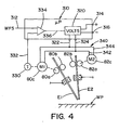
- FIGURES 1 and 2 show an arc welder A using a modified series concept as described in Shutt 4,246,463 incorporated by reference herein.
- the invention involves an electric arc welder schematically illustrated as a submerged arc process.
- the weld performs tandem electric arc welding where first electrode E1 and second electrode E2 are connected in modified series.
- Subsequent electrodes, one of which is illustrated as electrode E3, travel in unison with electrodes E1 and E2 and perform a tandem sub arc welding process.
- more than one trailing electrode E3 is normally used.
- shuttt 4,246,463 is applicable to electric arc welder A used to deposit metal in groove 10 of workpiece WP.
- workpiece WP is spaced plates 12, 14 with a small gap b where edges 20, 22 define trough or groove 24 having an angle 26, best shown in FIGURE 2.
- Electrodes E1, E2 are directed toward a point in groove 24, best shown in FIGURE 2. This point is below the electrical contact sleeve or tip 70, and defines a stickout h.
- mechanism 40 contains electrodes E1, E2 and drives them along groove 10 and includes a main power source 42, with output terminals 44, 46 to direct AC current by way of leads 50, 52 to the respective electrodes E1, E2.
- Wire feeder 80 includes drive rolls 80a, 80b rotated by a motor 80c.
- wire feeder 82 includes drive rolls 82a, 82b rotated by motor 82c.
- Leads 80d and 82d are both powered by a control signal in line 84 from main power source 42.
- the power source is a Power Wave unit manufactured by The Lincoln Electric Company of Cleveland, Ohio and is generally the state table operated welder disclosed in Blankenship 5,278,390. Power source 42 is used to control both wire feeders 80, 82.
- the signal on line 84 must be a compromise signal between the desired wire feed speed of electrodes E1, E2.
- the single signal on line 84 drives both wire feeders. This is an open loop control based upon the desired wire feed speed loaded into the controller of power source 42.
- separate signals for the wire feeder are created when using two power sources, as shown in FIGURE 11.
- Lead 52 is connected to contact tip 72 by line 90 and is connected to workpiece WP by line 92.
- current flow between electrode E1 and power source 42 is through a low resistance line 90 and a higher resistance line 92.
- the resistance of these return paths divides the current flow to adjust the heat in the arc and control penetration by the arc force in the welding process, as described in Shutt 4,246,463.
- By using the two electrode mechanism 40 high metal deposition is obtained by using series connected electrodes E1, E2 while actually using low heat. A limited amount of current flows from electrode E1 into the workpiece during the welding operation.
- This welding process of each power source is controllable in accordance with the preferred embodiment of the present invention, by the program and architecture schematically illustrated in FIGURE 3.
- electrodes E1 and E2 are trailed by at least one electrode E3, shown in FIGURE 2.
- This trailing electrode is moved by single electrode mechanism 100 in unison with two electrode mechanism 40 moving electrodes E1, E2.
- the two mechanisms may be integrated or separately operated.
- the same moving device is used for mechanisms 40, 100.
- the trailing electrode mechanism includes auxiliary power source 102 which is also a Power Wave unit manufactured by The Lincoln Electric Company of Cleveland, Ohio and operated by the technique shown in FIGURE 3.
- Power source 102 has output terminals 104, 106 for directing an AC current waveform by way of lines 110, 112 to employ electrode E3 in a submerged arc welding process.
- Electrode E3 is a wire supplied by spool 114 and is driven through contact tip 120 by wire feeder 130. This feature is similar to wire feeders 80, 82 of electrodes E1, E2.
- Wire feeder 130 has spaced drive rolls 130a, 130b rotated by a motor 130c.
- a control signal from power source 102 in line 132 drives motor 130c to feed electrode E3 toward workpiece WP at a speed determined by the signal in line 132.
- electrodes E1, E2 and trailing electrode E3 create a weld puddle 150 in groove 10.
- Electrodes E1, E2 create a first root pass that joins or tacks edges 20, 22 together by melting the inwardly projecting portions of groove 10.
- Granular flux 152 is deposited in front of electrode E1.
- puddle 150 is formed to displace flux 152 and is covered by bead 154 deposited by electrode E3.
- Flux dispenser 160 is moved in front of electrode E3 and has a dispensing motor 162 for dispensing flux F from hopper 164 through tube 166 in accordance with standard submerged welding technology.
- a similar flux dispenser 160 is then provided above groove 10 in front of electrode E1 to deposit flux 152.
- a shielding gas is employed around electrodes E1, E2.
- the present invention utilizes a Power Wave power source for the main power source 42 and for the auxiliary power source 102 having output terminals 104, 106. These power sources are operated by a digital controller and use a waveform technology process pioneered by The Lincoln Electric Company where the power sources create waveforms defined by a state table. A series of individual current pulses created at a high switching speed in excess of 18 kHz cause a selected waveform to be outputted from the power source. In practice, the waveforms are provided by a series of current pulses created at a rate of over 40 kHz.
- both leading mechanism 40 and following mechanism 100 include a power source that outputs a desired AC waveform to optimize the welding process for the two series electrodes E1, E2, as well as the trailing electrode E3.
- a power source that outputs a desired AC waveform to optimize the welding process for the two series electrodes E1, E2, as well as the trailing electrode E3.
- FIGURE 3 represents the type of power sources used in practicing the preferred embodiments of the present invention and shown in FIGURES 1 and 11.
- System 200 of the present invention is schematically illustrated in FIGURE 3 wherein a Power Wave power source 210 has an input supply 214 and a high switching output stage 212 with output terminals 212a and 212b.
- Output stage 212 creates an AC waveform at output terminals 212a, 212b to perform an AC arc welding process at the weld station illustrated as including electrode 220 and workpiece 222 and having a current shunt 230 to output a signal in line 232.
- This signal represents the current of the welding process being performed.
- Comparator 240 receives the signal on line 232 and has an output 240a with a voltage controlling pulse width modulator circuit 242, which can be digital or analog and has a variety of configurations.
- the pulse width modulator is driven at high speed by oscillator 244 which, in practice, operates at a frequency of about 40 kHz. This frequency of the oscillator drives the pulse width modulator and provides a series of current pulses at a high speed switching rate to create an AC waveform at the weld station.
- the polarity of the waveform is controlled by the logic or signal from network 250 having an input line 252 from waveform generator 260 and an output line 254 for controlling the polarity of the waveform outputted from stage 212 of the Power Wave power source unit.
- the profile of the waveform comprising a series of rapidly created pulses is controlled and dictated by waveform generator 260 having a select network 262 which selects the desired waveform to be created at output terminals 212a, 212b of stage 212.
- the desired waveform is created for use by the electric arc welding mechanisms 40 and 100.
- system 200 includes waveform adjusting circuits 272-278, each having adjusting networks 272a-278a.
- Circuit 272 adjusts the frequency of the waveform.
- a signal from circuit 272 adjusts the frequency of the AC waveform.
- the duty cycle of the waveform is controlled by circuit 272.
- Duty cycle is the time the waveform is in the positive polarity compared to the time in the negative polarity.
- Circuits 276 and 278 control the magnitude of the current during the negative portion of the waveform or the positive portion of the waveform.
- Circuit 276 is to adjust the magnitude of the negative portion of the waveform.
- Circuit 278 adjusts the magnitude of the positive portion of the waveform.
- the waveform used for electrodes E1, E2 is an AC waveform. However, a DC waveform could be used for a trailing electrode E3, although AC current is preferred. Indeed, it is preferred to use an AC waveform for all electrodes of electric arc welder A as shown in FIGURE 10.
- Other circuits have been used to adjust the signal on line 270 to modulate and change the profile of the wave shape selected by network 262 to optimize welding at the intersection of electrodes E1, E2.
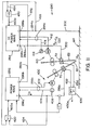
- FIGURE 11 shows tandem electrode welder 290 including a main power source 292 and a second power source 294.
- the main power source 292 has output terminals 296a and 296b. These terminals are connected to leads 292a and 292b, respectively.
- Lead 292a connects the one output of power source 292 to contact tip 70 of electrode E1.
- Lead 292b is connected to line 300 for current flow in a path to and from electrode E2.
- second power source 294 is connected in series between terminal 296b and workpiece WP using lead 294b.
- Second power source 294 has terminals 298a connected to lead 294a and terminal 298b connected to lead 294b. In this manner, second power source 294 is in series with the lead 294b connected to terminal 298b and lead 302.
- electrode E1 carries full current and the current to and from electrode E1 is divided between electrode E2 and the circuit including leads 294b and 302.
- Lead 294a from terminal 298a is connected to lead 292b from power source 292. Consequently, the two power sources 292 and 294 are connected in series between the ground lead 294b and lead 292a. Between the two power sources, line 300 is connected to contact tip 72 of electrode E2. Consequently, electrodes E1 and E2 are in series with a ground current path through Power Wave power source 294.
- the waveforms used for both power source 292 and 294 are the same and are each created by a system 200 as shown in FIGURE 3. Adjustments are made to the waveform process by power source 294 to control the current flowing in the ground path of the welder. Control of power source 294 is accomplished by regulating the current in lead or line 302 flowing to and from workpiece WP. Since two separate power sources are employed, wire feeder 80 is controlled by the signal on line 292c from power source 292. A second wire feeder signal in line 294c is controlled by power source 294.
- Welder 290 has the advantage of being able to control wire feeders 80, 82 separately without complex software in the power source digital control section.
- a main power source could have two parallel modules as illustrated in FIGURE 14, but FIGURE 11 uses series connected modules or power sources. The second power source is connected in series with the ground lead 302 to better control the current waveform in the ground return circuit or path.
- shuttt 4,246,463 are applicable to the series arc connected welder shown in FIGURES 1-3 and shown in FIGURE 11. These welders have two front electrodes connected in series and have a current return path through the workpiece. The front welders are combined with trailing welders to perform a tandem submerged arc weld.
- the wire feeders are controlled by a single section 310 in the digital controller of power source 42.
- Controller section 310 receives a wire feed speed signal on line 312 and converts the DC voltage on terminals 314, 316 into a DC output signal from voltage signal generator 320 on output lines 322, 324.
- the signal on line 312 is often adjusted to maintain a given arc length.
- the same DC voltage on lines 322, 324 is supplied to both motor 80c and motor 82c to drive electrode E1 and electrode E2 in unison toward the intersecting point, where a series arc is created to melt the electrodes and fill the gap in groove 10 of workpiece WP.
- motor 80c has an output tachometer 330 creating,a voltage on line 332. This voltage represents the speed of motor M1 driving leading electrode or wire E1 toward workpiece WP.
- First motor M1 is controlled by a feedback loop including error amplifier 334 generating an output error signal in line 336 determined by the relationship of the actual feed speed represented by the voltage on line 332 and the set or adjusted desired feed speed as represented by the voltage or digital signal on line 312. Consequently, motor M1 has a tachometer that generates a feedback WFS signal so the section 310 creates a control WFS signal across output lines 322, 324. First motor M1 is maintained at the set or adjusted wire feed speed represented by the voltage or digital signal on line 312.
- a slave circuit 340 is preferably formed as leads 342, 344 to drive motor 82c. In this implementation of the present invention, motor M1 and motor M2 are driven in unison by the same AC voltage.
- Slave circuit 340 is merely an extension of output lines 322, 324, so the voltage on both motor M1 and motor M2 are the same.
- the two motors are driven at the same speed and the lead motor M1 is regulated by a feedback loop.
- one of the wire feeders is driven at optimum, desired speed. This speed is controlled.
- the other motor merely follows at a related speed.
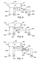
- This novel feature is modified slightly as shown in FIGURES 5-7.
- the slave circuit is rheostat 340a so that the voltage on leads 342, 344 is adjusted to a lower level than the voltage on lines 322, 324. Consequently, motor M2 is adjusted to operate at a slightly slower speed than motor M1.
- motor M1 can be adjusted by rheostat 360 to operate at slightly lower speed than motor M2, as illustrated in the version shown in FIGURE 6.
- Rheostat 360 is connected between lines 322, 324 and motor M1.
- Slave circuit 340 is the same as used in the version shown in FIGURE 4.
- motor M1 is driven at a fixed feedback control speed but the motor M2 is driven at a higher speed.
- the second motor is still driven as a slave; however, this slave driven motor can be operated at a speed below or a speed above the feedback speed of motor M1.
- FIGURE 7 A further version of this concept is illustrated in FIGURE 7 wherein the slave circuit is boost converter 370 having an output controlled by rheostat 372.
- the voltage on leads 342, 344 is greater than the voltage on lines 322, 324.
- Motor M2 is driven at a speed higher than motor M1.
- a buck converter could be used for the slave circuit so that the voltage driving motor M2 is less than the voltage driving motor M1.
- leading electrode E1 has a feedback loop controlled wire feed speed and trailing electrode E2 is driven at a speed in a fixed relationship to the speed of motor M1.
- One of the motors is optimized, while the other motor has a correlated wire feed speed.
- each of the motors M1, M2 could have a gear reducer with a different gear ratio.
- the invention is a version used with a single power source welder as shown in FIGURES 1-4.
- the second embodiment of the present invention is illustrated in FIGURE 11 wherein a single power source is replaced by two power sources 292, 294 connected in series and already generally described.
- the concept of FIGURE 4 used for the single power source welder is also applicable to the two power source welder of FIGURE 11.
- the welder in FIGURE 11 is provided with a first wire feeder 400 for driving electrode or wire E1 toward workpiece WP by motor M1.
- the first motor is controlled by signals through lead 292c connected to first power source 292 and shown as a coaxial cable.
- One of these signals is a voltage on line 402, which is a DC signal actually using two lines for directing a DC voltage signal to motor M1.
- Motor M1 has tachometer 406 to generate a voltage on line 404 which is the feedback signal used to control the wire feed speed and, thus, the DC voltage signal on line 402.
- second wire feeder 410 is driven by motor M2 through lead 294c which is actually a coaxial cable connected to the controller of second power source 294.
- Coaxial line or cable 294c includes a line 412 having a DC voltage for driving motor M2 at a speed determined by the level of the DC voltage.
- Tachometer 416 creates a voltage in line 414 forming the feedback signal to control the wire feed speed of feeder 410.
- power source 292 controls motor M1 of feeder 410 with a feedback loop.
- a feedback loop or circuit is also used to control the speed of feeder 410.
- Two power sources are used for the series arc welding by electrodes E1, E2.
- Each of the wire feeders is separately controlled by one of two power sources 292, 294.
- a voltage is sensed by circuit or device 420 connected to the workpiece lead 302 by line 422 and to contact tip 70 by line 424.
- Circuit or device 420 provides a voltage on line 420a which adjusts the desired wire feed speed to be controlled by the signals through lead 292c.
- Option circuit or device 440 has an output voltage on line 430a controlled by voltage between contact tips 70, 72 using lines 432, 434.
- voltage sensing circuit or device 450 has an output 450a with a voltage signal indicative of the voltage between contact tip 72 as read by line 452 and workpiece WP as read by line 454 from lead 302 through line 422.
- the signal on output line 450a adjusts the wire feed speed of feeder 410 and the signal on line 420a adjusts the wire feed speed of feeder 400.
- the wire feeders 400, 410 can be separately adjusted to optimize the operation of the series welder shown in FIGURE 11.
- Power sources 292, 294 are connected in series and are moved in unison along workpiece WP.
- the welding operation is a modified series arc process, even though the invention could be used in a series arc welding process.
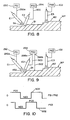
- FIGURE 11 The technical distinction between series arc and modified series arc using the novel concept of two power sources as shown in FIGURE 11 is schematically represented in FIGURES 8 and 9.
- the power supplies 292, 294 are connected in series across electrodes E1, E2. This connection creates a series arc SA to melt electrodes E1, E2 for forming molten metal bead B1. Trailing electrode E3 receives a waveform from power source 102 to form a subsequent molten metal bead B2.
- the welder shown in FIGURE 11 can be used for series arc welding as schematically illustrated in FIGURE 8.
- terminal 298b between power source 294 and workpiece WP by line 300, a modified series arc welding process is implemented, as shown in FIGURE 9.
- Modified series arc MSA is created between electrode E1 and electrode E2 and is also directed to workpiece WP, as described in Shutt 4,246,463.
- the welder shown in FIGURE 11 can be connected in a series arc configuration of FIGURE 8 or the modified series arc configuration of FIGURE 9.
- waveform generator 260 associated with each power source creates a waveform 500 so that the same waveform is outputted from the two power sources.
- Waveform 500 for both power sources is created in unison, as shown in FIGURE 10; however, the actual current is 180° out of phase in electrodes E1, E2.
- the power source for tandem electrode E3 is AC waveform 502 which is out of phase with waveform 500 of the two power sources.
- the phase shift is preferably 90° as shown in FIGURE 10.
- the waveforms from the first and second power sources are AC waveforms in phase and the waveform for tandem electrode E3 is an AC waveform which is out of phase.
- the digital circuits of the power sources used in the welder shown in FIGURE 11 utilizes the voltages on lines 420a and 450a, as schematically illustrated in FIGURE 11A.
- the digital circuits are shown in analog components.
- the instantaneous voltage from voltage circuit or device 420 on lines 420a is averaged by digital circuit 510 to produce average V1 voltage on line 512.
- This average voltage is compared with a set voltage on line 514 by error amplifier 516 to create an error signal on line 518.
- This signal is used to adjust the wire feed speed of feeder 400.
- the voltage signal on output line 450a is averaged by circuit 520 to produce an average V2 voltage signal on line 522.
- FIGURES 11 and 11A illustrate the separate control of the two wire feed speeds when using two separate power sources for the series arc welder of FIGURE 8 or modified series arc welder of FIGURE 9.
- the current from the electrodes to the workpiece is ground current I G .
- Most inverter type power sources have a standard program for clearing a short between the electrode and workpiece. When there is a short circuit, the ground current I g increases drastically. To clear the short, the current of the power source is ramped up to burn away the short circuit. When doing this in an architecture involving a modified series arc, as the ground current increases, the current on electrode E2 drastically decreases since power source 294 regulates current in lead 302. This reaction to a short reduces the melting of the second electrode and has a tendency to cause the electrode to be projected against the workpiece. As the current of power source 294 increases, current I g in the arc decreases. This has created instability.
- this situation involved in a modified series arc welder is rectified or reduced in importance by a circuit which detects the short and then controls the current in electrode E2 with a program that actually controls the current of power source 294 for the purpose of maintaining melting of electrode E2. Furthermore, when electrode E2 is grounded, V2 decreases drastically which affects the wire feed speed control set forth in FIGURE 11A. To rectify this current deficiency and correct the speed of the electrode advancing toward the workpiece, a program is employed such as shown in FIGURE 12 wherein the voltage across contact or tip 72 and workpiece WP is directed to a standard short detect circuit 600.
- V2 When there is a short, V2 is reduced and a logic appears on line 602 to activate digital control program 604, which program is a routine that attempts to maintain the current in power source 294 at a given level to effect clearing of the short circuit and decrease the wire feed speed of feeder 410.
- FIGURE 13 an alternate technique is illustrated in FIGURE 13 wherein short detector circuit 610 produces a short signal on line 612 to activate digital program 614. This program decreases current of power source 294. This creates the tendency to decrease the ground current and increase the current in electrode E2.
- the two circuits shown in FIGURES 12 and 13 are representative in nature and are used to perform an aspect of the invention, wherein a short circuit is detected so constant current power source 294 is controlled to burn away the short circuit and control movement of electrode E2 toward the workpiece. Other programs can be used to control the actual current in electrode E2 or the current created by the second power source.
- the invention involves the use of two power sources for use in a modified series arc welding process.
- the two power sources are connected in series, as shown in FIGURE 11; however, they may be connected in parallel as schematically illustrated in FIGURE 14.
- Terminal 296a of power source 292 is connected to terminal 298a of power source 294.
- terminal 296b is connected to terminal 298b.
- To drive contact tip 72 terminal 298b is connected by low resistance lead 620 and the workpiece is connected by lead 622.
- the wire feed speed of feeder 400 is controlled by a WFS signal on line 294c from second power source 294.
- the first power source 292 controls the speed of feeder 410 by a signal on line 292c. Both of these signals are created by a feedback technique already described.
- the various voltages for feedback control of the wire feed speed are within the skill of the art and need not be shown.
Landscapes
- Engineering & Computer Science (AREA)
- Physics & Mathematics (AREA)
- Plasma & Fusion (AREA)
- Mechanical Engineering (AREA)
- Arc Welding In General (AREA)
- Arc Welding Control (AREA)
Applications Claiming Priority (1)
| Application Number | Priority Date | Filing Date | Title |
|---|---|---|---|
| US11/327,736 US9579742B2 (en) | 2006-01-09 | 2006-01-09 | Series arc welder |
Publications (3)
| Publication Number | Publication Date |
|---|---|
| EP1864746A2 true EP1864746A2 (fr) | 2007-12-12 |
| EP1864746A3 EP1864746A3 (fr) | 2007-12-19 |
| EP1864746B1 EP1864746B1 (fr) | 2011-10-05 |
Family
ID=38231762
Family Applications (1)
| Application Number | Title | Priority Date | Filing Date |
|---|---|---|---|
| EP06017853A Active EP1864746B1 (fr) | 2006-01-09 | 2006-08-26 | Appareil pour soudure à arc en série amélioré avec dispositifs de contrôle de la vitesse de fil |
Country Status (3)
| Country | Link |
|---|---|
| US (1) | US9579742B2 (fr) |
| EP (1) | EP1864746B1 (fr) |
| AT (1) | ATE527078T1 (fr) |
Cited By (1)
| Publication number | Priority date | Publication date | Assignee | Title |
|---|---|---|---|---|
| CN102528224A (zh) * | 2011-12-19 | 2012-07-04 | 湖南科技大学 | 用于双丝焊的交直流电流与电压信号检测装置 |
Families Citing this family (45)
| Publication number | Priority date | Publication date | Assignee | Title |
|---|---|---|---|---|
| FR2926236B1 (fr) * | 2008-01-10 | 2010-08-27 | Air Liquide | Installation de soudage a l'arc submerge a plusieurs tetes de soudage et procede de soudage de tube associe. |
| WO2010046937A1 (fr) * | 2008-10-21 | 2010-04-29 | Me-Ca S.R.L. | Procédé de soudage bout à bout de plaques en tôle, et machine à souder destinée à l’application de ce procédé |
| US9839970B2 (en) | 2010-12-21 | 2017-12-12 | Lincoln Global, Inc. | Dual wire welding system and method |
| JP5706709B2 (ja) * | 2011-02-16 | 2015-04-22 | 株式会社ダイヘン | 2ワイヤ溶接制御方法 |
| JP5706710B2 (ja) * | 2011-02-18 | 2015-04-22 | 株式会社ダイヘン | 2ワイヤ溶接制御方法 |
| WO2013008394A1 (fr) * | 2011-07-12 | 2013-01-17 | パナソニック株式会社 | Procédé de commande de soudage à l'arc et dispositif de soudage à l'arc |
| CN103958108B (zh) * | 2011-11-29 | 2017-10-13 | 杰富意钢铁株式会社 | 钢板的埋弧焊方法 |
| US9283635B2 (en) * | 2012-03-02 | 2016-03-15 | Lincoln Global, Inc. | Synchronized hybrid gas metal arc welding with TIG/plasma welding |
| US9862050B2 (en) | 2012-04-03 | 2018-01-09 | Lincoln Global, Inc. | Auto steering in a weld joint |
| US10239145B2 (en) | 2012-04-03 | 2019-03-26 | Lincoln Global, Inc. | Synchronized magnetic arc steering and welding |
| US9878393B2 (en) | 2012-06-08 | 2018-01-30 | Illinois Tool Works Inc. | Welding wire feeder power control system and method |
| US10384289B2 (en) | 2012-06-08 | 2019-08-20 | Illinois Tool Works Inc. | Welding wire feeder bus control system and method |
| US10406621B2 (en) | 2012-06-08 | 2019-09-10 | Illinois Tool Works Inc. | Polarity sensing welding wire feeder system and method |
| US9463523B2 (en) | 2012-06-08 | 2016-10-11 | Illinois Tool Works Inc. | Controlled waveform welding wire feeder system and method |
| US9662735B2 (en) | 2012-06-08 | 2017-05-30 | Illinois Tool Works Inc. | Welding wire feeder power application system and method |
| US10105781B2 (en) | 2012-06-08 | 2018-10-23 | Illinois Tool Works Inc. | Welding system inrush current control system and method |
| KR101954485B1 (ko) * | 2012-08-14 | 2019-05-22 | 이에스에이비 아베 | 서브머지드 아크 용접을 위한 방법 및 시스템 |
| EP2914398B1 (fr) * | 2012-11-02 | 2017-01-04 | Esab AB | Procédé de démarrage d'un processus de soudage à l'arc submergé et appareil de soudage |
| US10035211B2 (en) * | 2013-03-15 | 2018-07-31 | Lincoln Global, Inc. | Tandem hot-wire systems |
| US10086465B2 (en) | 2013-03-15 | 2018-10-02 | Lincoln Global, Inc. | Tandem hot-wire systems |
| US10464168B2 (en) | 2014-01-24 | 2019-11-05 | Lincoln Global, Inc. | Method and system for additive manufacturing using high energy source and hot-wire |
| US10343231B2 (en) * | 2014-05-28 | 2019-07-09 | Awds Technologies Srl | Wire feeding system |
| EP2978097A1 (fr) * | 2014-07-23 | 2016-01-27 | Siemens Aktiengesellschaft | Alimentation d'électrodes fusibles au moyen d'un convertisseur |
| US10010962B1 (en) | 2014-09-09 | 2018-07-03 | Awds Technologies Srl | Module and system for controlling and recording welding data, and welding wire feeder |
| US10350696B2 (en) | 2015-04-06 | 2019-07-16 | Awds Technologies Srl | Wire feed system and method of controlling feed of welding wire |
| US11491573B2 (en) | 2015-08-17 | 2022-11-08 | Illinois Tool Works Inc. | Portable advanced process module |
| US9975728B2 (en) | 2015-09-10 | 2018-05-22 | Sidergas Spa | Wire container lid, wire container and wire feeding system |
| EP3366404B1 (fr) * | 2015-10-23 | 2020-09-16 | Panasonic Intellectual Property Management Co., Ltd. | Chalumeau soudeur |
| EP3702084A1 (fr) | 2016-03-11 | 2020-09-02 | Daihen Corporation | Système de soudage à l'arc et dispositif d'alimentation en fil |
| US10688589B2 (en) | 2017-06-20 | 2020-06-23 | Esab Ab | System and method for monitoring resistance in a wire feed device |
| US10792752B2 (en) | 2017-08-08 | 2020-10-06 | Lincoln Global, Inc. | Dual wire welding or additive manufacturing system and method |
| US10532418B2 (en) | 2017-08-08 | 2020-01-14 | Lincoln Global, Inc. | Dual wire welding or additive manufacturing contact tip and diffuser |
| US11440121B2 (en) | 2017-08-08 | 2022-09-13 | Lincoln Global, Inc. | Dual wire welding or additive manufacturing system and method |
| US11504788B2 (en) * | 2017-08-08 | 2022-11-22 | Lincoln Global, Inc. | Dual wire welding or additive manufacturing system and method |
| US11027362B2 (en) | 2017-12-19 | 2021-06-08 | Lincoln Global, Inc. | Systems and methods providing location feedback for additive manufacturing |
| EP3626381A1 (fr) * | 2018-09-20 | 2020-03-25 | FRONIUS INTERNATIONAL GmbH | Procédé de fabrication de structures métalliques |
| US11285557B2 (en) | 2019-02-05 | 2022-03-29 | Lincoln Global, Inc. | Dual wire welding or additive manufacturing system |
| CN110091035A (zh) * | 2019-06-03 | 2019-08-06 | 河北科技大学 | 一种高熵合金增材制造装置及增材制造方法 |
| CN110465722A (zh) * | 2019-08-29 | 2019-11-19 | 广船国际有限公司 | 一种通过fcb焊焊接y型坡口板材的方法 |
| US11498146B2 (en) | 2019-09-27 | 2022-11-15 | Lincoln Global, Inc. | Dual wire welding or additive manufacturing system and method |
| US11174121B2 (en) | 2020-01-20 | 2021-11-16 | Awds Technologies Srl | Device for imparting a torsional force onto a wire |
| US11278981B2 (en) | 2020-01-20 | 2022-03-22 | Awds Technologies Srl | Device for imparting a torsional force onto a wire |
| US12076823B2 (en) | 2021-03-01 | 2024-09-03 | Esab Ab | Braking energy recovery circuit |
| US12168268B2 (en) | 2021-05-20 | 2024-12-17 | Lincoln Global, Inc. | Reduction of droplet size for CO2 shielded welding wire |
| JP2025129623A (ja) * | 2024-02-26 | 2025-09-05 | 株式会社ダイヘン | サブマージアーク溶接制御方法 |
Citations (3)
| Publication number | Priority date | Publication date | Assignee | Title |
|---|---|---|---|---|
| GB1502288A (en) | 1974-02-25 | 1978-03-01 | Akad Tekn Videnskaber | Method and an apparatus for automatic electric welding |
| US4301355A (en) | 1980-08-04 | 1981-11-17 | Dimetrics, Inc. | Gas metal arc welding system |
| US5973291A (en) | 1998-08-11 | 1999-10-26 | Lincoln Global, Inc. | Method and system for determining the feedability of welding wire |
Family Cites Families (19)
| Publication number | Priority date | Publication date | Assignee | Title |
|---|---|---|---|---|
| US2669640A (en) | 1950-05-22 | 1954-02-16 | Union Carbide & Carbon Corp | Submerged-melt electric series-arc welding |
| US2629640A (en) * | 1950-07-08 | 1953-02-24 | Hydropress Inc | Bearing |
| US2938107A (en) * | 1958-01-13 | 1960-05-24 | Smith Corp A O | Series arc welding circuit |
| US3562612A (en) * | 1968-10-21 | 1971-02-09 | Westinghouse Electric Corp | Thyristor powered reversible dual motor drive with voltage and current feedback |
| JPS5113347A (ja) * | 1974-07-25 | 1976-02-02 | Osaka Transformer Co Ltd | Shomodenkyokushikiaakuyosetsuki |
| US4246463A (en) * | 1979-02-13 | 1981-01-20 | The Lincoln Electric Company | Method and apparatus for arc welding of metal plates from one side only |
| JPS564381A (en) | 1979-06-22 | 1981-01-17 | Mitsubishi Heavy Ind Ltd | Two electrode submerged arc welding method |
| IT1179830B (it) * | 1984-11-26 | 1987-09-16 | Fiat Auto Spa | Dispositivo di controllo per apparecchiature per saldatura elettrica a resistenza particolarmente per il controllo di apparecchiature per la saldatura di parti di carrozzerie di autoveicoli |
| CH678825A5 (fr) * | 1986-06-03 | 1991-11-15 | Mitsubishi Electric Corp | |
| SU1540996A1 (ru) * | 1987-11-09 | 1990-02-07 | Научно-Производственное Объединение По Выпуску Механического Сварочного Оборудования "Висп" | Роликовый вращатель |
| DE4112760A1 (de) * | 1991-04-19 | 1992-10-22 | Planeta Druckmaschinenwerk Ag | Mehrfachantrieb an druckmaschinen |
| US6207929B1 (en) * | 1999-06-21 | 2001-03-27 | Lincoln Global, Inc. | Tandem electrode welder and method of welding with two electrodes |
| US6291798B1 (en) * | 1999-09-27 | 2001-09-18 | Lincoln Global, Inc. | Electric ARC welder with a plurality of power supplies |
| US6717107B1 (en) * | 2001-05-29 | 2004-04-06 | Lincoln Global, Inc. | Two stage welder and method of operating same |
| US6717108B2 (en) * | 2001-10-12 | 2004-04-06 | Lincoln Global, Inc. | Electric arc welder and method of designing waveforms therefor |
| US7041937B2 (en) * | 2003-06-04 | 2006-05-09 | Illinois Tool Works Inc. | Wire feeder operable with lower minimum input voltage requirement |
| US7105773B2 (en) | 2004-01-12 | 2006-09-12 | Lincoln Global, Inc. | Electric arc welder |
| US7183516B2 (en) * | 2004-05-24 | 2007-02-27 | Lincoln Global, Inc. | System and method for welding with multiple arcs |
| US7301124B2 (en) * | 2005-01-26 | 2007-11-27 | Illinois Tool Works Inc. | System and method for coordinating wire feeder motor operation |
-
2006
- 2006-01-09 US US11/327,736 patent/US9579742B2/en active Active
- 2006-08-26 AT AT06017853T patent/ATE527078T1/de active
- 2006-08-26 EP EP06017853A patent/EP1864746B1/fr active Active
Patent Citations (3)
| Publication number | Priority date | Publication date | Assignee | Title |
|---|---|---|---|---|
| GB1502288A (en) | 1974-02-25 | 1978-03-01 | Akad Tekn Videnskaber | Method and an apparatus for automatic electric welding |
| US4301355A (en) | 1980-08-04 | 1981-11-17 | Dimetrics, Inc. | Gas metal arc welding system |
| US5973291A (en) | 1998-08-11 | 1999-10-26 | Lincoln Global, Inc. | Method and system for determining the feedability of welding wire |
Cited By (1)
| Publication number | Priority date | Publication date | Assignee | Title |
|---|---|---|---|---|
| CN102528224A (zh) * | 2011-12-19 | 2012-07-04 | 湖南科技大学 | 用于双丝焊的交直流电流与电压信号检测装置 |
Also Published As
| Publication number | Publication date |
|---|---|
| US20070158324A1 (en) | 2007-07-12 |
| US9579742B2 (en) | 2017-02-28 |
| EP1864746B1 (fr) | 2011-10-05 |
| ATE527078T1 (de) | 2011-10-15 |
| EP1864746A3 (fr) | 2007-12-19 |
Similar Documents
| Publication | Publication Date | Title |
|---|---|---|
| EP1864746B1 (fr) | Appareil pour soudure à arc en série amélioré avec dispositifs de contrôle de la vitesse de fil | |
| EP2720821B1 (fr) | Soudage à l'arc en série modifié et commande améliorée d'un soudage à l'arc en série à un côté | |
| US11638966B2 (en) | Short arc welding system | |
| US9987701B2 (en) | Hybrid pulsed-short circuit welding regime | |
| US8203100B2 (en) | Pulse arc welding method | |
| US8519302B2 (en) | Electric arc welder | |
| US20160288235A1 (en) | Controlled short circuit welding system and method | |
| US10195681B2 (en) | Short arc welding system | |
| US20150343549A1 (en) | Multiple electrode welding system with reduced spatter | |
| EP4180163A1 (fr) | Système de soudage ou de fabrication additive avec alimentation d'électrode discontinue | |
| CA3068228C (fr) | Systemes et methodes pour un ajustement controle de temps de phase d'arc et de court-circuit | |
| US11285559B2 (en) | Welding system and method for shielded welding wires | |
| US12427596B2 (en) | Hybrid projected and streaming pulse welding | |
| WO2014140745A1 (fr) | Systèmes à fil chaud en tandem | |
| JP2025063579A (ja) | 非消耗電極アーク溶接方法 | |
| JP2025101209A (ja) | サブマージアーク溶接システム、および、サブマージアーク溶接方法 |
Legal Events
| Date | Code | Title | Description |
|---|---|---|---|
| PUAI | Public reference made under article 153(3) epc to a published international application that has entered the european phase |
Free format text: ORIGINAL CODE: 0009012 |
|
| PUAL | Search report despatched |
Free format text: ORIGINAL CODE: 0009013 |
|
| AK | Designated contracting states |
Kind code of ref document: A2 Designated state(s): AT BE BG CH CY CZ DE DK EE ES FI FR GB GR HU IE IS IT LI LT LU LV MC NL PL PT RO SE SI SK TR |
|
| AX | Request for extension of the european patent |
Extension state: AL BA HR MK YU |
|
| AK | Designated contracting states |
Kind code of ref document: A3 Designated state(s): AT BE BG CH CY CZ DE DK EE ES FI FR GB GR HU IE IS IT LI LT LU LV MC NL PL PT RO SE SI SK TR |
|
| AX | Request for extension of the european patent |
Extension state: AL BA HR MK YU |
|
| 17P | Request for examination filed |
Effective date: 20080619 |
|
| 17Q | First examination report despatched |
Effective date: 20080728 |
|
| AKX | Designation fees paid |
Designated state(s): AT BE BG CH CY CZ DE DK EE ES FI FR GB GR HU IE IS IT LI LT LU LV MC NL PL PT RO SE SI SK TR |
|
| AXX | Extension fees paid |
Extension state: RS Payment date: 20080619 Extension state: MK Payment date: 20080619 Extension state: HR Payment date: 20080619 Extension state: AL Payment date: 20080619 Extension state: BA Payment date: 20080619 |
|
| GRAP | Despatch of communication of intention to grant a patent |
Free format text: ORIGINAL CODE: EPIDOSNIGR1 |
|
| GRAS | Grant fee paid |
Free format text: ORIGINAL CODE: EPIDOSNIGR3 |
|
| GRAA | (expected) grant |
Free format text: ORIGINAL CODE: 0009210 |
|
| AK | Designated contracting states |
Kind code of ref document: B1 Designated state(s): AT BE BG CH CY CZ DE DK EE ES FI FR GB GR HU IE IS IT LI LT LU LV MC NL PL PT RO SE SI SK TR |
|
| AX | Request for extension of the european patent |
Extension state: AL BA HR MK RS |
|
| REG | Reference to a national code |
Ref country code: GB Ref legal event code: FG4D |
|
| REG | Reference to a national code |
Ref country code: DE Ref legal event code: R081 Ref document number: 602006024802 Country of ref document: DE Owner name: LINCOLN GLOBAL, INC., SANTA FE SPRINGS, US Free format text: FORMER OWNER: LINCOLN GLOBAL, INC., CITY OF INDUSTRY, CALIF., US |
|
| REG | Reference to a national code |
Ref country code: CH Ref legal event code: EP |
|
| REG | Reference to a national code |
Ref country code: IE Ref legal event code: FG4D |
|
| REG | Reference to a national code |
Ref country code: DE Ref legal event code: R096 Ref document number: 602006024802 Country of ref document: DE Effective date: 20111201 |
|
| REG | Reference to a national code |
Ref country code: SE Ref legal event code: TRGR |
|
| REG | Reference to a national code |
Ref country code: NL Ref legal event code: VDEP Effective date: 20111005 |
|
| PG25 | Lapsed in a contracting state [announced via postgrant information from national office to epo] |
Ref country code: SI Free format text: LAPSE BECAUSE OF FAILURE TO SUBMIT A TRANSLATION OF THE DESCRIPTION OR TO PAY THE FEE WITHIN THE PRESCRIBED TIME-LIMIT Effective date: 20111005 |
|
| LTIE | Lt: invalidation of european patent or patent extension |
Effective date: 20111005 |
|
| PG25 | Lapsed in a contracting state [announced via postgrant information from national office to epo] |
Ref country code: LT Free format text: LAPSE BECAUSE OF FAILURE TO SUBMIT A TRANSLATION OF THE DESCRIPTION OR TO PAY THE FEE WITHIN THE PRESCRIBED TIME-LIMIT Effective date: 20111005 Ref country code: BE Free format text: LAPSE BECAUSE OF FAILURE TO SUBMIT A TRANSLATION OF THE DESCRIPTION OR TO PAY THE FEE WITHIN THE PRESCRIBED TIME-LIMIT Effective date: 20111005 Ref country code: IS Free format text: LAPSE BECAUSE OF FAILURE TO SUBMIT A TRANSLATION OF THE DESCRIPTION OR TO PAY THE FEE WITHIN THE PRESCRIBED TIME-LIMIT Effective date: 20120205 |
|
| PG25 | Lapsed in a contracting state [announced via postgrant information from national office to epo] |
Ref country code: NL Free format text: LAPSE BECAUSE OF FAILURE TO SUBMIT A TRANSLATION OF THE DESCRIPTION OR TO PAY THE FEE WITHIN THE PRESCRIBED TIME-LIMIT Effective date: 20111005 Ref country code: PT Free format text: LAPSE BECAUSE OF FAILURE TO SUBMIT A TRANSLATION OF THE DESCRIPTION OR TO PAY THE FEE WITHIN THE PRESCRIBED TIME-LIMIT Effective date: 20120206 Ref country code: GR Free format text: LAPSE BECAUSE OF FAILURE TO SUBMIT A TRANSLATION OF THE DESCRIPTION OR TO PAY THE FEE WITHIN THE PRESCRIBED TIME-LIMIT Effective date: 20120106 Ref country code: LV Free format text: LAPSE BECAUSE OF FAILURE TO SUBMIT A TRANSLATION OF THE DESCRIPTION OR TO PAY THE FEE WITHIN THE PRESCRIBED TIME-LIMIT Effective date: 20111005 |
|
| PG25 | Lapsed in a contracting state [announced via postgrant information from national office to epo] |
Ref country code: CY Free format text: LAPSE BECAUSE OF FAILURE TO SUBMIT A TRANSLATION OF THE DESCRIPTION OR TO PAY THE FEE WITHIN THE PRESCRIBED TIME-LIMIT Effective date: 20111005 |
|
| PG25 | Lapsed in a contracting state [announced via postgrant information from national office to epo] |
Ref country code: CZ Free format text: LAPSE BECAUSE OF FAILURE TO SUBMIT A TRANSLATION OF THE DESCRIPTION OR TO PAY THE FEE WITHIN THE PRESCRIBED TIME-LIMIT Effective date: 20111005 Ref country code: EE Free format text: LAPSE BECAUSE OF FAILURE TO SUBMIT A TRANSLATION OF THE DESCRIPTION OR TO PAY THE FEE WITHIN THE PRESCRIBED TIME-LIMIT Effective date: 20111005 Ref country code: DK Free format text: LAPSE BECAUSE OF FAILURE TO SUBMIT A TRANSLATION OF THE DESCRIPTION OR TO PAY THE FEE WITHIN THE PRESCRIBED TIME-LIMIT Effective date: 20111005 Ref country code: SK Free format text: LAPSE BECAUSE OF FAILURE TO SUBMIT A TRANSLATION OF THE DESCRIPTION OR TO PAY THE FEE WITHIN THE PRESCRIBED TIME-LIMIT Effective date: 20111005 Ref country code: BG Free format text: LAPSE BECAUSE OF FAILURE TO SUBMIT A TRANSLATION OF THE DESCRIPTION OR TO PAY THE FEE WITHIN THE PRESCRIBED TIME-LIMIT Effective date: 20120105 |
|
| PLBE | No opposition filed within time limit |
Free format text: ORIGINAL CODE: 0009261 |
|
| STAA | Information on the status of an ep patent application or granted ep patent |
Free format text: STATUS: NO OPPOSITION FILED WITHIN TIME LIMIT |
|
| PG25 | Lapsed in a contracting state [announced via postgrant information from national office to epo] |
Ref country code: RO Free format text: LAPSE BECAUSE OF FAILURE TO SUBMIT A TRANSLATION OF THE DESCRIPTION OR TO PAY THE FEE WITHIN THE PRESCRIBED TIME-LIMIT Effective date: 20111005 Ref country code: PL Free format text: LAPSE BECAUSE OF FAILURE TO SUBMIT A TRANSLATION OF THE DESCRIPTION OR TO PAY THE FEE WITHIN THE PRESCRIBED TIME-LIMIT Effective date: 20111005 |
|
| 26N | No opposition filed |
Effective date: 20120706 |
|
| REG | Reference to a national code |
Ref country code: DE Ref legal event code: R097 Ref document number: 602006024802 Country of ref document: DE Effective date: 20120706 |
|
| REG | Reference to a national code |
Ref country code: CH Ref legal event code: PL |
|
| PG25 | Lapsed in a contracting state [announced via postgrant information from national office to epo] |
Ref country code: MC Free format text: LAPSE BECAUSE OF NON-PAYMENT OF DUE FEES Effective date: 20120831 |
|
| GBPC | Gb: european patent ceased through non-payment of renewal fee |
Effective date: 20120826 |
|
| PG25 | Lapsed in a contracting state [announced via postgrant information from national office to epo] |
Ref country code: CH Free format text: LAPSE BECAUSE OF NON-PAYMENT OF DUE FEES Effective date: 20120831 Ref country code: LI Free format text: LAPSE BECAUSE OF NON-PAYMENT OF DUE FEES Effective date: 20120831 Ref country code: ES Free format text: LAPSE BECAUSE OF FAILURE TO SUBMIT A TRANSLATION OF THE DESCRIPTION OR TO PAY THE FEE WITHIN THE PRESCRIBED TIME-LIMIT Effective date: 20120116 |
|
| REG | Reference to a national code |
Ref country code: FR Ref legal event code: ST Effective date: 20130430 |
|
| REG | Reference to a national code |
Ref country code: IE Ref legal event code: MM4A |
|
| PG25 | Lapsed in a contracting state [announced via postgrant information from national office to epo] |
Ref country code: FI Free format text: LAPSE BECAUSE OF FAILURE TO SUBMIT A TRANSLATION OF THE DESCRIPTION OR TO PAY THE FEE WITHIN THE PRESCRIBED TIME-LIMIT Effective date: 20111005 |
|
| PG25 | Lapsed in a contracting state [announced via postgrant information from national office to epo] |
Ref country code: GB Free format text: LAPSE BECAUSE OF NON-PAYMENT OF DUE FEES Effective date: 20120826 Ref country code: IE Free format text: LAPSE BECAUSE OF NON-PAYMENT OF DUE FEES Effective date: 20120826 |
|
| PG25 | Lapsed in a contracting state [announced via postgrant information from national office to epo] |
Ref country code: FR Free format text: LAPSE BECAUSE OF NON-PAYMENT OF DUE FEES Effective date: 20120831 |
|
| PGFP | Annual fee paid to national office [announced via postgrant information from national office to epo] |
Ref country code: AT Payment date: 20130801 Year of fee payment: 8 Ref country code: SE Payment date: 20130828 Year of fee payment: 8 |
|
| PGFP | Annual fee paid to national office [announced via postgrant information from national office to epo] |
Ref country code: IT Payment date: 20130822 Year of fee payment: 8 |
|
| PG25 | Lapsed in a contracting state [announced via postgrant information from national office to epo] |
Ref country code: TR Free format text: LAPSE BECAUSE OF FAILURE TO SUBMIT A TRANSLATION OF THE DESCRIPTION OR TO PAY THE FEE WITHIN THE PRESCRIBED TIME-LIMIT Effective date: 20111005 |
|
| PG25 | Lapsed in a contracting state [announced via postgrant information from national office to epo] |
Ref country code: LU Free format text: LAPSE BECAUSE OF NON-PAYMENT OF DUE FEES Effective date: 20120826 |
|
| PG25 | Lapsed in a contracting state [announced via postgrant information from national office to epo] |
Ref country code: HU Free format text: LAPSE BECAUSE OF FAILURE TO SUBMIT A TRANSLATION OF THE DESCRIPTION OR TO PAY THE FEE WITHIN THE PRESCRIBED TIME-LIMIT Effective date: 20060826 |
|
| REG | Reference to a national code |
Ref country code: SE Ref legal event code: EUG |
|
| REG | Reference to a national code |
Ref country code: AT Ref legal event code: MM01 Ref document number: 527078 Country of ref document: AT Kind code of ref document: T Effective date: 20140826 |
|
| PG25 | Lapsed in a contracting state [announced via postgrant information from national office to epo] |
Ref country code: IT Free format text: LAPSE BECAUSE OF NON-PAYMENT OF DUE FEES Effective date: 20140826 |
|
| PG25 | Lapsed in a contracting state [announced via postgrant information from national office to epo] |
Ref country code: AT Free format text: LAPSE BECAUSE OF NON-PAYMENT OF DUE FEES Effective date: 20140826 Ref country code: SE Free format text: LAPSE BECAUSE OF NON-PAYMENT OF DUE FEES Effective date: 20140827 |
|
| REG | Reference to a national code |
Ref country code: DE Ref legal event code: R082 Ref document number: 602006024802 Country of ref document: DE Representative=s name: GROSSE, SCHUMACHER, KNAUER, VON HIRSCHHAUSEN, DE Ref country code: DE Ref legal event code: R081 Ref document number: 602006024802 Country of ref document: DE Owner name: LINCOLN GLOBAL, INC., SANTA FE SPRINGS, US Free format text: FORMER OWNER: LINCOLN GLOBAL, INC., CITY OF INDUSTRY, CALIF., US |
|
| PGFP | Annual fee paid to national office [announced via postgrant information from national office to epo] |
Ref country code: DE Payment date: 20200824 Year of fee payment: 15 |
|
| REG | Reference to a national code |
Ref country code: DE Ref legal event code: R119 Ref document number: 602006024802 Country of ref document: DE |
|
| PG25 | Lapsed in a contracting state [announced via postgrant information from national office to epo] |
Ref country code: DE Free format text: LAPSE BECAUSE OF NON-PAYMENT OF DUE FEES Effective date: 20220301 |