EP1864801A1 - Imprimé d'une presse - Google Patents
Imprimé d'une presse Download PDFInfo
- Publication number
- EP1864801A1 EP1864801A1 EP07113071A EP07113071A EP1864801A1 EP 1864801 A1 EP1864801 A1 EP 1864801A1 EP 07113071 A EP07113071 A EP 07113071A EP 07113071 A EP07113071 A EP 07113071A EP 1864801 A1 EP1864801 A1 EP 1864801A1
- Authority
- EP
- European Patent Office
- Prior art keywords
- cylinder
- roller
- unit
- inking
- printing
- Prior art date
- Legal status (The legal status is an assumption and is not a legal conclusion. Google has not performed a legal analysis and makes no representation as to the accuracy of the status listed.)
- Granted
Links
- 238000007639 printing Methods 0.000 title claims abstract description 111
- 238000009826 distribution Methods 0.000 claims description 80
- 239000003973 paint Substances 0.000 claims description 6
- 238000004519 manufacturing process Methods 0.000 claims description 5
- 239000003795 chemical substances by application Substances 0.000 claims description 2
- 230000003020 moisturizing effect Effects 0.000 claims description 2
- 238000012546 transfer Methods 0.000 description 20
- 238000011161 development Methods 0.000 description 10
- 230000008859 change Effects 0.000 description 7
- 238000001816 cooling Methods 0.000 description 5
- 239000000463 material Substances 0.000 description 5
- 238000012545 processing Methods 0.000 description 5
- VYZAMTAEIAYCRO-UHFFFAOYSA-N Chromium Chemical compound [Cr] VYZAMTAEIAYCRO-UHFFFAOYSA-N 0.000 description 4
- 230000005540 biological transmission Effects 0.000 description 4
- 230000007246 mechanism Effects 0.000 description 4
- 239000002184 metal Substances 0.000 description 4
- 230000002441 reversible effect Effects 0.000 description 4
- 239000011248 coating agent Substances 0.000 description 3
- 238000000576 coating method Methods 0.000 description 3
- 230000008878 coupling Effects 0.000 description 3
- 238000010168 coupling process Methods 0.000 description 3
- 238000005859 coupling reaction Methods 0.000 description 3
- 238000004043 dyeing Methods 0.000 description 3
- 239000000314 lubricant Substances 0.000 description 3
- 238000007645 offset printing Methods 0.000 description 3
- 230000002093 peripheral effect Effects 0.000 description 3
- 239000007787 solid Substances 0.000 description 3
- XLYOFNOQVPJJNP-UHFFFAOYSA-N water Substances O XLYOFNOQVPJJNP-UHFFFAOYSA-N 0.000 description 3
- 238000013459 approach Methods 0.000 description 2
- 230000008901 benefit Effects 0.000 description 2
- 238000004040 coloring Methods 0.000 description 2
- 230000003750 conditioning effect Effects 0.000 description 2
- 238000011109 contamination Methods 0.000 description 2
- 230000007423 decrease Effects 0.000 description 2
- 238000013461 design Methods 0.000 description 2
- 230000000694 effects Effects 0.000 description 2
- 239000000839 emulsion Substances 0.000 description 2
- 238000000034 method Methods 0.000 description 2
- 238000003801 milling Methods 0.000 description 2
- 239000004033 plastic Substances 0.000 description 2
- 229920001296 polysiloxane Polymers 0.000 description 2
- 238000003825 pressing Methods 0.000 description 2
- 238000003860 storage Methods 0.000 description 2
- 238000011144 upstream manufacturing Methods 0.000 description 2
- 238000005406 washing Methods 0.000 description 2
- 241000549194 Euonymus europaeus Species 0.000 description 1
- 208000035874 Excoriation Diseases 0.000 description 1
- 239000004952 Polyamide Substances 0.000 description 1
- 238000005299 abrasion Methods 0.000 description 1
- 238000004026 adhesive bonding Methods 0.000 description 1
- 230000000712 assembly Effects 0.000 description 1
- 238000000429 assembly Methods 0.000 description 1
- 238000004140 cleaning Methods 0.000 description 1
- 239000003086 colorant Substances 0.000 description 1
- 238000009833 condensation Methods 0.000 description 1
- 230000005494 condensation Effects 0.000 description 1
- 230000001143 conditioned effect Effects 0.000 description 1
- 238000012937 correction Methods 0.000 description 1
- 239000007822 coupling agent Substances 0.000 description 1
- 238000004042 decolorization Methods 0.000 description 1
- 230000001419 dependent effect Effects 0.000 description 1
- 238000001035 drying Methods 0.000 description 1
- 230000001804 emulsifying effect Effects 0.000 description 1
- 230000002349 favourable effect Effects 0.000 description 1
- 239000012530 fluid Substances 0.000 description 1
- 238000009499 grossing Methods 0.000 description 1
- 238000010438 heat treatment Methods 0.000 description 1
- 230000002706 hydrostatic effect Effects 0.000 description 1
- 230000003993 interaction Effects 0.000 description 1
- 239000003595 mist Substances 0.000 description 1
- 238000010422 painting Methods 0.000 description 1
- 229920002647 polyamide Polymers 0.000 description 1
- 230000008569 process Effects 0.000 description 1
- 230000009467 reduction Effects 0.000 description 1
- 230000001105 regulatory effect Effects 0.000 description 1
- 230000035939 shock Effects 0.000 description 1
- 239000000725 suspension Substances 0.000 description 1
Images





Classifications
-
- B—PERFORMING OPERATIONS; TRANSPORTING
- B41—PRINTING; LINING MACHINES; TYPEWRITERS; STAMPS
- B41F—PRINTING MACHINES OR PRESSES
- B41F7/00—Rotary lithographic machines
- B41F7/20—Details
- B41F7/24—Damping devices
- B41F7/36—Inking-rollers serving also to apply ink repellants
-
- B—PERFORMING OPERATIONS; TRANSPORTING
- B41—PRINTING; LINING MACHINES; TYPEWRITERS; STAMPS
- B41F—PRINTING MACHINES OR PRESSES
- B41F31/00—Inking arrangements or devices
-
- B—PERFORMING OPERATIONS; TRANSPORTING
- B41—PRINTING; LINING MACHINES; TYPEWRITERS; STAMPS
- B41F—PRINTING MACHINES OR PRESSES
- B41F31/00—Inking arrangements or devices
- B41F31/30—Arrangements for tripping, lifting, adjusting, or removing inking rollers; Supports, bearings, or forks therefor
Definitions
- the invention relates to a printing unit of a printing press according to the preamble of claim 1.
- the DE 197 20 954 A1 discloses a printing unit with a three rubbing cylinder having lifting inking and a distributor cylinder having dampening unit.
- the ink flow takes place from a cylinder-distant distribution cylinder of the inking unit in each case via an inking roller parallel to two closer to the transfer cylinder distribution cylinder and from there via each associated applicator rollers on the transfer cylinder.
- the three-roll dampening unit is always in operative connection with one of the inking drivers so that dampening solution / paint emulsion is applied.
- DE 197 50 960 A1 discloses a three inking cylinder having film inking unit, wherein the color flow from the cylinder-distant distribution cylinder to a second distribution cylinder, and from there in parallel via application rollers on the form cylinder and the third distribution cylinder, from which a smoothing of the ink application is carried out on other application rollers.
- a film inking unit is set forth, wherein both an angle between a metering gap and a film gap and an angle between the film gap and a press nip between 70 ° to 110 °, in particular at about 90 °.
- the DE 29 32 105 A1 shows a printing unit with a Heberfarb- and a dampening unit, wherein the dampening unit is arranged movably in such a way that it acts in a mode of operation as a three-roll dampening unit and no connection to the inking unit, and in the other mode of operation of dampening contact with a Application roller of the inking unit has.
- a film inking unit is known, wherein in addition to a arranged in the ink fountain zone-wise metering of the color flow for more variable control or cleaning purposes the inking unit color can be removed via an intermediate roller and a doctor device.
- a friction cylinder of a printing machine By the DE 101 57 243 A1 a friction cylinder of a printing machine is disclosed, the rotary drive on one end face and a traverse drive on the other, z. B. the drive side is arranged.
- the rotary drive is done by the motor either axially directly or via a pinion on a spur gear of the cylinder.
- Transfer rollers of an inking unit are mounted in spring-loaded bearing levers.
- a roller of an inking unit is movably arranged in such a way that from a first distribution cylinder in a first position of the roller, the ink is transported via rollers of a front ink path from the first distribution cylinder to the distribution cylinder of a rear color path, while in a second position of the roller the color in addition to this way is conveyed directly from the first distribution cylinder to this distribution cylinder of the rear color path - the color path lying behind therefore always leads color.
- the CH 557 238 discloses a reversible printing unit whose inking and dampening unit has a total of four distribution cylinders, wherein depending on the direction of rotation of the forme cylinder Moisture over one of the two in the circumferential direction of the considered outward distribution cylinder and the dyeing on the remaining three distribution cylinder takes place.
- the front of two color paths is preserved in both Eing manituationen.
- the DE 40 12 283 A1 discloses a reversible printing unit whose inking and dampening unit, however, has a total of three distribution cylinders, wherein depending on the direction of rotation of the forme cylinder moisturizing via one of the two viewed in the circumferential direction of the forme cylinder outside rubbing cylinder and the dyeing on the respective other two distribution cylinder. Again, the front of the two color paths is preserved in both Eingiessituationen.
- the DE 346 247C discloses an inking unit with optional different color paths.
- a movable roller is positioned in a first color path and in a second mode in a second, longer color path.
- the aim is to be able to switch between a company with a "small color work” and a "large inking unit".
- the ink path over the long roller is interrupted by placing an ink roller in this compactor.
- a color and a dampening unit wherein a front ink path and a fountain solution path can run over a same distribution cylinder.
- the invention has for its object to provide a highly flexible in terms of dyeing and / or moisture printing unit.
- the ink passes from the first distribution cylinder via different possible ways either selectively or simultaneously (in series or in parallel) via two more distribution cylinders to the forme cylinder.
- the inking unit is very flexible convertible to printing conditions of different requirements. The same applies to the printing unit with regard to the optional assignment of a rubbing cylinder to the dampening or inking unit, as well as a choice between "pure" damp (direct) and indirect dampening, wherein color and dampening solution are already mixed on a distribution cylinder.
- a rotary drive of the dampener by its own engine, in particular via a (corner) gearbox takes place.
- the engine is advantageously arranged on a lever with.
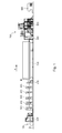
- a printing press in particular a web-fed rotary printing press for printing one or more webs B, has a plurality of assemblies 100; 200; 300; 450; 500; 600; 700; 800; 900 for supply, for printing and for further processing.
- Additional printing units 300 can be provided for the printing units 300 (eg four pieces for four-color printing) provided by default for multi-color printing, which can then also be used, for example, alternately with one or more of the remaining printing units 300 for the flying printing form change.
- a coating unit 450 may be provided in the web path.
- the web B passes through a dryer 500 and is optionally cooled again in a cooling unit 600, if the drying takes place in a thermal manner.
- a drying unit 600 After the dryer 500, in or after the cooling unit 600, at least one further, not shown in FIG. 1 conditioning, such. B. a coating device and / or a Wiederbefeuchtung be provided.
- the web B can be fed via a superstructure 700 to a folding apparatus 800.
- the superstructure 700 has at least one not shown in Fig. 1 silicone work, a slitting and a turning device and a funnel unit. The said silicone work can also be before the superstructure 700, z. B. be arranged in the region of the cooling unit 600.
- the superstructure 700 may further comprise a perforator, not shown in FIG. 1, a gluing unit, a numbering unit and / or a plow folder. After passing through the superstructure 700, the web B will become Part tracks are guided in a folder 800.
- the printing machine additionally has a separate cross cutter 900, z. B. a so-called. Plano boom 900, in which a, for example, not guided by the folder 800 web B cut into format sheets and possibly stacked or designed.
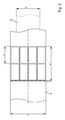
- the aggregates 100; 200; 300; 450; 500; 600; 700; 800; 900 of the printing press have an effective width transverse to the transport direction T of the web B, which is the processing of webs B of a maximum width b (FIG. 2) of z. B. up to 1,000 mm allowed.
- effective width is the respective width or clear width of the directly or indirectly cooperating with the web B components (eg, roller, cylinder, implementation, sensors, travel paths, etc.) of the units 100; 200; 300; 450; 500; 600; 700; 800; 900 so that the web B can be processed, conditioned and conveyed in its full width b.
- the aggregates 100; 200; 300; 450; 500; 600; 700; 800; 900 in their functionality (material supply, rail transport, sensors, further processing) designed such that even partial width webs B 'in the printing press down to a width b' of only 400 mm are processed.
- the aggregates 100 defining or processing a section length a; 200; 300; 450; 500; 600; 700; 800; 900 are configured to define, for example, a section length a lying between 540 and 700 mm on the path B.
- the section length a is between 540 and 630 mm.
- the section length a is 620 ⁇ 10 mm.
- the units 100; 200; 300; 450; 500; 600; 700; 800; 900 designed so that with a few changes, the printing machine with optional section length 546 mm, 578 mm, 590 mm or 620 mm is executable.
- the section length a is, for example, standard with four stationary printed pages, z. B. DIN A4, in the transverse direction of the web B side by side and two printed pages (for example, a length s) in the longitudinal direction one behind the other.
- z. B. DIN A4 in the transverse direction of the web B side by side
- two printed pages for example, a length s
- other page numbers per section length a are possible.
- the press For multicolor printing of web B; B 'the press has several, z. B. at least four, in particular five substantially equally equipped printing units 300.
- the printing units 300 are preferably arranged side by side and are of the web B; Go through B 'horizontally.
- the printing unit 300 is preferably used as a printing unit 300 for offset printing, in particular as a double printing unit 300 or as an I-printing unit 300 with two printing units 301, z. B. two offset printing units 301 executed for the two-sided printing in the so-called. Rubber-against-rubber operation.
- At least one of the printing units 300 are at least in the lower region, and optionally in the upper region, upstream and downstream rollers 302, by means of which an incoming web B; B 'can be guided around the printing unit 300 at the bottom or at the top, a web B guided around an upstream printing unit 300; B 'can be carried out by the printing unit 300, or a web B performed by the printing unit 300; B 'is guided around the downstream printing unit 300.
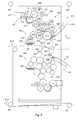
- Fig. 3 shows schematically the arrangement of two over the web B; B 'co-operating printing units 301, each with one as a transfer cylinder 303 and designed as a forme cylinder 304 printing cylinder 303; 304 (in short: cylinder 303, 304), an inking unit 305 and a dampening unit 306.
- the printing unit 300 has per form cylinder 304 devices for semi or fully automatic plate feeder 307 or change a printing forme 310th
- At least one or more printing units 300 have additional guide elements 308 close to and after the nip point of the printing unit 300. If a printing unit 300 without printing and without contact between web B; B 'and transfer cylinders 303 are passed through, the web guide shown in broken lines in FIG. 3 using the guide elements 308 is advantageous.
- the web B; B 'passes through the nip so as to be at an angle of 80 ° to 100 °, e.g., 80 ° to 100 °, with a line connecting axes of rotation of the two transfer cylinders 303. forms about 90 °.
- the guide elements 308 are preferably designed as luftum Whyte rods or rollers. This reduces the risk of abrasion of previously freshly printed paint.
- each transfer cylinder 303 is assigned a washing device 309.
- the washing device 309 By means of the washing device 309, the elastic surface of the transfer cylinder 303 can be cleaned.
- the cylinders 303; 304 each have a circumference between 540 and 700 mm, wherein preferably form and transfer cylinder 303; 304 have the same extent.
- the circumferences are between 540 and 630 mm.
- the section length a is 620 ⁇ 10 mm.
- the printing unit 300 is designed in such a way that, with a few changes, cylinders 303; 304 with a circumference of 546 mm, 578 mm, 590 mm or 620 mm is executable.
- the cylinder 303; 304 and an adjustment of the drive (lever, s.u).
- the transfer cylinder 303 has on its circumference at least one elevator, not shown, which is held in at least one axially extending on the lateral surface channel.
- the transfer cylinder 303 has only one over the effective length or substantially over the entire printing width of the web B; B 'reaching and substantially (except for a shock or a channel opening) to the entire circumference of the transfer cylinder 303 reaching elevator.
- the elevator is preferably embodied as a so-called metal printing blanket, which has an elastic layer (eg rubber) on a substantially dimensionally stable carrier layer, eg. B. a thin metal plate having. The ends of this elevator are now introduced through an opening on the lateral surface in the channel and friction or held there form-fitting.
- the ends are bent / folded (eg in the region of its leading end by approximately 45 ° and in the region of its trailing end by approximately 135 °). These ends extend through an opening of a channel extending axially over the entire width of the transfer cylinder 303, which, for example, likewise has a locking, clamping or tensioning device.
- the opening to the channel has in the region of the lateral surface in the circumferential direction of the cylinder 304 preferably a width of 1 to 5 mm, in particular less than or equal to 3 mm.
- the clamping is advantageously pneumatically actuated, z. B. as one or more pneumatically actuated lever, which are biased in the closed state by spring force against the reaching into the channel trailing end executed.
- a pressurizable medium is preferably used hose.
- the inking unit 305 has in addition to a color feeder, z. B. a color box 311 with a regulator 312 for regulating the flow of color, a plurality of rollers 313 to 325 on.
- the ink feed can also be designed as a doctor bar.
- the ink passes in juxtaposed rollers 313 to 325 from the ink fountain 311 on the ductor roller 313, the film roller 314 and a first ink roller 315 on a first distribution cylinder 316.
- the color passes depending on the operation of the inking unit 305 (see below), at least an ink roller 317 to 320 on at least one further distribution cylinder 321; 324 and from there via at least one application roller 322; 323; 325 on the surface of the forme cylinder 304.
- the color of the first distribution cylinder 316 passes through various possible ways either or simultaneously (in series or in parallel) via two further distribution cylinders 321; 324 to the applicator rollers 322; 323; 325th
- this is in a first position (solid) can be brought, in which it decreases the color of the first distribution cylinder 316 and the second impression cylinder 324 and at least the applicator roll 325 to the forme cylinder 304.
- This path is in principle independent of below described paths of the color from the first distribution cylinder 316 or from the second distribution cylinder 324 via the inking roller 318 and a third distribution cylinder 321 to the forme cylinder 304.
- a second position shown in solid color of the inking roller 317 (dashed lines) is this from the downstream distribution cylinder 324 turned off, the path of color over the second distribution cylinder 324 is interrupted.
- the second distribution cylinder 324 may simultaneously with a roller 328, z. B. applicator roller 328, the dampening unit 306 act together.
- the second distribution cylinder 324 located fluid (ink and / or fountain solution) then - the rollers 324, 325, 328 and the cylinder 304 are adjusted to each other accordingly - are delivered simultaneously via the applicator roller 325 and 328 to the forme cylinder 304.
- the ink roller 318 is also advantageous in two positions can be brought.
- a first position shown in solid line
- the inking roller 318 removes the ink from the second dispensing cylinder 324, which receives the ink from the first dispensing cylinder 316 via the inking roller 317 (located in its first position).
- the color if necessary via further ink rollers 319; 320, a third distribution cylinder 321, and from there via at least one application roller 322; 323 fed to the forme cylinder 304.
- a second position dashex roller 318
- This second position of the inking roller 318 is particularly important when the inking roller 317 is in its second (dashed) position.
- the movable applicator roll 318 can thus be a direct ink path via two arranged in series distribution cylinder 316; 321 or three serially arranged distribution cylinders 316; 321; 324 - the former irrespective of whether, in addition to this path, the o. G. first color path is realized via the second distribution cylinder 324 or not.
- the forme cylinder 304 is conveyed via a first, front application path from the second distribution cylinder 324 via one or possibly two application rollers 325 (328) and a second, rearward application path from the third distribution cylinder 324 via one or more associated application rollers 322; 323 supplied with paint.
- the term "front” and “rear” order path refers to the order of contact upon rotation of the plate cylinder 304 after ink delivery to the transfer cylinder 303. *** "
- the application roller 318 can be brought into a first position (dashed line) in which it decreases the ink from the first distribution cylinder 316 and via the application rollers 319; 320 feeds the second distribution cylinder 321.
- the applicator roll 318 removes the ink from a third dispensing cylinder 324 which receives the ink from the first dispensing cylinder 316 via the ink roller 317.
- the roller 318 is the inking behavior of the forme cylinder 304 through the inking unit 305 changeable and adjustable.
- first mode of operation in which the roller 318 is in the first position (shown in phantom in Fig. 3), more color is transferred to the "back" application path via the second group of rollers 319; 320; 321; 322; 323 (third distribution cylinder 321 and associated inking and application rollers 319, 320, 322, 323) and from there to the form cylinder 304 as in the mode of operation in which the roller 318 is in its second position.
- the ink for the rear application path is only removed by the second distribution cylinder 324.
- the ink application over the first group of rollers 324 is reduced or increased in a reverse manner; 325 and possibly 328 from the second distribution cylinder 324 forth to form cylinder 304.
- rollers or Reibzylindern are, unless stated otherwise, here those rollers or distribution cylinders understood that in separately operated inking and dampening unit in its basic function, d. H. in this example, a distribution cylinder 329 in the dampening unit 306 and three distribution cylinders 316; 321; 324, are assigned in the inking unit 305 with separate dampening solution and inking.
- the roller 328 can preferably be brought into two operating positions, wherein it is positioned in a first position (shown in solid line) on the second distribution cylinder 324 as shown above and shown in dashed lines in a second position ) is turned off by this.
- the contact can be produced by the application roller 328 of the dampening unit 306 onto the distribution cylinder 324 ("the inking unit" 305), where a color dampening solution emulsion is formed. In both positions, however, it acts with the plate cylinder 304 on the one, and with another roller 329 of the dampening unit 306, z.
- a friction roller 329 in particular a iridescent chrome roller 329 together.
- the chrome roller 329 receives the dampening solution from a moistening device, for. B. a roller 330, in particular a fountain roller 330, which in a dampening solution supply 332, z. B. a water tank, surfaced. Under the water tank a drip tray 335 is preferably arranged for collecting condensation forming on the water box, which can be heated in an advantageous embodiment, for. B. by means of heating coil is executed.
- rollers 317; 318; 328 Under the mobility of the rollers 317; 318; 328 is not to be understood as the usual adjustability for adjustment purposes, but the operational mobility to change from one to the other operating position. Ie. Manual or actuatable actuating means and / or stops (eg adjustable) are provided for both the one and the other operating positions. Furthermore, there is a larger allowable travel or before the roller assembly is chosen so that the two layers can be reached by the usual travel.
- the chrome roller 329 and the roller 330 are each movable in a direction perpendicular to its axis, for. B. in levers, stored so that the position of the applicator roll 328 in o. G. Way is changeable.
- the distribution cylinders 316; 321; 324 of the inking unit 305 and the roller 329 of the dampening unit 306 are axially movably mounted in side frames (not shown in FIG. 3) so that they can exert a traversing movement.
- the traversing movement takes place for the distribution cylinder 316; 321; 324 and the roller 329 coupled via corresponding gear coupled to the respective rotary drive.
- a storage is also provided, which allows a traversing.
- the axial movement is caused only by friction of the cooperating lateral surfaces and not via a corresponding traversing gear.
- such a degree of freedom enabling storage in the axial direction can also be provided for the two applicator rollers 322 and 325.
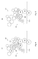
- Fig. 4 is shown schematically (only for the upper printing unit 301) a mode of operation, wherein the roller 317 is turned off by the second distribution cylinder 324 (shown in broken lines), remains employed on the distribution cylinder 316 (shown in phantom), and in a further development at the same time Roller 314 is employed. At the same time, the roller 318 is detached from the second distribution cylinder 324 and is set against the first distribution cylinder 316. The ink path thus takes place via the first and third distribution cylinders 316; 321.
- the application roller 328 of the dampening unit 306 is in contact with the second distribution cylinder 324 so that a dampening agent application takes place directly and over a total of five rollers 324, 325 and 328 to 330 (five-roller dampening unit).
- One of three friction cylinders 316; 321; 324 of the inking unit 305 and an applicator roll 325 can thus be assigned to the dampening unit 306 by adjustability of the roller 317 and optionally 318.
- This mode of operation of inking and dampening unit 305 is particularly suitable; 306 when operating with special colors, in particular for paints with high metallic contents, and / or if for other reasons (eg emulsifying behavior and / or unnecessary roll contamination) no indirect dampening should take place.
- Fig. 5 shows schematically (only for the upper printing unit 301) a mode of operation, wherein the roller 328 from the second distribution cylinder 324 is turned off (shown in solid line), but remains employed on the roller 329 and on the forme cylinder 304. Moistening takes place only via the three rollers 328 to 330.
- the applicator rollers 322; 323; 325 parked by the forme cylinder 304 (indicated by arrows) and the drive of the inking unit 305th z.
- the juxtaposed rollers 313, 314 and 315 are arranged in such a way that in Anstelllage connections V1, V2 of the axes of rotation of the rollers 313 and 315, each with the axis of rotation of the roller 314 is substantially a right angle of about 90 °, d. H. 80 ° ⁇ ⁇ 100 °, in particular 85 ° ⁇ ⁇ 95 °.
- a connection V3 between contact point, z. B. the point of contact of the actuator 312, on the roller 313 with the axis of rotation of the roller 313 also substantially a right angle, d. H.
- the arrangement of the rollers 313 and 314 is selected such that the axis of rotation of the roller 314 designed as a film roller 314 lies above the axis of rotation of the ductor roller 313.
- the arrangement is chosen so that, taking into account the direction of rotation of the rollers 313; 314 the incoming side of the nip is lower than the outgoing side.
- the film roller 314 is executed on its lateral surface with a surface structure 344, which only an average bearing surface 346, z. B. elevations 346, from 5 to 15%, in particular 5 to 11% in the effective range and intervening recesses 347; 348 has.
- the stated proportion of the bearing surface 346 on the entire effective lateral surface can in principle be implemented in a very wide variety of ways by evenly distributed recesses, cutouts, etc. of the most varied patterns.
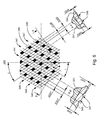
- Fig. 6 shows schematically a particularly advantageous embodiment of the surface structure 344, which is to manufacture in a simple manner and also shows a favorable behavior with respect to the recording and dispensing of the color.
- the surface structure 344 of the film roller 314 consists of two groups of grooves 347 extending in a straight line on the development of the roller 314; 348.
- the grooves 347; 348 of each groove subgroup parallel to each other and are evenly distributed over the peripheral surface of the film roll 314.
- the grooves 347 of the first groove subgroup extend at a helix angle y which is in the range of z. B. 20 ° and 40 °, in particular 25 ° and 35 °, is distributed relative to the longitudinal axis of the film roller 314 over the peripheral surface of the film roller 314.
- the grooves 348 of the second groove subgroup extend at a helix angle ⁇ in the range of z. B.
- the grooves 347; 348 of the two groove subsets are arranged so that they intersect on the peripheral surface. By the intersecting grooves 347; 348 are between the grooves 347; 348 the diamond-shaped elevations 346 formed.
- a depth t347; t348 of the grooves 347; 348 is, at least at its lowest point, advantageously 0.2 to 0.6 mm, the depths t347; t348 of the two grooves 347; 348 are preferably made substantially the same size.
- a width b347 of the grooves 347 is advantageously 1.0 to 1.8 mm, a width b348 of the grooves 348 advantageously 0.7 to 1.6 mm.
- the mutually parallel grooves 347; 348 should be spaced apart such that the side lengths of the diamond-shaped projections 346 on the one, longer side (eg, adjacent to the groove 348) are 0.5 to 1.0 mm, and on the other, shorter side (e.g. adjacent to the groove 347) is 0.4 to 0.7 mm.
- the production of the grooves 347; 348 is carried out in an advantageous embodiment by removal of surface material 349, z. B. by milling.
- they essentially have a circular arc section-shaped cross-section.
- This circular arc section in turn has for the wider grooves 347 z.
- the grooves of the grooves 347 running on the lateral surface are then, for example, at a distance a347 of the center lines of 1.85 to 2.45 mm, the milling of the grooves 348 for example at a distance a348 of the center lines of 1.35 to 1.95 mm performed.
- the surface material 349 is, for example, as a plastic (for example polyamide), in particular as a sintered-coated plastic on a metallic roller base body 351, for. B. a metal pipe, not shown, with a preferred wall thickness of 7.0 to 12 mm executed.
- a thickness d349 (uninjured, that is in the region of the elevation 346) of the surface material 349 is advantageously 0.8 to 1.2 mm.
- the inking unit 305 advantageously has, in addition to the mentioned rollers 313 to 325, at least one further roller 326, by means of which ink can be removed from the inking unit 305 in the ink path, in particular in front of the first distribution cylinder 316. This takes place by means of this roller 326 itself, or, as shown, on a roller 327 which cooperates with it, a corresponding removal device 333 can be set (FIG. 3).
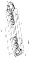
- Fig. 7 shows the removal device 333 as it cooperates with the roller 327 (also possible roller 326, but adapted to the direction of rotation).
- the roller 327 also possible roller 326, but adapted to the direction of rotation.
- the roller 327 is a plurality of z. B. as stripping elements 334 executed sections 334, z. B. stripping elements 334.1 to 334.10, to the lateral surface adjustable.
- the removal device 333 has at least one such stripping element 334, at least in one edge region of the roller 327.
- In the region of a central zone 340 (inactive zone 340) of the roller 327 z. B. no stripping elements 334 provided.
- stripping elements 334 may also be provided in the zone 340, which, however, are adjusted or set as required such that they do not come into contact with the jacket surface when the removal device 333 is started.
- stripping elements 334 in particular in the edge region, can be taken in the corresponding portion of the roller 327 color and z. B. collected in a container 336 and recycled in a further development of the ink supply.
- This section represents a zone 331, in particular contact zone 331, which is active with respect to the color removal.
- the roller 327 thus becomes colored in this section of the roller 315, and thus also approximately in the subsequent ink path up to the forme cylinder 304 (partly also via reverse coloring) withdrawn (sink).
- a color flow in the inking unit 305 can thus be reduced to a web width b; b 'of the web B to be printed; B 'are set.
- a group of several stripping elements 334 in this case five stripping elements 334.1 to 334.5 and 334.6 to 334.10, are arranged side by side substantially flush with one another from each edge region of the roller 327. Between the two groups, a section (corresponding to a minimum width b 'of a web B' to be printed) without stripping elements 334 may be provided.
- the stripping elements 334 are arranged in the embodiment of FIG. 7 on a common spindle 337 and are by pivoting the spindle 337 by means of a drive 338, here on both sides depending on a pressure actuated cylinder 338 on or off.
- the definition of the effective stripping elements 334 takes place here via the manual placement of knives 339 via respective adjusting means 341, z. B. Lever mechanisms 341.
- the placement of the knife 339 can in an advantageous development, however, also by individual drives, for example by means of small pressure medium cylinder, magnetic, piezoelectric or motor, take place.
- Advantageous here are remotely operated drives, for example, from a control room and / or a machine control ago.
- the stripping elements 334 are not turned on or off altogether, but a place is done for each stripping element 334 individually, z. B. by individual drives, for example by means of small pressure cylinder, magnetic, piezoelectric or motor. Remote-operated drives, for example from a control station and / or a machine control, are also advantageous here.
- a procedure described below in the setting of the inking unit 305 is advantageous: when adjusting the color flow to the product and / or the width b; b 'of the web B to be printed; B ', the ink flow from the ink fountain 311 into the inking unit 305 is made zone by zone by setting passage gaps between the ink fountain 311 and the first roller 313 (Fig. 8). This is done z. B. remotely operated by placing colorimeters 343 by means not shown in Fig. 8 drives. If a centrally running web B 'printed, which is only partially wide, z. B. basically each side of the roller 313 at least one of the color meter 343 closed.
- the number of basically due to the web width to be closed color meter 343 depends on the width b; b 'of the web B; B '.
- color meter be closed depending on the print image, i. H. from the color requirement in the respective zones of the area to be printed.
- the width of the web B; B 'dependent basic setting is now in an advantageous embodiment by the machine control automatically depending on the made of printing web width.
- This information is z.
- the information about the web width or the information about closed color meter 343 is now used to control the above drives for the individually operable stripping elements 334 or knife 339. Based on this information, the wiper elements 334 or knife 339 to be closed are determined and the corresponding drives are activated.
- the control of colorimeters 343 on one side and the knife 339 or stripping elements 334 on the other side may be based on common information - e.g. B. over the web width - also done in parallel.
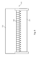
- the cylinders 303; 304 and the rollers 313 to 330 of inking and dampening unit 305; 306 are each frontally in or on side frames 352; 353 or frame walls 352; 353 stored (see Fig. 9). 9, however, only the rollers 329 and 330 are shown in FIG. 9 with their attachment and drive mimics described in greater detail below, as well as the main drive 354 of the printing unit 300, which is also explained below.
- One of the frame walls 352; 353, in particular that on the side of the main drive 354, is one or more parts designed such that a lockable cavity 356, z. B. lubricant space 356, can be formed, which extends at least over an area, the front side all cylinders 303; 304 and rotatably driven rollers covered.
- a detachable cover 357 for the cavity 356 is provided on the front side.
- the other frame wall 352 forms with a detachable, front side arranged cover 358 a cavity 359, in which inter alia, the switching and control devices 361 (dashed lines), z. B. in the form of a cabinet 361, the printing unit 300 are housed.
- the frontal arrangement of the switching and control devices 361, in contrast to the arrangement between the printing units 300 gives the advantage that the space between two printing units 300 can be walked on from both sides.
- One operating page of the printing press is thus freely selectable.
- This will continue supports that a longitudinal cross-piece 362 connecting the printing units 300 can optionally be arranged on the frame wall 352 or 353.
- a longitudinal cross-piece 362 connecting the printing units 300 is attached to one of the frame walls 352; 353, z. B. optionally, arranged.
- the projection 363 is advantageously integral with the side frame 352; 353 and is preferably produced in the production in a mold as so-called. Sprue 363.
- the sprue 363 points through it and the flight of the frame wall 352; 353 reaching holes for receiving bearings, not shown.
- the sprue 363 extends, in particular contiguous, over the frontal region of the forming and transfer cylinders 303; 304, but not over frontal areas of iridescent and / or changeable inking or dampening rollers.
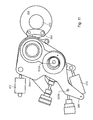
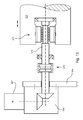
- the rollers 329 and 330 are inside on the frame walls 352; 353 in levers 364; 366 about a pivot axis S329 parallel to the respective axis of rotation; S330 pivotally mounted (see Fig. 11).
- the pivot axis S329 coincides with the rotational axis of the roller 330 and is moved with pivoting of the lever 364 with the roller 330.
- the pivot axis S330 of the roller 330 is fixed to the frame. Also with the respective lever 364; 366 connected and with the respective roller 329; 330 is moved per roller 329; 330 a rotary single drive 367; 368, in particular a drive motor 367; 368, provided which z. B.
- the drive motor 367; 368 is preferably as with respect to the speed controllable (in particular continuously) electric motor 367; 368, in particular three-phase motor 367; 368 executed.
- the setting of the speeds or the humidification can advantageously from the control center, z. B. from the color control desk take place, where it is displayed.
- the machine control is a correlation between machine speed and dampening or speed deposited by which the speed of the two rollers 329; 330, in particular the roller 330, can be predetermined.
- the lever 366 of the roller 330 may have an adjustable stop 365, by means of which it is supported in an adjusting position of the dampening unit 306 against a stop 370 of the applicator roller 328 cooperating with the roller 329.
- the respective lever 364; 366 is driven by a drive 372; 373, in particular pressurizable cylinders 372; 373, swiveling.
- the rollers 329; 330 are preferably on both sides in corresponding levers 364; 366 each with drives 372; 373 for the pivoting movement on the two frame walls 352; 353 stored (see Fig. 11).
- the roller 329 has on the end opposite the rotary drive a traverse drive 374, in particular a gear 374 for generating an axial traversing movement from the rotational movement.
- This gear 374 is preferably arranged outside the roller body in order to avoid selective generation of frictional heat in the roller 329.
- the gear 374 is on the drive side of the printing unit 300, ie in the same frame wall 353 as the main drive 354 and / or a drive train of the printing cylinder, the rotary drive of the rollers 329 and 330, however, on the opposite side, ie in Area of the frame wall 352.
- the transmission 374 may be arranged as an open, not specially lubricated transmission 374 in this.
- the roller 329 is on the side remote from the transmission 374 on a with the motor shaft via the corner gear 369 and an angle-compensating coupling 375, z. B. a curved tooth coupling, and a shaft 376 via z. B. as a bearing 377, in particular thrust bearing, trained coupling means 377th mounted such that a rotational movement transmitted, however, an axial movement of the roller 329 relative to the shaft 376 is possible (Fig. 13).
- the bearing 377 is advantageously designed as a torque transmitting ball bushing, wherein balls z. B. both in longitudinal grooves of the shaft 376 and bearing body run, transmit a torque, but hold the bearing body relative to the shaft 376 axially movable.
- the bearing body is, for example, secured against rotation with the roller body of the roller 329.
- FIG. 14 shows an advantageous embodiment of the transmission 374 in the region of the other end side of the roller 329, which is fundamentally designed based on the function of a cam mechanism with a curved circumferential groove 400 and an engaging stop 401.
- An outer sleeve 378 with internal teeth is fixedly connected to the lever 364 and carries the stop 401 (or the groove 400).
- Via a flexible but torsionally rigid connection 379 (articulated or flexible) is an inner sleeve 381, which carries the groove 400 (or the stopper 401), connected to a toothed ring 380 with external teeth.
- the toothed ring 380 is rotatably mounted on an eccentric 382, which is torsionally rigid but eccentric to the axis of rotation of the roller 329 via a shaft 385 connected thereto.
- the eccentric 382 revolves and rolls the toothed ring 380 in the lever-fixed internal toothing, with the inner sleeve 381 being set in rotation with respect to the lever-fixed outer sleeve 378.
- a reduction ratio between the rotation of the roller 329 and the inner sleeve 381 is determined by the teeth ratio between the inner teeth and the toothed ring 380.
- the drive of the cylinders 303 takes place; 304 of the printing unit 300 via a main drive 354, z. B. a frame-fixed electric motor 354, in particular via a respect to its angular position adjustable electric motor 354, which is advantageously carried out water-cooled.
- a frame-fixed electric motor 354 in particular via a respect to its angular position adjustable electric motor 354, which is advantageously carried out water-cooled.
- the electric motor 354 drives with its not visible in Fig. 15 pinion 383 (dashed arrow) not directly on a drive wheel 386; 387 one of the cylinders 303; 304, but via an intermediate gear 384.
- the idler 384 is mounted in a lever 388, which is mounted pivotably about a rotation axis R383 of the pinion 383 in principle.
- a fixed position of the electric motor 354 with respect to the frame wall 353 of the frame can be done for different sized printing units 300 in a simple manner to adapt to different cylinder circumferences (and thus different circumferences of the drive wheels 386, 387).
- the lever 388 is pivoted during assembly so that the intermediate gear 384 in optimal engagement with the respective drive wheel 386; 387 stands.
- Bolt 389 and corresponding, not shown bores (on the drive unit and / or in the frame wall 353) is provided, by means of which the aligned lever 388 can be fixed after assembly in the relevant position with respect to the frame wall 353 and / or the electric motor 354.
- the aligned lever 388 can be fixed after assembly in the relevant position with respect to the frame wall 353 and / or the electric motor 354.
- the lever 388 is fixed in a different angular position relative to the vertical than in a printing unit 300 or printing machine for a second format (section length a), wherein the electric motor 354 its position with respect to the frame wall 353.
- the drive from the idler 384 to any of the drive wheels 386; 387 done.
- the drive initially takes place on the drive wheel 387 of one of the two forme cylinders 304.
- the drive wheel 386 of the associated transfer cylinder 303 is driven from there to the other transfer cylinder 303 and ultimately to the second forme cylinder 304.
- the drive wheels 386; 387 are rotatable, z. B. via pins, with the respective cylinder 303; 304 connected.
- the rotary drive is effected on one or more rollers 313 to 327 of the associated inking unit 305.
- the ductor roller 313 has its own rotary drive, for. B. a separate, mechanically independent drive motor, not shown, on.
- the remaining rollers 314; 315; 317 to 320, 322; 323 and 325 to 327 of the inking unit 305 are rotationally driven only via friction (and optionally axially, see above).
- the idler gear 392 is preferably designed to be engaged or disengageable, so that the corresponding drive train and the forme cylinder 304 are mechanically separated from one another (the unillustrated drive train in the lower printing unit 301 takes place correspondingly).
- From the drive wheel 393 of the friction cylinder 324 is driven via a further intermediate gear 395 to a drive wheel 396 of the friction cylinder 316.
- the drive or intermediate wheels 392 to 396 are preferably designed as gears 392 to 396.
- the drive connections are designed such that an axial movement of the distribution cylinders 316; 321; 324 is possible.
- the printing unit 301 in an advantageous embodiment in each case the device 307 to - at least partially automated change of a printing plate 310 on the associated forme cylinder 304.
- the device is designed in two parts and has one in the region of a nip between form and transfer cylinder 303; 304 arranged pressing device 397, also called “Wechsel Halbautomat” 397, and a structurally separate magazine 398 with feeding and receiving devices for the printing plates 310 on.
- the printing unit 300 has a device for influencing the fan-out effect 399, ie for influencing a change in the transverse extent / width of the web B from printing location to printing location caused, for example, by the printing process (in particular the moisture).
- a device for influencing the fan-out effect 399 ie for influencing a change in the transverse extent / width of the web B from printing location to printing location caused, for example, by the printing process (in particular the moisture).
- at least one nozzle is arranged on a truss in such a way that from her escaping gas, in particular air, on the web B; B 'is directed.
- the web B; B ' is more or less wavy when passing through this area, depending on the magnitude of the current, resulting in a correction of the width b; b 'and the lateral alignment of each sub-area of the printed image result.
Landscapes
- Engineering & Computer Science (AREA)
- Mechanical Engineering (AREA)
- Inking, Control Or Cleaning Of Printing Machines (AREA)
- Manufacturing Of Printed Wiring (AREA)
- Printing Methods (AREA)
- Printers Or Recording Devices Using Electromagnetic And Radiation Means (AREA)
Applications Claiming Priority (3)
| Application Number | Priority Date | Filing Date | Title |
|---|---|---|---|
| DE10331595 | 2003-07-11 | ||
| DE10352616A DE10352616A1 (de) | 2003-07-11 | 2003-11-11 | Druckwerk einer Druckmaschine |
| EP04741969A EP1644194A2 (fr) | 2003-07-11 | 2004-07-07 | Groupe d'impression de machine d'impression |
Related Parent Applications (1)
| Application Number | Title | Priority Date | Filing Date |
|---|---|---|---|
| EP04741969A Division EP1644194A2 (fr) | 2003-07-11 | 2004-07-07 | Groupe d'impression de machine d'impression |
Publications (2)
| Publication Number | Publication Date |
|---|---|
| EP1864801A1 true EP1864801A1 (fr) | 2007-12-12 |
| EP1864801B1 EP1864801B1 (fr) | 2008-09-10 |
Family
ID=34081634
Family Applications (2)
| Application Number | Title | Priority Date | Filing Date |
|---|---|---|---|
| EP04741969A Withdrawn EP1644194A2 (fr) | 2003-07-11 | 2004-07-07 | Groupe d'impression de machine d'impression |
| EP07113071A Expired - Lifetime EP1864801B1 (fr) | 2003-07-11 | 2004-07-07 | Imprimé d'une presse |
Family Applications Before (1)
| Application Number | Title | Priority Date | Filing Date |
|---|---|---|---|
| EP04741969A Withdrawn EP1644194A2 (fr) | 2003-07-11 | 2004-07-07 | Groupe d'impression de machine d'impression |
Country Status (5)
| Country | Link |
|---|---|
| US (1) | US20060272527A1 (fr) |
| EP (2) | EP1644194A2 (fr) |
| AT (1) | ATE407803T1 (fr) |
| DE (2) | DE10352616A1 (fr) |
| WO (1) | WO2005007409A2 (fr) |
Families Citing this family (11)
| Publication number | Priority date | Publication date | Assignee | Title |
|---|---|---|---|---|
| DE102004023095A1 (de) * | 2004-05-05 | 2005-11-24 | Koenig & Bauer Ag | Umstellbares Fahrwerk |
| DE102005000782A1 (de) | 2005-01-05 | 2006-07-20 | Voith Paper Patent Gmbh | Trockenzylinder |
| DE102006020048A1 (de) * | 2006-04-26 | 2007-10-31 | Man Roland Druckmaschinen Ag | Druckwerk einer Druckeinheit einer Druckmaschine |
| WO2007134919A1 (fr) * | 2006-05-23 | 2007-11-29 | Koenig & Bauer Aktiengesellschaft | Mécanisme d'encrage de presse rotative comprenant un cylindre porte-film |
| JP5334365B2 (ja) † | 2006-10-23 | 2013-11-06 | 株式会社ミヤコシ | オフセット印刷機の湿し水装置 |
| DE102007006063B4 (de) | 2007-02-07 | 2009-10-01 | Koenig & Bauer Aktiengesellschaft | Druckwerk einer Rotationsdruckmaschine |
| US8327763B2 (en) * | 2007-02-07 | 2012-12-11 | Koenig & Bauer Aktiengesellschaft | Printing couple of a rotary printing press and a method for washing a dampening unit of a printing couple |
| DE102008009891A1 (de) * | 2008-02-19 | 2009-08-20 | Manroland Ag | Verfahren zum Einfärben einer Druckform in einer Verarbeitungsmaschine |
| DE102008009892B4 (de) * | 2008-02-19 | 2015-04-02 | manroland sheetfed GmbH | Verfahren zum Einfärben einer Druckform in einer Verarbeitungsmaschine |
| JP2009196269A (ja) * | 2008-02-22 | 2009-09-03 | Mitsubishi Heavy Ind Ltd | 輪転印刷機 |
| CN115107351B (zh) * | 2022-07-25 | 2024-01-26 | 东莞市源铁印刷机械有限公司 | 一种正反面印刷两用的印刷机 |
Citations (3)
| Publication number | Priority date | Publication date | Assignee | Title |
|---|---|---|---|---|
| DE2932105A1 (de) * | 1979-08-08 | 1981-02-12 | Roland Man Druckmasch | Farbwerk fuer eine offsetrotationsdruckmaschine |
| DE3641013A1 (de) * | 1986-04-21 | 1987-10-22 | Polygraph Leipzig | Brueckenwalzensteuerung an farb- und feuchtwerken in druckmaschinen |
| EP0895858A1 (fr) * | 1997-08-07 | 1999-02-10 | Kba-Planeta Ag | Tour d'impression d'une machine à imprimer |
Family Cites Families (11)
| Publication number | Priority date | Publication date | Assignee | Title |
|---|---|---|---|---|
| DE1243695B (de) * | 1964-10-27 | 1967-07-06 | Adamovske Strojirny Np | Farbwerk fuer Druckmaschinen |
| DE2106655A1 (de) * | 1971-02-12 | 1972-08-24 | Koenig & Bauer Schnellpressfab | Walzenfarbwerk für Rotationsdruckmaschinen |
| CH557238A (de) * | 1972-09-05 | 1974-12-31 | Maschf Augsburg Nuernberg Ag | Umsteuerbares druckwerk fuer rotations-offsetdruckmaschinen. |
| DE2902228C2 (de) * | 1979-01-20 | 1981-12-17 | M.A.N. Maschinenfabrik Augsburg-Nürnberg AG, 8900 Augsburg | Vorrichtung zum Zuführen von Flüssigkeit zum Plattenzylinder einer Offset-Rotationsdruckmaschine |
| DE3303988A1 (de) * | 1983-02-05 | 1984-09-13 | M.A.N.- Roland Druckmaschinen AG, 6050 Offenbach | Farbwerk |
| DD257990A1 (de) * | 1986-04-21 | 1988-07-06 | Polygraph Leipzig | Verfahren zum teilweisen entfernen von farbe aus dem farbwerk |
| DE4013740C3 (de) * | 1989-06-19 | 1999-04-08 | Heidelberger Druckmasch Ag | Verfahren und Vorrichtung zum schnellen Erreichen des Fortdruckzustands bei einer Offsetdruckmaschine |
| DE4012283A1 (de) * | 1990-04-17 | 1991-10-24 | Wifag Maschf | Farb- und feuchtwerk fuer ein umsteuerbares druckwerk einer rotations-offsetdruckmaschine |
| DE4230947B4 (de) * | 1992-09-16 | 2004-05-13 | Heidelberger Druckmaschinen Ag | Farbwerk für Rotationsdruckmaschinen |
| DE4439144C2 (de) * | 1994-11-03 | 1997-04-30 | Roland Man Druckmasch | Farbwerk einer Rotationsoffsetdruckmaschine |
| DE19956149A1 (de) * | 1999-11-23 | 2001-06-07 | Roland Man Druckmasch | Farbwerk für eine Druckmaschine |
-
2003
- 2003-11-11 DE DE10352616A patent/DE10352616A1/de not_active Withdrawn
-
2004
- 2004-07-07 DE DE502004008056T patent/DE502004008056D1/de not_active Expired - Fee Related
- 2004-07-07 WO PCT/EP2004/051376 patent/WO2005007409A2/fr not_active Ceased
- 2004-07-07 AT AT07113071T patent/ATE407803T1/de not_active IP Right Cessation
- 2004-07-07 US US10/564,290 patent/US20060272527A1/en not_active Abandoned
- 2004-07-07 EP EP04741969A patent/EP1644194A2/fr not_active Withdrawn
- 2004-07-07 EP EP07113071A patent/EP1864801B1/fr not_active Expired - Lifetime
Patent Citations (3)
| Publication number | Priority date | Publication date | Assignee | Title |
|---|---|---|---|---|
| DE2932105A1 (de) * | 1979-08-08 | 1981-02-12 | Roland Man Druckmasch | Farbwerk fuer eine offsetrotationsdruckmaschine |
| DE3641013A1 (de) * | 1986-04-21 | 1987-10-22 | Polygraph Leipzig | Brueckenwalzensteuerung an farb- und feuchtwerken in druckmaschinen |
| EP0895858A1 (fr) * | 1997-08-07 | 1999-02-10 | Kba-Planeta Ag | Tour d'impression d'une machine à imprimer |
Also Published As
| Publication number | Publication date |
|---|---|
| EP1864801B1 (fr) | 2008-09-10 |
| DE502004008056D1 (de) | 2008-10-23 |
| ATE407803T1 (de) | 2008-09-15 |
| WO2005007409A3 (fr) | 2005-07-07 |
| DE10352616A1 (de) | 2005-02-10 |
| US20060272527A1 (en) | 2006-12-07 |
| WO2005007409A2 (fr) | 2005-01-27 |
| EP1644194A2 (fr) | 2006-04-12 |
Similar Documents
| Publication | Publication Date | Title |
|---|---|---|
| DE102013217948B4 (de) | Druckmaschine für den Wertpapierdruck mit einem Orlof-Offsetdruckwerk | |
| EP3043997B1 (fr) | Procédé et dispositif pour régler des corps rotatifs de transport d'encre d'une machine à imprimer | |
| EP2195166A1 (fr) | Dispositif d'encrage d'une presse à imprimer | |
| EP1644191B1 (fr) | Machine d'impression rotative a bobines | |
| EP1864801B1 (fr) | Imprimé d'une presse | |
| WO2007134919A1 (fr) | Mécanisme d'encrage de presse rotative comprenant un cylindre porte-film | |
| EP2406077A1 (fr) | Unité d'impression d'une machine d'impression comportant au moins une imprimante | |
| EP1946923B1 (fr) | Rouleau avec mouvement de va-et-vient axial d'un sysème d'encragepour ou de mouillage | |
| EP2291288B1 (fr) | Dispositif dans un groupe imprimant d'une machine à imprimer | |
| EP1498264B1 (fr) | Imprimante | |
| EP2298554B1 (fr) | Imprimante pour l'impression de produits imprimés | |
| DE19848390B4 (de) | Rollenrotationsdruckmaschine für einen schnellen Produktionswechsel | |
| EP2114681B1 (fr) | Groupe d'impression d'une presse rotative et procédé de lavage d'un groupe de mouillage d'un groupe d'impression | |
| EP1740380A1 (fr) | Unite d'impression d'une imprimeuse rotative a bobines polychrome et procede d'utilisation | |
| EP2353864B1 (fr) | Encrier et unité d'impression d'une imprimante | |
| DE3443765A1 (de) | An- und abstellvorrichtung fuer farbwalzen in druckmaschinen | |
| DE102008001979A1 (de) | Antrieb einer Druckeinheit einer Druckmaschine | |
| DE3003642A1 (de) | Offsetdruckmaschine |
Legal Events
| Date | Code | Title | Description |
|---|---|---|---|
| PUAI | Public reference made under article 153(3) epc to a published international application that has entered the european phase |
Free format text: ORIGINAL CODE: 0009012 |
|
| AC | Divisional application: reference to earlier application |
Ref document number: 1644194 Country of ref document: EP Kind code of ref document: P |
|
| AK | Designated contracting states |
Kind code of ref document: A1 Designated state(s): AT BE BG CH CY CZ DE DK EE ES FI FR GB GR HU IE IT LI LU MC NL PL PT RO SE SI SK TR |
|
| 17P | Request for examination filed |
Effective date: 20071116 |
|
| GRAP | Despatch of communication of intention to grant a patent |
Free format text: ORIGINAL CODE: EPIDOSNIGR1 |
|
| GRAS | Grant fee paid |
Free format text: ORIGINAL CODE: EPIDOSNIGR3 |
|
| GRAA | (expected) grant |
Free format text: ORIGINAL CODE: 0009210 |
|
| AKX | Designation fees paid |
Designated state(s): AT BE BG CH CY CZ DE DK EE ES FI FR GB GR HU IE IT LI LU MC NL PL PT RO SE SI SK TR |
|
| AC | Divisional application: reference to earlier application |
Ref document number: 1644194 Country of ref document: EP Kind code of ref document: P |
|
| AK | Designated contracting states |
Kind code of ref document: B1 Designated state(s): AT BE BG CH CY CZ DE DK EE ES FI FR GB GR HU IE IT LI LU MC NL PL PT RO SE SI SK TR |
|
| REG | Reference to a national code |
Ref country code: GB Ref legal event code: FG4D Free format text: NOT ENGLISH |
|
| REG | Reference to a national code |
Ref country code: CH Ref legal event code: EP |
|
| REG | Reference to a national code |
Ref country code: IE Ref legal event code: FG4D Free format text: LANGUAGE OF EP DOCUMENT: GERMAN |
|
| REF | Corresponds to: |
Ref document number: 502004008056 Country of ref document: DE Date of ref document: 20081023 Kind code of ref document: P |
|
| PG25 | Lapsed in a contracting state [announced via postgrant information from national office to epo] |
Ref country code: SI Free format text: LAPSE BECAUSE OF FAILURE TO SUBMIT A TRANSLATION OF THE DESCRIPTION OR TO PAY THE FEE WITHIN THE PRESCRIBED TIME-LIMIT Effective date: 20080910 |
|
| NLV1 | Nl: lapsed or annulled due to failure to fulfill the requirements of art. 29p and 29m of the patents act | ||
| REG | Reference to a national code |
Ref country code: IE Ref legal event code: FD4D |
|
| PG25 | Lapsed in a contracting state [announced via postgrant information from national office to epo] |
Ref country code: BG Free format text: LAPSE BECAUSE OF FAILURE TO SUBMIT A TRANSLATION OF THE DESCRIPTION OR TO PAY THE FEE WITHIN THE PRESCRIBED TIME-LIMIT Effective date: 20081210 Ref country code: ES Free format text: LAPSE BECAUSE OF FAILURE TO SUBMIT A TRANSLATION OF THE DESCRIPTION OR TO PAY THE FEE WITHIN THE PRESCRIBED TIME-LIMIT Effective date: 20081221 Ref country code: IE Free format text: LAPSE BECAUSE OF FAILURE TO SUBMIT A TRANSLATION OF THE DESCRIPTION OR TO PAY THE FEE WITHIN THE PRESCRIBED TIME-LIMIT Effective date: 20080910 |
|
| PG25 | Lapsed in a contracting state [announced via postgrant information from national office to epo] |
Ref country code: CZ Free format text: LAPSE BECAUSE OF FAILURE TO SUBMIT A TRANSLATION OF THE DESCRIPTION OR TO PAY THE FEE WITHIN THE PRESCRIBED TIME-LIMIT Effective date: 20080910 Ref country code: RO Free format text: LAPSE BECAUSE OF FAILURE TO SUBMIT A TRANSLATION OF THE DESCRIPTION OR TO PAY THE FEE WITHIN THE PRESCRIBED TIME-LIMIT Effective date: 20080910 Ref country code: NL Free format text: LAPSE BECAUSE OF FAILURE TO SUBMIT A TRANSLATION OF THE DESCRIPTION OR TO PAY THE FEE WITHIN THE PRESCRIBED TIME-LIMIT Effective date: 20080910 Ref country code: PT Free format text: LAPSE BECAUSE OF FAILURE TO SUBMIT A TRANSLATION OF THE DESCRIPTION OR TO PAY THE FEE WITHIN THE PRESCRIBED TIME-LIMIT Effective date: 20090210 Ref country code: SK Free format text: LAPSE BECAUSE OF FAILURE TO SUBMIT A TRANSLATION OF THE DESCRIPTION OR TO PAY THE FEE WITHIN THE PRESCRIBED TIME-LIMIT Effective date: 20080910 |
|
| PLBE | No opposition filed within time limit |
Free format text: ORIGINAL CODE: 0009261 |
|
| STAA | Information on the status of an ep patent application or granted ep patent |
Free format text: STATUS: NO OPPOSITION FILED WITHIN TIME LIMIT |
|
| PG25 | Lapsed in a contracting state [announced via postgrant information from national office to epo] |
Ref country code: EE Free format text: LAPSE BECAUSE OF FAILURE TO SUBMIT A TRANSLATION OF THE DESCRIPTION OR TO PAY THE FEE WITHIN THE PRESCRIBED TIME-LIMIT Effective date: 20080910 Ref country code: DK Free format text: LAPSE BECAUSE OF FAILURE TO SUBMIT A TRANSLATION OF THE DESCRIPTION OR TO PAY THE FEE WITHIN THE PRESCRIBED TIME-LIMIT Effective date: 20080910 |
|
| 26N | No opposition filed |
Effective date: 20090611 |
|
| PGFP | Annual fee paid to national office [announced via postgrant information from national office to epo] |
Ref country code: FR Payment date: 20090722 Year of fee payment: 6 |
|
| PGFP | Annual fee paid to national office [announced via postgrant information from national office to epo] |
Ref country code: CH Payment date: 20090728 Year of fee payment: 6 Ref country code: GB Payment date: 20090722 Year of fee payment: 6 |
|
| PG25 | Lapsed in a contracting state [announced via postgrant information from national office to epo] |
Ref country code: SE Free format text: LAPSE BECAUSE OF FAILURE TO SUBMIT A TRANSLATION OF THE DESCRIPTION OR TO PAY THE FEE WITHIN THE PRESCRIBED TIME-LIMIT Effective date: 20081210 |
|
| BERE | Be: lapsed |
Owner name: KOENIG & BAUER A.G. Effective date: 20090731 |
|
| PG25 | Lapsed in a contracting state [announced via postgrant information from national office to epo] |
Ref country code: MC Free format text: LAPSE BECAUSE OF NON-PAYMENT OF DUE FEES Effective date: 20090731 |
|
| PGFP | Annual fee paid to national office [announced via postgrant information from national office to epo] |
Ref country code: IT Payment date: 20090723 Year of fee payment: 6 |
|
| PG25 | Lapsed in a contracting state [announced via postgrant information from national office to epo] |
Ref country code: PL Free format text: LAPSE BECAUSE OF FAILURE TO SUBMIT A TRANSLATION OF THE DESCRIPTION OR TO PAY THE FEE WITHIN THE PRESCRIBED TIME-LIMIT Effective date: 20080910 |
|
| PG25 | Lapsed in a contracting state [announced via postgrant information from national office to epo] |
Ref country code: BE Free format text: LAPSE BECAUSE OF NON-PAYMENT OF DUE FEES Effective date: 20090731 Ref country code: DE Free format text: LAPSE BECAUSE OF NON-PAYMENT OF DUE FEES Effective date: 20100202 |
|
| PG25 | Lapsed in a contracting state [announced via postgrant information from national office to epo] |
Ref country code: GR Free format text: LAPSE BECAUSE OF FAILURE TO SUBMIT A TRANSLATION OF THE DESCRIPTION OR TO PAY THE FEE WITHIN THE PRESCRIBED TIME-LIMIT Effective date: 20081211 |
|
| PG25 | Lapsed in a contracting state [announced via postgrant information from national office to epo] |
Ref country code: AT Free format text: LAPSE BECAUSE OF NON-PAYMENT OF DUE FEES Effective date: 20090707 |
|
| PG25 | Lapsed in a contracting state [announced via postgrant information from national office to epo] |
Ref country code: FI Free format text: LAPSE BECAUSE OF FAILURE TO SUBMIT A TRANSLATION OF THE DESCRIPTION OR TO PAY THE FEE WITHIN THE PRESCRIBED TIME-LIMIT Effective date: 20080910 |
|
| REG | Reference to a national code |
Ref country code: CH Ref legal event code: PL |
|
| GBPC | Gb: european patent ceased through non-payment of renewal fee |
Effective date: 20100707 |
|
| REG | Reference to a national code |
Ref country code: FR Ref legal event code: ST Effective date: 20110331 |
|
| PG25 | Lapsed in a contracting state [announced via postgrant information from national office to epo] |
Ref country code: CH Free format text: LAPSE BECAUSE OF NON-PAYMENT OF DUE FEES Effective date: 20100731 Ref country code: LI Free format text: LAPSE BECAUSE OF NON-PAYMENT OF DUE FEES Effective date: 20100731 Ref country code: LU Free format text: LAPSE BECAUSE OF NON-PAYMENT OF DUE FEES Effective date: 20090707 |
|
| PG25 | Lapsed in a contracting state [announced via postgrant information from national office to epo] |
Ref country code: FR Free format text: LAPSE BECAUSE OF NON-PAYMENT OF DUE FEES Effective date: 20100802 Ref country code: IT Free format text: LAPSE BECAUSE OF NON-PAYMENT OF DUE FEES Effective date: 20100707 |
|
| PG25 | Lapsed in a contracting state [announced via postgrant information from national office to epo] |
Ref country code: HU Free format text: LAPSE BECAUSE OF FAILURE TO SUBMIT A TRANSLATION OF THE DESCRIPTION OR TO PAY THE FEE WITHIN THE PRESCRIBED TIME-LIMIT Effective date: 20090311 |
|
| PG25 | Lapsed in a contracting state [announced via postgrant information from national office to epo] |
Ref country code: GB Free format text: LAPSE BECAUSE OF NON-PAYMENT OF DUE FEES Effective date: 20100707 |
|
| PG25 | Lapsed in a contracting state [announced via postgrant information from national office to epo] |
Ref country code: TR Free format text: LAPSE BECAUSE OF FAILURE TO SUBMIT A TRANSLATION OF THE DESCRIPTION OR TO PAY THE FEE WITHIN THE PRESCRIBED TIME-LIMIT Effective date: 20080910 |
|
| PG25 | Lapsed in a contracting state [announced via postgrant information from national office to epo] |
Ref country code: CY Free format text: LAPSE BECAUSE OF FAILURE TO SUBMIT A TRANSLATION OF THE DESCRIPTION OR TO PAY THE FEE WITHIN THE PRESCRIBED TIME-LIMIT Effective date: 20080910 |