EP1864836B1 - Dispositif destiné au réglage en hauteur du montage de véhicules automobiles - Google Patents
Dispositif destiné au réglage en hauteur du montage de véhicules automobiles Download PDFInfo
- Publication number
- EP1864836B1 EP1864836B1 EP07005425.9A EP07005425A EP1864836B1 EP 1864836 B1 EP1864836 B1 EP 1864836B1 EP 07005425 A EP07005425 A EP 07005425A EP 1864836 B1 EP1864836 B1 EP 1864836B1
- Authority
- EP
- European Patent Office
- Prior art keywords
- pressure
- setting
- piston
- spring
- base plate
- Prior art date
- Legal status (The legal status is an assumption and is not a legal conclusion. Google has not performed a legal analysis and makes no representation as to the accuracy of the status listed.)
- Not-in-force
Links
Images

Classifications
-
- B—PERFORMING OPERATIONS; TRANSPORTING
- B60—VEHICLES IN GENERAL
- B60G—VEHICLE SUSPENSION ARRANGEMENTS
- B60G11/00—Resilient suspensions characterised by arrangement, location or kind of springs
- B60G11/14—Resilient suspensions characterised by arrangement, location or kind of springs having helical, spiral or coil springs only
- B60G11/16—Resilient suspensions characterised by arrangement, location or kind of springs having helical, spiral or coil springs only characterised by means specially adapted for attaching the spring to axle or sprung part of the vehicle
-
- B—PERFORMING OPERATIONS; TRANSPORTING
- B60—VEHICLES IN GENERAL
- B60G—VEHICLE SUSPENSION ARRANGEMENTS
- B60G15/00—Resilient suspensions characterised by arrangement, location or type of combined spring and vibration damper, e.g. telescopic type
- B60G15/02—Resilient suspensions characterised by arrangement, location or type of combined spring and vibration damper, e.g. telescopic type having mechanical spring
- B60G15/06—Resilient suspensions characterised by arrangement, location or type of combined spring and vibration damper, e.g. telescopic type having mechanical spring and fluid damper
- B60G15/062—Resilient suspensions characterised by arrangement, location or type of combined spring and vibration damper, e.g. telescopic type having mechanical spring and fluid damper the spring being arranged around the damper
- B60G15/063—Resilient suspensions characterised by arrangement, location or type of combined spring and vibration damper, e.g. telescopic type having mechanical spring and fluid damper the spring being arranged around the damper characterised by the mounting of the spring on the damper
-
- B—PERFORMING OPERATIONS; TRANSPORTING
- B60—VEHICLES IN GENERAL
- B60G—VEHICLE SUSPENSION ARRANGEMENTS
- B60G17/00—Resilient suspensions having means for adjusting the spring or vibration-damper characteristics, for regulating the distance between a supporting surface and a sprung part of vehicle or for locking suspension during use to meet varying vehicular or surface conditions, e.g. due to speed or load
- B60G17/02—Spring characteristics, e.g. mechanical springs and mechanical adjusting means
- B60G17/027—Mechanical springs regulated by fluid means
- B60G17/0272—Mechanical springs regulated by fluid means the mechanical spring being a coil spring
-
- B—PERFORMING OPERATIONS; TRANSPORTING
- B60—VEHICLES IN GENERAL
- B60G—VEHICLE SUSPENSION ARRANGEMENTS
- B60G2202/00—Indexing codes relating to the type of spring, damper or actuator
- B60G2202/30—Spring/Damper and/or actuator Units
- B60G2202/31—Spring/Damper and/or actuator Units with the spring arranged around the damper, e.g. MacPherson strut
- B60G2202/312—The spring being a wound spring
-
- B—PERFORMING OPERATIONS; TRANSPORTING
- B60—VEHICLES IN GENERAL
- B60G—VEHICLE SUSPENSION ARRANGEMENTS
- B60G2202/00—Indexing codes relating to the type of spring, damper or actuator
- B60G2202/40—Type of actuator
- B60G2202/41—Fluid actuator
- B60G2202/413—Hydraulic actuator
-
- B—PERFORMING OPERATIONS; TRANSPORTING
- B60—VEHICLES IN GENERAL
- B60G—VEHICLE SUSPENSION ARRANGEMENTS
- B60G2204/00—Indexing codes related to suspensions per se or to auxiliary parts
- B60G2204/10—Mounting of suspension elements
- B60G2204/12—Mounting of springs or dampers
- B60G2204/124—Mounting of coil springs
- B60G2204/1242—Mounting of coil springs on a damper, e.g. MacPerson strut
-
- B—PERFORMING OPERATIONS; TRANSPORTING
- B60—VEHICLES IN GENERAL
- B60G—VEHICLE SUSPENSION ARRANGEMENTS
- B60G2204/00—Indexing codes related to suspensions per se or to auxiliary parts
- B60G2204/40—Auxiliary suspension parts; Adjustment of suspensions
- B60G2204/44—Centering or positioning means
- B60G2204/4402—Spacers or shims
-
- B—PERFORMING OPERATIONS; TRANSPORTING
- B60—VEHICLES IN GENERAL
- B60G—VEHICLE SUSPENSION ARRANGEMENTS
- B60G2206/00—Indexing codes related to the manufacturing of suspensions: constructional features, the materials used, procedures or tools
- B60G2206/01—Constructional features of suspension elements, e.g. arms, dampers, springs
- B60G2206/90—Maintenance
- B60G2206/91—Assembly procedures
- B60G2206/911—Assembly procedures using a modification kit
-
- B—PERFORMING OPERATIONS; TRANSPORTING
- B60—VEHICLES IN GENERAL
- B60G—VEHICLE SUSPENSION ARRANGEMENTS
- B60G2500/00—Indexing codes relating to the regulated action or device
- B60G2500/20—Spring action or springs
-
- B—PERFORMING OPERATIONS; TRANSPORTING
- B60—VEHICLES IN GENERAL
- B60G—VEHICLE SUSPENSION ARRANGEMENTS
- B60G2500/00—Indexing codes relating to the regulated action or device
- B60G2500/30—Height or ground clearance
Definitions
- the invention relates to a device for height adjustment of the construction of motor vehicles according to the preamble of claim 1.
- Such a device describes, for example, the JP 10217737 A in which the construction of motor vehicles by means of two separately or jointly hydraulically actuated actuator piston in three stages with respect to the road surface is height adjustable.
- the pressure supply takes place via two separately controllable pressure lines, whereby the one pressure line must be flexible and structurally unfavorable to be laid by the suspension spring.
- the JP 10 250 338 A is a generic height adjustment known with an inner actuating piston and an outer actuating piston.
- the inner actuating piston is made of solid material.
- the outer actuating piston is cup-shaped with a closed bottom, which limits the pressure chamber. By the height adjustment device no piston rod is guided.
- the object of the invention is to propose a device for height adjustment of the generic type, which is technically favorable in terms of control engineering and production, and which enables a simpler pressure supply of the hydraulic chambers. Furthermore, a compatible suspension spring shock absorber connection without height adjustment to be created.
- the pressure supply of the two hydraulic chambers of the separately adjustable adjusting pistons takes place from a body-side base plate delimiting the first hydraulic chamber.
- the proposed pressure supply both hydraulic chambers of the actuating piston on the static base plate is not flexible and structurally unfavorable to be laid pressure line required.
- the pressure supply of the second hydraulic chamber can be accomplished via inner channels, etc. of the adjustment.
- Structurally particularly advantageous can be arranged on the base plate, an inner tubular member, such as a pressure tube, which passes through the first, the base plate adjacent hydraulic chamber and which opens through the first actuating piston into the second hydraulic chamber.
- an inner tubular member such as a pressure tube
- the inner tubular element can be conveniently attached to the base plate and guided and sealed in the first actuating piston. Furthermore, structurally simple, the pressure tube can protrude when the first and second actuating pistons are retracted into a recess provided in the second actuating piston and open to the second hydraulic chamber.
- the two adjusting pistons are of annular design and are displaceably guided on a common inner cylinder arranged on the base plate.
- the inner cylinder can advantageously have a uniform diameter for guiding both actuating pistons.
- the first control piston can be performed in an attached to the base plate outer cylinder and it can be formed on the first actuating piston, a second, smaller diameter outer cylinder in which the second actuating piston is slidably guided.
- the spring plate can be formed directly on the second actuating piston.
- the height position of the structure relative to the stop buffer can be advantageously adjusted to a low level, a normal level and a high level position.
- the stop buffer can be brought into contact with the suspension element and act as an additional spring.
- the spring rate of the suspension spring in the low-level position of the structure is increased in a simple manner and thus the rule shortened by the lowering compression travel of the wheels of the motor vehicle into account.
- the normal level position and the high level position of the bump stop is spaced from the suspension element with different heights, which increases the deflection of the wheels accordingly and the suspension of the suspension is softer.
- the piston rod via a damper bearing and a support plate is connected to the structure, it is proposed that the stop buffer disposed within the adjustment and cooperates with the support plate and the cylinder tube of the shock absorber accordingly.
- the stop buffer is thus immovably supported on the support plate such that it comes to rest in the said low level position on the cylinder tube of the shock absorber.
- the suspension spring is supported on the adjusting unit according to the invention, which in turn is fixedly mounted on the vehicle body.
- the shock absorber regardless of the suspension spring bearing, mounted on its piston rod on the body side damper bearing.
- a separate spring / damper bearing is provided according to the invention, in which the damper bearing is designed to be free of spring forces of the suspension spring and only on the inclusion of damper forces.
- an electro-hydraulic control unit with a pressure medium source, a pressure-carrying flow line, connected to a pressure fluid sump return line and at least two electrically operated control valves that act on the hydraulic chambers of the servo motors alternately or simultaneously via pressure lines with pressure medium from the flow line or connect to the return line, is Creation of a favorable efficiency ensuring and functionally reliable control unit proposed that an accumulator is connected to the pressure lines and that the two control valves are 4/3 directional valves, which have a pressure holding function in addition to the pressurization and the pressure relief of the two hydraulic chambers. Consequently, the pressure medium source - in the Usually an electrically operated hydraulic pump - only be activated with level adjustments, while in the predominant operation the level position is secured by the pressure holding function and the accumulator.
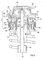
- a device for height adjustment of the structure of a motor vehicle with a rotationally symmetrical Adjustment unit 10, the body side between a spring dome 12 and a helical compression spring or suspension spring 14 on the other hand is turned on.
- a telescopic shock absorber 16 is shown partially positioned, which has a cylinder tube 18 and a piston rod 20 in a known manner.
- the piston rod 20 is articulated via an unspecified, known per se damper bearing 22 with a support plate 24 on the spring dome 12 and the structure of the motor vehicle.
- Damper bearing 22 extends around the piston rod head as an annular elastomeric block.
- the piston rod head is supported in a customary manner on a metal disc 23 integrated in the elastomer block and secured thereto by means of a screw connection.
- a spacer tube 26 is integrally formed on the piston rod 20 around a rubber-elastic stop buffer 28 is supported.
- the stop buffer 28 acts in a manner to be described with the adjacent end face of the cylinder tube 18 of the shock absorber 16 as an additional spring for the progressive increase of the spring rate of the suspension spring 14 together.
- the cylinder tube 18 of the shock absorber 16 is either articulated to a wheel guide element (eg a handlebar) of the wheel suspension of the motor vehicle or fixedly connected to a wheel guide element (eg a wheel carrier) as a wheel-guiding shock absorber.
- a wheel guide element eg a handlebar
- a wheel guide element eg a wheel carrier
- the adjusting unit 10 for height adjustment of the body 12 of the motor vehicle is composed essentially of a base plate 30, an integrally formed on the base plate 30 inner cylinder 32, a first actuating piston 34th and a second actuating piston 36, both of which are guided axially displaceably on the inner cylinder 32, furthermore an outer cylinder 38 fixedly connected to the base plate 30 and an outer cylinder 40 formed on the first actuating piston 34.
- the base plate 30 is fastened together with the support plate 24 by means of screws 25 bolted to the spring dome 12 and the structure.
- the guided on the outer cylinder 38 and the inner cylinder 32 actuator piston 34 defines a first, annular hydraulic chamber 42 (see. Fig. 1 ), which is connected via incorporated into the base plate 30 channels 44 with a first pressure line 46 of an electro-hydraulic control unit 48 to be described later.
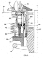
- the smaller in outer diameter, second control piston 36 (see. Fig. 2 ) is axially slidably guided on the outer cylinder 40 and also the inner cylinder 32 and limited in connection with the first actuating piston 34, a second, annular hydraulic chamber 50, which is incorporated predominantly by an annular recess 52 in the second control piston 36.
- the hydraulic connection to a likewise connected to the base plate 30, the second pressure line 54 of the control unit 48 ( Fig. 7
- the pressure tube 58 is fixed (eg, screwed in) to the base plate 30, passes through the first hydraulic chamber 42 as shown, and protrudes through a sliding guide Hole 34 a of the first actuating piston 34 into the second hydraulic chamber 50 into it.
- the rigid pressure tube 58 is sealed in the bore 34a by means of a sealing ring 60.
- the recess 52 in the adjusting piston 36 is designed so deep that the pressure tube 58 can freely dive into the recess 52 with retracted adjusting piston 34 and 36.
- the spring plate 62 is formed directly on its underside, on which the suspension spring 14 is supported with the interposition of a rubber-elastic spring pad 64.
- the suspension spring 14 on the other hand on the cylinder tube 18 of the shock absorber 16 supporting spring plate is not shown.
- the spring force of the bearing supported on the spring plate 62 suspension spring 14 is therefore passed over the control piston 34, 36 and the base plate 30 of the adjusting unit 10 past the damper bearing 22 directly into the vehicle body.
- the damper bearing 22 is therefore free of spring forces of the suspension spring 14, so that it is advantageous to interpret only the inclusion of damper forces, which are introduced via the piston rod 20 of the shock absorber 16.
- the hydraulic chambers 42, 50 are designed to be liquid-tight or that, as shown, corresponding ring seals (without reference numerals) are provided on the adjusting pistons 34, 36 and on the base plate 30. Furthermore, on the outer cylinder 38 and on the inner cylinder 32, annular stops 38a, 32a (FIG. Fig. 1 ) are provided, on which the adjusting pistons 34, 36 can strike in their extended position and thus define level positions. In the retracted positions, the adjusting piston 34 engages the base plate 30 and the adjusting piston 36 to the adjusting piston 34 as shown. Furthermore, a protective sleeve 66 is attached to the outer cylinder 38 and to the spring plate 62, which counteracts penetration of dirt or moisture into the adjustment unit 10.
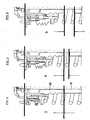
- the adjusting unit 10 allows a height adjustment of the structure or spring dome 12 in the high level (both actuating pistons 34, 36 extended), normal level (actuator piston 34 extended, actuating piston 36 retracted) and low level (both control pistons 34, 36 depressurized or retracted).
- the level positions low level, normal level and high level of the adjustment unit 10 are in the 4 to 6 each shown individually. Consequently, the stop buffer 28 is in accordance with Fig. 4 designed in terms of height so that it strikes more or less at the low level position on the front side of the cylinder tube 18 of the shock absorber 16 and thus increases the spring rate of the suspension spring 14 progressively as an additional spring inserting.
- a distance between the stop buffer 28 and the cylinder tube 18 is 0 here.
- FIGS. 5 and 6 the structure is shown in each case in the normal level and high level in the level position, in which the distance between the cylinder tube 18 and the stop buffer 28 is at a or b.
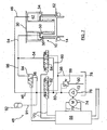
- the control unit 48 has an electronic control unit 68, the u. a. via electric lines (indicated generally by 70) an electric motor 74 which drives a hydraulic pump 72 when needed, and the control valves of the control unit 48 to be described, depending on the level position to be set.
- the hydraulic pump 72 draws in via a line 76 hydraulic fluid from a reservoir or hydraulic sump 78 and conveys them via flow lines 80 to two 4/3 way valves 82, 84. Furthermore, from the directional control valves 82, 84 return lines 86, which in the hydraulic sump 78th lead. In the flow line 80, a pressure relief valve 88 is also connected to a further return line 90.
- directional control valves 82, 84 further go from the pressure lines 46, 54, which communicate with the hydraulic chambers 42, 50 of the adjusting unit 10 as described above.
- a pressure accumulator 92 (accumulator) is connected to the pressure line 46 via a line 91 with a defined storage volume.
- the accumulator 92 can be connected via a 4/2 way valve 94 and a connecting line 96 and the pressure line 54.
- the applied accumulator pressure of the pressure accumulator 92 is monitored in a manner not shown via the electronic control unit 68.
- the directional control valves 82, 84 can be controlled by the electronic control unit 68 in the three positions pressurization, pressure maintenance and pressure relief.
- the supply lines 80 are connected to the pressure line 46 or to both pressure lines 46, 54 when the hydraulic pump 72 is activated.
- the directional control valve 94 is closed or the connecting line 96 is interrupted, when pressure is applied to both pressure lines 46, 54, the directional control valve 94 is opened.
- the control unit 68 switches the directional control valves 82, 84 to pressure maintenance, wherein the pressure lines 46 or 46, 54 are separated from the flow lines 80.
- control unit 68 controls the directional control valve 84 so that this the pressure line 54 connects to the return line 86.
- the directional control valve 94 is closed, whereby the pressure line 46 remains pressurized and the pressure line 54 is depressurized.
- the pressure line 46 is finally connected via the directional control valve 82 to the return line 86, so that the first adjusting piston 34 also retracts when the hydraulic chamber 42 is emptied.
Landscapes
- Engineering & Computer Science (AREA)
- Mechanical Engineering (AREA)
- Vehicle Body Suspensions (AREA)
- Fluid-Damping Devices (AREA)
Claims (12)
- Dispositif pour le réglage en hauteur de la carrosserie (12) de véhicules automobiles par rapport à la suspension de roue, avec une unité de réglage (10) actionnée par des moyens hydrauliques, laquelle est placée entre la carrosserie (12) et la coupelle de ressort (62) d'un ressort de suspension (14) de la suspension de roue et qui comporte au moins deux pistons de réglage (34, 36) qui sont guidés en translation dans des cylindres (38, 40), qui sont agencés l'un derrière l'autre de manière télescopique, qui peuvent être alimentés en pression séparément ou ensemble par l'intermédiaire d'une unité de commande électrohydraulique et qui règlent en hauteur la carrosserie (12), l'alimentation en pression des deux chambres hydrauliques (42, 50) des pistons de réglage (34, 36) réglables séparément s'effectuant à partir d'une plaque de base (30) qui est placée du côté de la carrosserie et qui délimite la première chambre hydraulique (42), caractérisé en ce que les deux pistons de réglage (34, 36) sont réalisés en forme d'anneau et en ce que la plaque de base (30) est conçue avec un cylindre intérieur (32) sur lequel les deux pistons de réglage (34, 36) sont guidés ensemble en translation.
- Dispositif selon la revendication 1, caractérisé en ce que, sur la plaque de base (30), est agencé un élément tubulaire (58) qui traverse la première chambre hydraulique (42) et qui débouche, à travers le premier piston de réglage (34), dans la deuxième chambre hydraulique (50).
- Dispositif selon l'une des revendications 1 ou 2, caractérisé en ce que l'élément tubulaire (58) est fixé à la plaque de base (30) et est guidé de façon étanche dans le premier piston de réglage (34).
- Dispositif selon l'une des revendications 1 à 3, caractérisé en ce que, lorsque le premier et le deuxième piston de réglage (34, 36) sont rentrés, l'élément tubulaire (58) pénètre dans un évidement (52) prévu dans le deuxième piston de réglage (36) et ouvert en direction de la deuxième chambre hydraulique (50).
- Dispositif selon l'une des revendications 1 à 4, caractérisé en ce que le premier piston de réglage (34) est guidé en plus dans un cylindre extérieur (38) fixé sur la plaque de base (30) et en ce qu'un deuxième cylindre extérieur (40), qui est inférieur en diamètre et dans lequel le deuxième piston de réglage (36) est guidé en translation, est formé sur le premier piston de réglage (34).
- Dispositif selon l'une des revendications 1 à 5, caractérisé en ce que la coupelle de ressort (62) est formée directement sur le deuxième piston de réglage (36).
- Dispositif selon l'une des revendications précédentes, caractérisé en ce qu'il est prévu entre la carrosserie (12) du véhicule automobile et un élément de suspension de roue (16) un tampon de butée (28) qui, de préférence pour une position de la carrosserie (12) correspondant au niveau bas, vient en contact avec l'élément de suspension de roue (16) et agit alors comme ressort supplémentaire.
- Dispositif selon la revendication 7, caractérisé en ce que, à l'intérieur du ressort de suspension (14) et de l'unité de réglage (10), il est prévu un amortisseur télescopique (16) dont la tige de piston (20) est reliée à la carrosserie (12) par l'intermédiaire d'un palier d'amortisseur (22) et d'une plaque d'appui (24) et en ce que le tampon de butée (28) est agencé à l'intérieur de l'unité de réglage (10) et coopère avec la plaque d'appui (24) et avec le tube cylindrique (18) de l'amortisseur (16).
- Dispositif selon la revendication 8, caractérisé en ce qu'une douille d'écartement (26) logeant le tampon de butée (28) et formée sur la plaque d'appui (24) est agencée entre la plaque d'appui (24) du palier d'amortisseur (22) et le tampon de butée (28).
- Dispositif selon l'une des revendications précédentes, comportant une unité de commande électrohydraulique (48) avec une source de fluide de pression (72), avec une conduite d'aller (80) conduisant la pression, avec une conduite de retour (86) reliée à un collecteur de fluide de pression (78) et avec au moins deux vannes de commande (82, 84) actionnées par électricité qui alimentent en fluide de pression en provenance de la conduite d'aller (80), en alternance ou simultanément, par l'intermédiaire de conduites de pression (46, 54), les chambres hydrauliques (42, 50) des pistons de réglage (34, 36) ou qui relient celles-ci à la conduite de retour (86), caractérisé en ce qu'un accumulateur de pression (92) est raccordé aux conduites de pression (46, 54) et en ce que les deux vannes de commande (82, 84) sont des vannes à 4/3 voies qui ont une fonction de maintien de la pression en plus de l'alimentation en pression et de la détente des chambres hydrauliques (42, 50).
- Dispositif selon la revendication 10, caractérisé en ce que l'accumulateur de pression (92) peut être branché sur les deux conduites de pression (46, 54) ou seulement sur l'une des deux au moyen d'une vanne à 4/2 voies (94) reliant ou séparant les deux conduites de pression (46, 54).
- Dispositif selon l'une des revendications 1 à 11, caractérisé en ce que les pistons de réglage (34, 36) sont réglables en hauteur dans les positions niveau bas, niveau normal ou niveau haut.
Applications Claiming Priority (1)
| Application Number | Priority Date | Filing Date | Title |
|---|---|---|---|
| DE200610026625 DE102006026625B4 (de) | 2006-06-08 | 2006-06-08 | Vorrichtung zur Höhenverstellung des Aufbaus von Kraftfahrzeugen |
Publications (3)
| Publication Number | Publication Date |
|---|---|
| EP1864836A2 EP1864836A2 (fr) | 2007-12-12 |
| EP1864836A3 EP1864836A3 (fr) | 2008-01-09 |
| EP1864836B1 true EP1864836B1 (fr) | 2014-06-25 |
Family
ID=38471858
Family Applications (1)
| Application Number | Title | Priority Date | Filing Date |
|---|---|---|---|
| EP07005425.9A Not-in-force EP1864836B1 (fr) | 2006-06-08 | 2007-03-16 | Dispositif destiné au réglage en hauteur du montage de véhicules automobiles |
Country Status (2)
| Country | Link |
|---|---|
| EP (1) | EP1864836B1 (fr) |
| DE (1) | DE102006026625B4 (fr) |
Cited By (2)
| Publication number | Priority date | Publication date | Assignee | Title |
|---|---|---|---|---|
| CN104442265A (zh) * | 2014-12-09 | 2015-03-25 | 山东交通学院 | 一种基于液压作动筒调节的运输车辆主动防侧翻控制系统 |
| FR3139033A1 (fr) | 2022-08-30 | 2024-03-01 | Psa Automobiles Sa | Coupelle de compression d’un amortisseur de véhicule automobile |
Families Citing this family (10)
| Publication number | Priority date | Publication date | Assignee | Title |
|---|---|---|---|---|
| EP2119580A1 (fr) * | 2008-05-15 | 2009-11-18 | Paioli S.p.A. | Amortisseur de chocs pour véhicules, particulièrement pour véhicules de type moto et similaires |
| DE102008023891A1 (de) * | 2008-05-16 | 2009-11-19 | Audi Ag | Vorrichtung zur Höhenverstellung der Karosserie eines Kraftfahrzeuges |
| DE102009018439A1 (de) * | 2009-04-22 | 2010-10-28 | Audi Ag | Vorrichtung zum Abstützen einer Tragfeder einer Radaufhängung für ein Kraftfahrzeug sowie Verfahren zum Einbau einer solchen Vorrichtung |
| DE102009057003A1 (de) * | 2009-12-04 | 2011-06-09 | Audi Ag | Federbeinanordnung für eine Radaufhängung eines Kraftfahrzeuges |
| ITTO20100695A1 (it) * | 2010-08-13 | 2012-02-14 | Sistemi Sospensioni Spa | Sospensione per veicolo comprendente un dispositivo di regolazione dell'altezza del corpo del veicolo da terra |
| DE102011079714A1 (de) * | 2011-07-25 | 2013-01-31 | Klaus Wohlfahrt | Höhenverstelleinrichtung |
| FR3060465B1 (fr) * | 2016-12-21 | 2019-08-23 | Renault S.A.S | Systeme de suspension et d'amortissement adapte pour le reglage de garde au sol d'un vehicule automobile |
| DE102018205223A1 (de) | 2018-04-06 | 2019-10-10 | Zf Friedrichshafen Ag | Verstellbarer Federträger |
| DE102018214041A1 (de) * | 2018-08-21 | 2020-02-27 | Bayerische Motoren Werke Aktiengesellschaft | Höhenverstellbares Feder-Dämpfersystem für ein Fahrzeug |
| DE102019208585A1 (de) * | 2019-06-13 | 2020-12-17 | Audi Ag | Vorrichtung zur Höhenverstellung eines Fahrzeugaufbaus |
Citations (1)
| Publication number | Priority date | Publication date | Assignee | Title |
|---|---|---|---|---|
| JP2000352436A (ja) * | 1999-06-14 | 2000-12-19 | Kayaba Ind Co Ltd | ばね力調整装置 |
Family Cites Families (15)
| Publication number | Priority date | Publication date | Assignee | Title |
|---|---|---|---|---|
| JPS58136506A (ja) * | 1982-02-09 | 1983-08-13 | Showa Mfg Co Ltd | 車高調整装置 |
| DE3223263C2 (de) * | 1982-06-22 | 1986-03-20 | Mannesmann Rexroth GmbH, 8770 Lohr | Einrichtung zur Niveauregelung eines Kraftfahrzeuges |
| DE3324270C2 (de) * | 1983-07-06 | 1986-08-07 | Montanhydraulik GmbH, 4755 Holzwickede | Teleskopierzylinder-System |
| DE3502579A1 (de) * | 1985-01-26 | 1986-07-31 | Audi Nsu Auto Union Ag, 7107 Neckarsulm | Hoehenverstellvorrichtung |
| JPS62231810A (ja) * | 1986-03-31 | 1987-10-12 | Aisin Seiki Co Ltd | 車高調整装置用のジヤツキ装置 |
| JPS62292514A (ja) * | 1986-06-12 | 1987-12-19 | Aisin Seiki Co Ltd | 流体圧利用の伸縮装置 |
| DE19606991C2 (de) * | 1996-02-24 | 1998-11-12 | Daimler Benz Ag | Feder-Schwingungsdämpfer-Einrichtung eines Kraftfahrzeuges |
| JP3832779B2 (ja) | 1996-12-19 | 2006-10-11 | カヤバ工業株式会社 | 車高調整装置および車高調整システム |
| JP3650243B2 (ja) * | 1997-01-31 | 2005-05-18 | カヤバ工業株式会社 | 車高調整装置および車高調整システム |
| JPH10217737A (ja) * | 1997-02-07 | 1998-08-18 | Kayaba Ind Co Ltd | 車高調整装置および車高調整システム |
| JP3695729B2 (ja) | 1997-03-07 | 2005-09-14 | カヤバ工業株式会社 | 車高調整システム |
| DE10153007A1 (de) * | 2001-10-26 | 2003-05-08 | Audi Ag | Vorrichtung zur Höhenverstellung |
| JP2003205722A (ja) * | 2002-01-15 | 2003-07-22 | Masaaki Aoki | 車高調整装置およびこれを用いた自動車 |
| JP2004181995A (ja) * | 2002-11-29 | 2004-07-02 | Atsushi Sakamoto | アッパーマウント |
| JP2006088962A (ja) * | 2004-09-27 | 2006-04-06 | Toyota Motor Corp | ストラット式サスペンション |
-
2006
- 2006-06-08 DE DE200610026625 patent/DE102006026625B4/de not_active Expired - Fee Related
-
2007
- 2007-03-16 EP EP07005425.9A patent/EP1864836B1/fr not_active Not-in-force
Patent Citations (1)
| Publication number | Priority date | Publication date | Assignee | Title |
|---|---|---|---|---|
| JP2000352436A (ja) * | 1999-06-14 | 2000-12-19 | Kayaba Ind Co Ltd | ばね力調整装置 |
Cited By (2)
| Publication number | Priority date | Publication date | Assignee | Title |
|---|---|---|---|---|
| CN104442265A (zh) * | 2014-12-09 | 2015-03-25 | 山东交通学院 | 一种基于液压作动筒调节的运输车辆主动防侧翻控制系统 |
| FR3139033A1 (fr) | 2022-08-30 | 2024-03-01 | Psa Automobiles Sa | Coupelle de compression d’un amortisseur de véhicule automobile |
Also Published As
| Publication number | Publication date |
|---|---|
| DE102006026625B4 (de) | 2008-11-13 |
| EP1864836A2 (fr) | 2007-12-12 |
| EP1864836A3 (fr) | 2008-01-09 |
| DE102006026625A1 (de) | 2007-12-13 |
Similar Documents
| Publication | Publication Date | Title |
|---|---|---|
| EP1864836A2 (fr) | Dispositif destiné au réglage en hauteur du montage de véhicules automobiles | |
| DE102012214569B3 (de) | Luftfeder- und Dämpfereinheit mit Höhenverstellung | |
| DE3902743C1 (en) | Active wheel or axle support | |
| DE102008006476B4 (de) | Gasdruckstoßdämpfer | |
| DE102004032083B4 (de) | Feder- und Dämpfungsvorrichtung für Radaufhängungen | |
| DE10019532A1 (de) | Federungssystem für Kraftfahrzeuge | |
| DE1505522B1 (de) | Hydropneumatischer Einrohr-Teleskopstossdaempfer mit davon unabhaengiger,parallel geschalteter Gasfeder und selbsttaetig steuerbarem Daempfungsgrad,insbesondere fuer Kraftfahrzeuge | |
| DE19857595A1 (de) | Selbstpumpendes hydropneumatisches Federbein mit innerer Niveauregelung | |
| DE3806709A1 (de) | Federbein fuer fahrzeuge | |
| DE102005059117A1 (de) | Aktuator für ein aktives Fahrwerk eines Kraftfahrzeugs | |
| DE102015016024A1 (de) | Federsystem eines Schienenfahrzeuges | |
| WO2020001962A1 (fr) | Suspension de roue de véhicule avec un système de positionnement pour le pied d'un ressort porteur de carrosserie | |
| EP3840966B1 (fr) | Système d'amortisseur à ressort réglable en hauteur conçu pour un véhicule | |
| DE19731139C2 (de) | Kolben-Zylinder-Aggregat, das zwischen einem Aufbau und einem Radführungsteil eines Fahrzeugs eingebaut ist | |
| WO2017081090A1 (fr) | Châssis de véhicule automobile | |
| DE19632805A1 (de) | Vorrichtung zur höhenveränderlichen Abstützung einer Rad- oder Achsfederung am Aufbau eines Kraftfahrzeugs | |
| EP3519286B1 (fr) | Motocyclette avec dispositif fluide pour baisser | |
| DE102008017702B4 (de) | Achshebevorrichtung und Verfahren zum Anheben einer Achse | |
| WO2011147613A2 (fr) | Jambe de force à autopompage | |
| WO2007033718A1 (fr) | Ensemble stabilisateur d'un vehicule automobile | |
| DE3606961A1 (de) | Radaufhaengung | |
| DE102004045011B4 (de) | Kolbenzylindereinheit | |
| EP1477343B1 (fr) | Système de suspension pour véhicule avec hauteur de châssis variable | |
| EP1403103B1 (fr) | Jambe de suspension réglable pour véhicules automobiles | |
| DE10306157B4 (de) | Fahrzeug-Federung mit veränderbarem Höhenstand des Fahrzeug-Aufbaus |
Legal Events
| Date | Code | Title | Description |
|---|---|---|---|
| PUAI | Public reference made under article 153(3) epc to a published international application that has entered the european phase |
Free format text: ORIGINAL CODE: 0009012 |
|
| PUAL | Search report despatched |
Free format text: ORIGINAL CODE: 0009013 |
|
| AK | Designated contracting states |
Kind code of ref document: A2 Designated state(s): AT BE BG CH CY CZ DE DK EE ES FI FR GB GR HU IE IS IT LI LT LU LV MC MT NL PL PT RO SE SI SK TR |
|
| AX | Request for extension of the european patent |
Extension state: AL BA HR MK YU |
|
| AK | Designated contracting states |
Kind code of ref document: A3 Designated state(s): AT BE BG CH CY CZ DE DK EE ES FI FR GB GR HU IE IS IT LI LT LU LV MC MT NL PL PT RO SE SI SK TR |
|
| AX | Request for extension of the european patent |
Extension state: AL BA HR MK YU |
|
| 17P | Request for examination filed |
Effective date: 20080709 |
|
| AKX | Designation fees paid |
Designated state(s): DE FR GB IT |
|
| 17Q | First examination report despatched |
Effective date: 20080902 |
|
| GRAJ | Information related to disapproval of communication of intention to grant by the applicant or resumption of examination proceedings by the epo deleted |
Free format text: ORIGINAL CODE: EPIDOSDIGR1 |
|
| GRAP | Despatch of communication of intention to grant a patent |
Free format text: ORIGINAL CODE: EPIDOSNIGR1 |
|
| GRAP | Despatch of communication of intention to grant a patent |
Free format text: ORIGINAL CODE: EPIDOSNIGR1 |
|
| INTG | Intention to grant announced |
Effective date: 20140401 |
|
| INTG | Intention to grant announced |
Effective date: 20140410 |
|
| GRAS | Grant fee paid |
Free format text: ORIGINAL CODE: EPIDOSNIGR3 |
|
| GRAA | (expected) grant |
Free format text: ORIGINAL CODE: 0009210 |
|
| AK | Designated contracting states |
Kind code of ref document: B1 Designated state(s): DE FR GB IT |
|
| REG | Reference to a national code |
Ref country code: GB Ref legal event code: FG4D Free format text: NOT ENGLISH |
|
| REG | Reference to a national code |
Ref country code: DE Ref legal event code: R096 Ref document number: 502007013221 Country of ref document: DE Effective date: 20140731 |
|
| REG | Reference to a national code |
Ref country code: DE Ref legal event code: R084 Ref document number: 502007013221 Country of ref document: DE |
|
| REG | Reference to a national code |
Ref country code: DE Ref legal event code: R084 Ref document number: 502007013221 Country of ref document: DE Effective date: 20141219 |
|
| REG | Reference to a national code |
Ref country code: FR Ref legal event code: PLFP Year of fee payment: 9 |
|
| REG | Reference to a national code |
Ref country code: DE Ref legal event code: R097 Ref document number: 502007013221 Country of ref document: DE |
|
| PG25 | Lapsed in a contracting state [announced via postgrant information from national office to epo] |
Ref country code: IT Free format text: LAPSE BECAUSE OF FAILURE TO SUBMIT A TRANSLATION OF THE DESCRIPTION OR TO PAY THE FEE WITHIN THE PRESCRIBED TIME-LIMIT Effective date: 20140625 |
|
| PLBE | No opposition filed within time limit |
Free format text: ORIGINAL CODE: 0009261 |
|
| STAA | Information on the status of an ep patent application or granted ep patent |
Free format text: STATUS: NO OPPOSITION FILED WITHIN TIME LIMIT |
|
| PGFP | Annual fee paid to national office [announced via postgrant information from national office to epo] |
Ref country code: FR Payment date: 20150319 Year of fee payment: 9 Ref country code: GB Payment date: 20150319 Year of fee payment: 9 |
|
| 26N | No opposition filed |
Effective date: 20150326 |
|
| PGFP | Annual fee paid to national office [announced via postgrant information from national office to epo] |
Ref country code: DE Payment date: 20150331 Year of fee payment: 9 |
|
| REG | Reference to a national code |
Ref country code: DE Ref legal event code: R119 Ref document number: 502007013221 Country of ref document: DE |
|
| GBPC | Gb: european patent ceased through non-payment of renewal fee |
Effective date: 20160316 |
|
| REG | Reference to a national code |
Ref country code: FR Ref legal event code: ST Effective date: 20161130 |
|
| PG25 | Lapsed in a contracting state [announced via postgrant information from national office to epo] |
Ref country code: GB Free format text: LAPSE BECAUSE OF NON-PAYMENT OF DUE FEES Effective date: 20160316 Ref country code: FR Free format text: LAPSE BECAUSE OF NON-PAYMENT OF DUE FEES Effective date: 20160331 Ref country code: DE Free format text: LAPSE BECAUSE OF NON-PAYMENT OF DUE FEES Effective date: 20161001 |