EP1865136A2 - Schließmechanismus für eine Schiebetür - Google Patents
Schließmechanismus für eine Schiebetür Download PDFInfo
- Publication number
- EP1865136A2 EP1865136A2 EP07010937A EP07010937A EP1865136A2 EP 1865136 A2 EP1865136 A2 EP 1865136A2 EP 07010937 A EP07010937 A EP 07010937A EP 07010937 A EP07010937 A EP 07010937A EP 1865136 A2 EP1865136 A2 EP 1865136A2
- Authority
- EP
- European Patent Office
- Prior art keywords
- cable
- door
- base
- plunger
- closer
- Prior art date
- Legal status (The legal status is an assumption and is not a legal conclusion. Google has not performed a legal analysis and makes no representation as to the accuracy of the status listed.)
- Withdrawn
Links
- 230000007246 mechanism Effects 0.000 title claims abstract description 67
- 230000002093 peripheral effect Effects 0.000 claims description 6
- 230000000994 depressogenic effect Effects 0.000 claims description 5
- 230000000295 complement effect Effects 0.000 claims 3
- 239000011521 glass Substances 0.000 description 6
- 239000000853 adhesive Substances 0.000 description 2
- 230000001070 adhesive effect Effects 0.000 description 2
- 241000272184 Falconiformes Species 0.000 description 1
- 241000238631 Hexapoda Species 0.000 description 1
- XAGFODPZIPBFFR-UHFFFAOYSA-N aluminium Chemical compound [Al] XAGFODPZIPBFFR-UHFFFAOYSA-N 0.000 description 1
- 229910052782 aluminium Inorganic materials 0.000 description 1
- 235000013305 food Nutrition 0.000 description 1
- 235000015220 hamburgers Nutrition 0.000 description 1
- 238000002347 injection Methods 0.000 description 1
- 239000007924 injection Substances 0.000 description 1
- 238000009434 installation Methods 0.000 description 1
- 239000000463 material Substances 0.000 description 1
- 238000000034 method Methods 0.000 description 1
- 229920003023 plastic Polymers 0.000 description 1
- 229920000915 polyvinyl chloride Polymers 0.000 description 1
- 230000000284 resting effect Effects 0.000 description 1
- 239000002023 wood Substances 0.000 description 1
Images








Classifications
-
- E—FIXED CONSTRUCTIONS
- E05—LOCKS; KEYS; WINDOW OR DOOR FITTINGS; SAFES
- E05F—DEVICES FOR MOVING WINGS INTO OPEN OR CLOSED POSITION; CHECKS FOR WINGS; WING FITTINGS NOT OTHERWISE PROVIDED FOR, CONCERNED WITH THE FUNCTIONING OF THE WING
- E05F1/00—Closers or openers for wings, not otherwise provided for in this subclass
- E05F1/08—Closers or openers for wings, not otherwise provided for in this subclass spring-actuated, e.g. for horizontally sliding wings
- E05F1/16—Closers or openers for wings, not otherwise provided for in this subclass spring-actuated, e.g. for horizontally sliding wings for sliding wings
-
- E—FIXED CONSTRUCTIONS
- E05—LOCKS; KEYS; WINDOW OR DOOR FITTINGS; SAFES
- E05F—DEVICES FOR MOVING WINGS INTO OPEN OR CLOSED POSITION; CHECKS FOR WINGS; WING FITTINGS NOT OTHERWISE PROVIDED FOR, CONCERNED WITH THE FUNCTIONING OF THE WING
- E05F3/00—Closers or openers with braking devices, e.g. checks; Construction of pneumatic or liquid braking devices
- E05F3/22—Additional arrangements for closers, e.g. for holding the wing in opened or other position
- E05F3/227—Additional arrangements for closers, e.g. for holding the wing in opened or other position mounted at the top of wings, e.g. details related to closer housings, covers, end caps or rails therefor
-
- E—FIXED CONSTRUCTIONS
- E05—LOCKS; KEYS; WINDOW OR DOOR FITTINGS; SAFES
- E05Y—INDEXING SCHEME ASSOCIATED WITH SUBCLASSES E05D AND E05F, RELATING TO CONSTRUCTION ELEMENTS, ELECTRIC CONTROL, POWER SUPPLY, POWER SIGNAL OR TRANSMISSION, USER INTERFACES, MOUNTING OR COUPLING, DETAILS, ACCESSORIES, AUXILIARY OPERATIONS NOT OTHERWISE PROVIDED FOR, APPLICATION THEREOF
- E05Y2900/00—Application of doors, windows, wings or fittings thereof
- E05Y2900/10—Application of doors, windows, wings or fittings thereof for buildings or parts thereof
- E05Y2900/13—Type of wing
- E05Y2900/132—Doors
Definitions
- This invention generally relates to sliding doors. More particularly, the invention relates to a closer mechanism for sliding glass doors and sliding screens. Specifically, the invention relates to an automatic closer mechanism for a sliding door that comprises a spring-tensioned block and tackle mechanism and includes a lock for selectively disabling the closer to allow for manual operation of the door.
- the frames for sliding-type glass doors with sliding screens are made from many different materials such as wood, aluminum and plastic. Each manufacturer makes different systems with different size doors and clearances between the sliding glass panels and the screen panels.
- the screen panels are very light and move easily, but the glass doors are much heavier and require more effort to move.
- sliding doors When sliding doors are opened they remain that way until the user physically closes them again. Unless the user pays attention, the door may not close all the way, thus allowing insects to fly into the house, heated or cooled air to escape from the building and provides a space through which younger children may exit the building or can use to slide a screen, for instance, out of the way to exit the building.
- U.S. Patent Number 4,126,912 to Johnson ; 4,357,732 to Hickman ; 4,891,011 to Yung and 4,884,369 to Tatham include gravity- activated mechanisms for closing a sliding door.
- Other patents, such as 4,003,102 to Hawks et al having included pneumatic cylinders for achieving the same end.
- Still others, such as 4,004,372 have included coils springs and dampeners for achieving this end.
- U.S. Patent Numbers 5,131,188 to Hutchison et al ; 4,819,925 to Kaftan and 4,301,623 to Demukai have included block and tackle mechanisms for closing sliding doors.
- the device of the present invention is an automatic door closer for sliding doors. Lighter weight doors, such as screen doors, would have a smaller, lighter closer mechanism attached thereto and heavier sliding doors such as glass doors would have a larger, heavier duty closer mechanism attached thereto.
- the automatic door closer comprises a base which is mounted to the exterior of one of a sliding door and a door frame.
- the base includes a block and tackle mechanism where the block slides along the base between two end caps.
- a cable extends outwardly from the base and is attached to the other of the sliding door and door frame.
- the base is mounted on a surface by one of screws, rivets, two-sided tape or any other suitable fastening mechanism.
- One or more tension springs are connected at one end to the sliding block and to the other end to one of the end caps so as to bias the door into a closed position. When the door is opened, a length of cable is drawn out of the closer mechanism.
- the closer mechanism further includes a mechanism for locking the cable so that it cannot be drawn out of or into the base.
- a first embodiment of the locking mechanism comprises a cam lock that applies pressure to the cable and prevents it from moving until the cam lock is released.
- a second embodiment of the locking mechanism comprises a slide lock that includes a housing and a spring-biased plunger that is selectively depressed into the housing. When the plunger is in a depressed position the cable can slide freely through the slide lock, and when the plunger is in a released position the cable cannot slide through the slide lock. The slide lock is therefore positionable on the cable to stop the movement of the door at the slide lock's position.
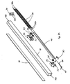
- FIG. 1 there is shown an automatic closer mechanism in accordance with the present invention and generally indicated at 10.
- Closer mechanism 10 is mounted on a sliding door 12 and is connected at a first end to the door frame 14. Closer mechanism 10 allows door 12 to be opened and then when released by the user, slides automatically back into a closed position.
- closer mechanism 10 includes a base 16 which is mounted onto door 12 by way of a suitable connector such as two-sided tape 18.
- Base 16 is an elongated member that is substantially rectangular in cross-section and includes an internal bore 20 therethrough.
- Injection molded end caps 22 and 24 are mounted one at each end of base 16, with end cap 22 being disposed proximate a first end 16a of base 16 and end cap 24 being disposed proximate the second end 16b thereof.
- a fastener (not shown) may be inserted through a hole 31 in a tab 33 on end cap 22 to secure end cap 22 to door 12.
- a second fastener (not shown) may be inserted through a hole 27 in a tab 25 on end cap 24 to secure that end cap to door 12.
- a slidable block 36 is disposed within the bore 20 in base 16 and intermediate end caps 22 and 24.
- a first pulley 26 is provided on end cap 22 and a second set of pulleys, 32, 34 is provided upon block 36.
- Cable 44 is attached to either one of end cap 22 and block 36 at a first end. Cable 44 is then threaded around pulleys 26, 32, 34; through an aperture 35 in end cap 22 and attached at a second end by a fastener to door frame 14.
- a suitable fastener is an L-shaped frame member 46 (Fig. 3) that is received around a portion of frame 14 or a pin 47 (Fig.
- FIG. 3A which is screwed into frame 14 or is inserted into a pre-drilled hole therein.
- End cap 24 is also provided with an aperture 42 therein.
- One or more coil springs 38 extend between block 36 and end cap 24, with a first end of each spring 38a being hooked through an aperture 40 in block 36 and a second end 38b of each spring 38 being hooked through aperture 42 in end cap 24. Springs 38 bias door 12 into a closed position.
- Base 16 and end caps 22, 24 preferably are manufactured from an extruded vinyl plastic.
- Spring 38 keeps the end caps 22 and 24 drawn toward each other and thereby holds closer mechanism 10 together.
- Block 36 reciprocates between end caps 22 and 24 in response to the opening and closing of door 12.
- Closer mechanism 10 consequently comprises a block and tackle type of arrangement mounted within base 16.
- Locking mechanism 30 preferably comprises a cam lock 30 which is mounted on end cap 22 proximate pulley 26 (Figs. 3, 4, 8 &9).
- Cam lock 30 includes a first part 30a mounted on end cap 22 proximate pulley 26 and a second part 30b which projects outwardly from first part 30a and through aperture 35 in end cap 22.
- Second part 30b is flanged so that it may be more easily engaged by the user.
- Cable 44 is threaded through aperture 35 and is disposed between second part 30b and a part of the interior surface 37 of the end cap 22 surrounding aperture 35.
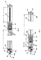
- Fig. 6 illustrates the resting position of closer 10
- Fig. 7 illustrates the tensioned position of closer 10.
- Cam lock 30 is shown in both Figs. 6 & 7 in a locked position.
- block 36 is spaced a first distance "A" from end cap 22 and spring has a length "B".
- Fig. 1 When door 12 is drawn open in the direction of arrow "C” (Fig. 1), block 36 slides along tracks 20a, 20b toward end cap 22. This shortens the distance between end cap 22 and block 36 to the length "D" (Fig.
- cam lock 30 may be engaged when the door is opened to the desired extent.
- the user merely pushes upwardly on second part 30b of cam lock 30 as indicated by arrow "X". This upward movement causes first part 30a of cam lock 30 to rotate in end cap 22, thereby causing a cam 43 to slide into a recess 37 and thereby wedging cable 44 between cam 43 and the interior surface of the recessed area (Fig. 9).
- cam lock 30 When the user wishes to allow door 12 to close completely, cam lock 30 is disengaged by rotating second part 30b downwardly in the direction of arrow "Y", causing cam 43 to slide out of recess 37 and out of engagement with cable 44. Cable 44 can then be once again drawn inwardly through aperture 35 as block 36 slides on base 16. This movement continues until the leading edge 12a of door 12 engages vertical upright 14a of frame 14 (Fig. 1).
- Figs. 10-12 illustrate a second manner in which the automatic closer mechanism can be mounted.
- the closer mechanism generally indicated at 110 is mounted on the vertical upright 114a of door frame 114. Closer 110 is mounted so that the cable 144 extends horizontally out of end cap 122 and is connected at its free end to the top of door 112.
- a length of cable 144a is drawn out of closer mechanism 110 and spring 138 is expanded in length.
- spring 138 When door 112 is released, spring 138 reverts back to its original length thereby causing block 136 to slide along base 116 and drawing length 144a of cable 144 back through end cap 122, through the plurality of pulleys, including pulley 134, and thereby drawing door 112 back toward vertical upright 114a.
- Closer mechanism 210 includes the basic components found in closer mechanism 10, including end caps 222, 224 mounted on a base 216, a slidable block 236 and a plurality of pulleys 226, 232 and 234 around which a cable 244 is threaded.
- One or more springs 238 connect sliding block 236 and end cap 224.
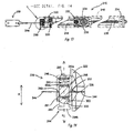
- Locking mechanism 230 is a slide lock that comprises a cylindrical shaped housing 290 having a peripheral wall 291 that has an axial bore 292 therein. Housing 290 further includes a pair of aligned holes 293 in its peripheral wall 291. A generally cylindrical plunger 294 is received within bore 292 and a spring 296 is disposed between the upper end wall 294a of plunger 294 and the inner wall 290a of housing 290. Plunger 294 further has an exterior wall 295 that extends between upper end wall 294a and lower end wall 294b.
- Upper end wall 294a of plunger 294 includes an annular lip 298 that extends outwardly beyond the exterior wall 295.
- Lower end wall 294b of plunger 294 also extends outwardly beyond exterior wall 295.
- Housing 290 further includes an in-turned flange 300 at the entrance to bore 292.
- Flange 300 is sized so that neither the upper end wall 294a nor lower wall 294b can pass through the entrance to bore 292.
- Plunger 294 is able to slide in bore 292 between flange 300 and inner wall 290 as is indicated by the arrow "R" in Fig. 14.
- Plunger 294 further includes a slot 302 that extends through exterior wall 291 substantially parallel to upper and lower end walls 294a, 294b and substantially at right angles to the longitudinal axis "Z" of housing 290.
- Cable 244 is threaded through holes 293 and slot 302.
- plunger 294 When plunger 294 is depressed inwardly into housing 290 and toward inner surface 290a, spring 296 becomes compressed between upper wall 294a and inner wall 290a. This movement also brings slot 302 into alignment with holes 293 in housing 290 and with aperture 235 in end cap 222. In this position, cable 244 can slide freely through locking mechanism 239 and locking mechanism 239 can therefore slide freely along cable 244 and can be moved closer to or further away from end cap 222.
- plunger 294 When plunger 294 is released, spring 296 reverts to its original shape and position, thereby urging plunger 294 away from inner surface 290a of housing 290. This causes slot 302 to move out of alignment with holes 293 and, consequently, cable 244 cannot feed through holes 293 and slot 302 and locking mechanism 230 becomes locked into place on cable 244.
- Locking mechanism 230 is designed to be slid along cable 244 and to be positioned at some location between fastener 246 and end cap 222. Locking mechanism 230 is therefore used in the following manner. If the homeowner wishes to have the door 212 automatically slide closed from a completely open position to a completely closed position, where door 212 abuts side frame 214a, then locking mechanism 230 is slid along cable 244 until it is positioned proximate fastener 246. If the homeowner wishes to keep the door 212 in a partially open position (such as is illustrated in Fig. 1), then locking mechanism 230 is slid along cable 244 until it is positioned a spaced distance away from side frame 214a.
- door 212 if door 212 is slid to the fully open position and then released, the closer mechanism 210 will automatically slide door 212 closed until end cap 222 encounters locking mechanism 230 on cable 244. Door 212 will stop at that position. Door 212 can be opened wider, but cannot be closed completely unless locking mechanism is slid back toward fastener 246. If the homeowner wishes to have the door 212 remain fully opened, then door 212 is opened to that extent and locking mechanism 230 is slid along cable 244 until it abuts end cap 222. This substantially prevents any closing movement of door 212 until locking mechanism 230 is slid along cable 244 toward fastener 246.
- Figs. 15-18 illustrate another embodiment of a fastener 246 that is designed to be applied to a corner 215 (Fig. 17) of a door frame 214.
- Fastener 246 comprises a plate 248 and a cover 250 that engage each other.
- Plate 248 is designed to be positioned on a corner 215 of door frame 214.
- Cable 244 is attached to cover 250 which, in turn, is engaged with plate 248.
- Plate 248 has a front surface 248a and rear surface 248b.
- Front surface 248a has a post 252 extending outwardly away therefrom.
- Rear surface 248b includes a V-shaped notch 254 that is shaped to receive corner 215 of frame 214 therein.
- An adhesive preferably is applied to rear surface 248b to secure plate 248 to frame 214.
- screws may be used to secure plate 248 to frame 214.
- cover 250 has a front surface 250a and a rear surface 250b.
- Rear surface 250b includes a V-shaped notch 256 that is shaped to receive the corner 258 (Fig. 17) of plate 248 therein.
- Cover 250 further includes an aperture 254 that is positioned and sized to receive post 252 therethrough.
- Cover 250 further includes a second aperture 256 through which cable 244 is received and secured.
- An adhesive may be applied to rear surface 250b of cover 250 to allow plate 248 and cover 250 to be secured together. Alternatively, screws (not shown) may be used to secure the two components together.
- base 16 may be formed as a two-part component instead of being formed as a substantially rectangular elongated member, In this former instance base will have a first part thereof mounted onto door 12 by tape 18 and a second part thereof being a snap-fitted cover that is received over the end caps, block and springs and which clips onto the first part of the base.
Landscapes
- Power-Operated Mechanisms For Wings (AREA)
Applications Claiming Priority (1)
| Application Number | Priority Date | Filing Date | Title |
|---|---|---|---|
| US11/450,037 US20070283524A1 (en) | 2006-06-08 | 2006-06-08 | Sliding door closer mechanism |
Publications (1)
| Publication Number | Publication Date |
|---|---|
| EP1865136A2 true EP1865136A2 (de) | 2007-12-12 |
Family
ID=38430469
Family Applications (1)
| Application Number | Title | Priority Date | Filing Date |
|---|---|---|---|
| EP07010937A Withdrawn EP1865136A2 (de) | 2006-06-08 | 2007-06-04 | Schließmechanismus für eine Schiebetür |
Country Status (3)
| Country | Link |
|---|---|
| US (1) | US20070283524A1 (de) |
| EP (1) | EP1865136A2 (de) |
| CA (1) | CA2591339A1 (de) |
Cited By (6)
| Publication number | Priority date | Publication date | Assignee | Title |
|---|---|---|---|---|
| WO2009104048A1 (en) * | 2008-02-22 | 2009-08-27 | Koblenz S.P.A. | Device for closing sliding parts of pieces of furniture such as doors, wardrobes, chests of drawers and the like |
| WO2009140705A3 (de) * | 2008-05-19 | 2010-01-14 | Helmut Katherl | Vorrichtung zum selbstständigen verstellen eines flügels eines fensters oder einer tür mit einem federspeicher |
| DE102011000295A1 (de) | 2011-01-24 | 2012-03-22 | Trittec Ag | Vorrichtung zum automatischen Schließen oder Öffnen einer Schiebetür |
| KR20130097774A (ko) * | 2010-09-06 | 2013-09-03 | 아이엔 & 테크 에스.알.엘. | 도어 클로저, 특히 유리 도어용 도어 클로저 |
| ES2590809A1 (es) * | 2015-05-22 | 2016-11-23 | Industrias Auxiliares, S.A. (Indaux) | Dispositivo de auto-cierre amortiguado para partes móviles de mobiliario |
| WO2020030385A1 (de) | 2018-08-06 | 2020-02-13 | Cimba Gmbh | Schiebetüranordnung mit einer vorrichtung zum schliessen |
Families Citing this family (11)
| Publication number | Priority date | Publication date | Assignee | Title |
|---|---|---|---|---|
| DE102007053093A1 (de) * | 2007-11-07 | 2009-05-14 | BSH Bosch und Siemens Hausgeräte GmbH | Haushaltsgerät mit Türgewichtsausgleichsvorrichtung |
| US7918492B2 (en) * | 2009-01-05 | 2011-04-05 | Ford Global Technologies, Llc | Vehicle door belt and cam articulating mechanism |
| CN102199971A (zh) * | 2010-03-26 | 2011-09-28 | 周国华 | 下雨关窗器的方法与结构 |
| USD638686S1 (en) | 2010-10-25 | 2011-05-31 | Tote'l Industries Corp. | Sliding door closer |
| JP5285679B2 (ja) * | 2010-11-16 | 2013-09-11 | 株式会社中尾製作所 | 引込装置 |
| US8938912B2 (en) * | 2011-02-22 | 2015-01-27 | Schlage Lock Company Llc | Door actuator |
| TWM493587U (zh) * | 2014-08-05 | 2015-01-11 | Weider Metal Inc | 推拉門緩衝器裝置的閉合位置調整機構 |
| JP6499480B2 (ja) * | 2015-03-13 | 2019-04-10 | 三協立山株式会社 | 引戸装置 |
| USD780556S1 (en) * | 2015-10-12 | 2017-03-07 | Global Products International Group, Llc | Slide lock assembly |
| USD784111S1 (en) | 2016-01-19 | 2017-04-18 | Graham Gordon | Door closer |
| US11459810B1 (en) * | 2019-10-09 | 2022-10-04 | Sub-Zero Group, Inc. | Cable recoil device |
Family Cites Families (13)
| Publication number | Priority date | Publication date | Assignee | Title |
|---|---|---|---|---|
| US3699608A (en) * | 1970-10-23 | 1972-10-24 | Sooner Door Hardware Mfg Co | Automatic door closer |
| US4004372A (en) * | 1975-04-14 | 1977-01-25 | Doormaid, Inc. | Sliding door closer and method and apparatus for installing the same |
| US4003102A (en) * | 1975-08-07 | 1977-01-18 | Elmer E. Jones | Door and window closer |
| US4126912A (en) * | 1976-02-06 | 1978-11-28 | Johnson W Grant | Closing attachment kit for sliding door and anti-friction support |
| GB2041069B (en) * | 1978-12-11 | 1983-01-12 | Nippon Check Mfg Co Ltd | Semi-automatic sliding door device with tension spring |
| US4357732A (en) * | 1979-12-10 | 1982-11-09 | Hickman David H | Automatic door closer kit |
| US4675938A (en) * | 1985-11-06 | 1987-06-30 | Bundschuh Robert L | Retraction device for doors or windows |
| US4819295A (en) * | 1986-08-07 | 1989-04-11 | Kaftan John A | Sliding screen closer |
| GB2217869A (en) * | 1988-04-22 | 1989-11-01 | Ceskoslovenska Akademie Ved | Contact lenses |
| US4884369A (en) * | 1989-03-31 | 1989-12-05 | Tatham Gerald F | Sliding door closer |
| US5131188A (en) * | 1991-07-02 | 1992-07-21 | Hutchison Davie G | Automatic return mechanism for sliding door or window |
| US6691465B1 (en) * | 2002-03-25 | 2004-02-17 | Robert M. Stephan | Door closer assembly for sliding doors |
| US7131355B2 (en) * | 2003-12-02 | 2006-11-07 | Steven Andrew Williams | Lightweight wrench |
-
2006
- 2006-06-08 US US11/450,037 patent/US20070283524A1/en not_active Abandoned
-
2007
- 2007-06-01 CA CA002591339A patent/CA2591339A1/en not_active Abandoned
- 2007-06-04 EP EP07010937A patent/EP1865136A2/de not_active Withdrawn
Cited By (9)
| Publication number | Priority date | Publication date | Assignee | Title |
|---|---|---|---|---|
| WO2009104048A1 (en) * | 2008-02-22 | 2009-08-27 | Koblenz S.P.A. | Device for closing sliding parts of pieces of furniture such as doors, wardrobes, chests of drawers and the like |
| WO2009140705A3 (de) * | 2008-05-19 | 2010-01-14 | Helmut Katherl | Vorrichtung zum selbstständigen verstellen eines flügels eines fensters oder einer tür mit einem federspeicher |
| KR20130097774A (ko) * | 2010-09-06 | 2013-09-03 | 아이엔 & 테크 에스.알.엘. | 도어 클로저, 특히 유리 도어용 도어 클로저 |
| KR101867000B1 (ko) * | 2010-09-06 | 2018-07-17 | 아이엔 & 테크 에스.알.엘. | 도어 클로저, 특히 유리 도어용 도어 클로저 |
| DE102011000295A1 (de) | 2011-01-24 | 2012-03-22 | Trittec Ag | Vorrichtung zum automatischen Schließen oder Öffnen einer Schiebetür |
| ES2590809A1 (es) * | 2015-05-22 | 2016-11-23 | Industrias Auxiliares, S.A. (Indaux) | Dispositivo de auto-cierre amortiguado para partes móviles de mobiliario |
| EP3095351A1 (de) * | 2015-05-22 | 2016-11-23 | Industrias Auxiliares, S.A. | Stossdämpfende selbstschliessende vorrichtung für bewegliche möbelteile |
| WO2020030385A1 (de) | 2018-08-06 | 2020-02-13 | Cimba Gmbh | Schiebetüranordnung mit einer vorrichtung zum schliessen |
| CH715230A1 (de) * | 2018-08-06 | 2020-02-14 | Cimba Gmbh | Schiebetüranordnung mit einer Vorrichtung zum Schliessen der Schiebetür. |
Also Published As
| Publication number | Publication date |
|---|---|
| CA2591339A1 (en) | 2007-12-08 |
| US20070283524A1 (en) | 2007-12-13 |
Similar Documents
| Publication | Publication Date | Title |
|---|---|---|
| EP1865136A2 (de) | Schließmechanismus für eine Schiebetür | |
| US8997400B2 (en) | Low profile latch and closing panel for pet door | |
| US6736471B2 (en) | Buffer and return device for a slide rail in a drawer | |
| EP0495644A1 (de) | Verriegelungsvorrichtung für eine Schiebetür | |
| US20110232029A1 (en) | Adjustable locking device for windows and doors | |
| US6691465B1 (en) | Door closer assembly for sliding doors | |
| US9038240B2 (en) | Detachable hanger for covering of building's opening | |
| CA2941847C (en) | Side-load, constant force window and window balance assembly | |
| US5586934A (en) | Wall safe | |
| US20150240540A1 (en) | Door Guard Assembly | |
| US7452011B1 (en) | Safety latch apparatus | |
| JPH04118486A (ja) | カムドアヒンジ装置 | |
| JP2009079392A (ja) | 引戸の自動閉止装置 | |
| US12247424B2 (en) | Door closure and related method of use | |
| US7258153B2 (en) | Auto-reversible folding door | |
| US5284371A (en) | Sliding door lock | |
| JP3682290B2 (ja) | 防災用引戸自動閉鎖装置 | |
| KR20100027594A (ko) | 미닫이 창문의 개폐 제어장치 | |
| US8196259B2 (en) | Delayed action door constraint with remote closing by and of a second door | |
| CA2732667A1 (en) | Slam catch for trailer gates and the like | |
| JP2012087509A (ja) | 施錠装置及び建具 | |
| KR20100042195A (ko) | 여닫이문 잠금장치 | |
| JP4287789B2 (ja) | 保持金具および戸当り金具 | |
| KR102764628B1 (ko) | 슬림형 잠금 장치 | |
| US20030122386A1 (en) | Sliding glass door lock |
Legal Events
| Date | Code | Title | Description |
|---|---|---|---|
| PUAI | Public reference made under article 153(3) epc to a published international application that has entered the european phase |
Free format text: ORIGINAL CODE: 0009012 |
|
| 17P | Request for examination filed |
Effective date: 20070604 |
|
| AK | Designated contracting states |
Kind code of ref document: A2 Designated state(s): AT BE BG CH CY CZ DE DK EE ES FI FR GB GR HU IE IS IT LI LT LU LV MC MT NL PL PT RO SE SI SK TR |
|
| AX | Request for extension of the european patent |
Extension state: AL BA HR MK YU |
|
| RIN1 | Information on inventor provided before grant (corrected) |
Inventor name: GRAHAM GORDON |
|
| RIN1 | Information on inventor provided before grant (corrected) |
Inventor name: GRAHAM GORDON |
|
| RIN1 | Information on inventor provided before grant (corrected) |
Inventor name: GRAHAM GORDON |
|
| STAA | Information on the status of an ep patent application or granted ep patent |
Free format text: STATUS: THE APPLICATION IS DEEMED TO BE WITHDRAWN |
|
| 18D | Application deemed to be withdrawn |
Effective date: 20100105 |