EP1865151A2 - Kühlung mit Mikrokanälen für Turbinenschaufeln - Google Patents
Kühlung mit Mikrokanälen für Turbinenschaufeln Download PDFInfo
- Publication number
- EP1865151A2 EP1865151A2 EP07252282A EP07252282A EP1865151A2 EP 1865151 A2 EP1865151 A2 EP 1865151A2 EP 07252282 A EP07252282 A EP 07252282A EP 07252282 A EP07252282 A EP 07252282A EP 1865151 A2 EP1865151 A2 EP 1865151A2
- Authority
- EP
- European Patent Office
- Prior art keywords
- cooling
- leg
- turbine engine
- engine component
- microcircuit
- Prior art date
- Legal status (The legal status is an assumption and is not a legal conclusion. Google has not performed a legal analysis and makes no representation as to the accuracy of the status listed.)
- Withdrawn
Links
Images


Classifications
-
- F—MECHANICAL ENGINEERING; LIGHTING; HEATING; WEAPONS; BLASTING
- F01—MACHINES OR ENGINES IN GENERAL; ENGINE PLANTS IN GENERAL; STEAM ENGINES
- F01D—NON-POSITIVE DISPLACEMENT MACHINES OR ENGINES, e.g. STEAM TURBINES
- F01D5/00—Blades; Blade-carrying members; Heating, heat-insulating, cooling or antivibration means on the blades or the members
- F01D5/12—Blades
- F01D5/14—Form or construction
- F01D5/18—Hollow blades, i.e. blades with cooling or heating channels or cavities; Heating, heat-insulating or cooling means on blades
- F01D5/186—Film cooling
-
- F—MECHANICAL ENGINEERING; LIGHTING; HEATING; WEAPONS; BLASTING
- F05—INDEXING SCHEMES RELATING TO ENGINES OR PUMPS IN VARIOUS SUBCLASSES OF CLASSES F01-F04
- F05D—INDEXING SCHEME FOR ASPECTS RELATING TO NON-POSITIVE-DISPLACEMENT MACHINES OR ENGINES, GAS-TURBINES OR JET-PROPULSION PLANTS
- F05D2250/00—Geometry
- F05D2250/10—Two-dimensional
- F05D2250/11—Two-dimensional triangular
-
- F—MECHANICAL ENGINEERING; LIGHTING; HEATING; WEAPONS; BLASTING
- F05—INDEXING SCHEMES RELATING TO ENGINES OR PUMPS IN VARIOUS SUBCLASSES OF CLASSES F01-F04
- F05D—INDEXING SCHEME FOR ASPECTS RELATING TO NON-POSITIVE-DISPLACEMENT MACHINES OR ENGINES, GAS-TURBINES OR JET-PROPULSION PLANTS
- F05D2250/00—Geometry
- F05D2250/10—Two-dimensional
- F05D2250/12—Two-dimensional rectangular
- F05D2250/121—Two-dimensional rectangular square
-
- F—MECHANICAL ENGINEERING; LIGHTING; HEATING; WEAPONS; BLASTING
- F05—INDEXING SCHEMES RELATING TO ENGINES OR PUMPS IN VARIOUS SUBCLASSES OF CLASSES F01-F04
- F05D—INDEXING SCHEME FOR ASPECTS RELATING TO NON-POSITIVE-DISPLACEMENT MACHINES OR ENGINES, GAS-TURBINES OR JET-PROPULSION PLANTS
- F05D2260/00—Function
- F05D2260/20—Heat transfer, e.g. cooling
- F05D2260/204—Heat transfer, e.g. cooling by the use of microcircuits
-
- F—MECHANICAL ENGINEERING; LIGHTING; HEATING; WEAPONS; BLASTING
- F05—INDEXING SCHEMES RELATING TO ENGINES OR PUMPS IN VARIOUS SUBCLASSES OF CLASSES F01-F04
- F05D—INDEXING SCHEME FOR ASPECTS RELATING TO NON-POSITIVE-DISPLACEMENT MACHINES OR ENGINES, GAS-TURBINES OR JET-PROPULSION PLANTS
- F05D2260/00—Function
- F05D2260/20—Heat transfer, e.g. cooling
- F05D2260/221—Improvement of heat transfer
- F05D2260/2212—Improvement of heat transfer by creating turbulence
-
- Y—GENERAL TAGGING OF NEW TECHNOLOGICAL DEVELOPMENTS; GENERAL TAGGING OF CROSS-SECTIONAL TECHNOLOGIES SPANNING OVER SEVERAL SECTIONS OF THE IPC; TECHNICAL SUBJECTS COVERED BY FORMER USPC CROSS-REFERENCE ART COLLECTIONS [XRACs] AND DIGESTS
- Y02—TECHNOLOGIES OR APPLICATIONS FOR MITIGATION OR ADAPTATION AGAINST CLIMATE CHANGE
- Y02T—CLIMATE CHANGE MITIGATION TECHNOLOGIES RELATED TO TRANSPORTATION
- Y02T50/00—Aeronautics or air transport
- Y02T50/60—Efficient propulsion technologies, e.g. for aircraft
Definitions
- the present invention relates to a turbine engine component, such as a turbine blade, having a cooling microcircuit which is easy to fabricate and which has a plurality of cooling devices for effecting heat pick-up.
- each blade internal cavity feeds a microcircuit located on a side of the airfoil, either on a pressure side or on a suction side.
- this design is desirable to desensitize the cooling design from rotational effects and sink pressure interferences in microcircuit supply flows, it makes the assembly of the numerous microcircuit cores complex.
- a turbine engine component such as a turbine blade, having a cooling microcircuit whose assembly is not complex.
- a turbine engine component which broadly comprises at least one cooling circuit having a plurality of legs through which a cooling fluid flows, and a plurality of cooling devices in at least one of the legs.
- Each of the cooling devices has a heat transfer multiplier in the range of from 1.8 to 2.4 and a reattachment length in the range of from 1.9 to 2.5.
- a cooling microcircuit for use in a turbine engine component which broadly comprises a first leg for receiving a cooling fluid, a second leg for receiving the cooling fluid from the first leg, and a third leg for receiving the cooling fluid from the second leg. At least one of the first and second legs contains a plurality of cooling devices. Each of the cooling devices has a heat transfer multiplier in the range of from 1.8 to 2.4 and a reattachment length in the range of from 1.9 to 2.5.
- cooling microcircuits have banks of pedestals as cooling devices to enhance heat pick-up. While employing these cooling devices in the cooling microcircuits, it is also desirable to minimize their number for the same heat pick-up capability.
- FIGS. 2 - 4 illustrate the heat transfer characteristics of different shaped pedestals.
- FIG. 2 illustrates the heat transfer characteristics for a cylinder shaped pedestal.
- FIG. 3 illustrates the heat transfer characteristics for a cube shaped pedestal.
- FIG. 4 illustrates the heat transfer characteristics for a diamond-shaped pedestal configuration.
- the spanwise domain of influence for a cylinder type pedestal is on the lowest of all three configurations, with the diamond-shaped pedestal being the greatest.
- the spanwise domain of influence of the diamond-shaped pedestal is about 32% greater than a cylinder shaped pedestal.
- the preferred interelement spacing for the diamond shaped pedestal would be twofold greater than that for the cylinder type of pedestal with even higher heat transfer enhancement. It can be concluded that for a given surface size, the number of elements needed to achieve effective heat transfer enhancement can be minimized using a diamond geometry.
- the value of the heat transfer multiplier recovers downstream to reach a maximum of about 2.4 heat transfer enhancement (reference being the flat plate heat transfer) at an x/d of 2.5. Not only is this the farthest location of reattachment induced enhancement downstream to the obstacle, but also it has the highest value of maximum heat transfer multiplier.
- the key factor responsible for this effect is the special flow characteristics related to diamond shaped pedestals. It is dominated by highly turbulent delta-wing vortices as opposed to the commonly observed, recirculating bubble. These vortices substantially elevate the surface heat transfer underneath their tracks. It is expected that such influence persists further downstream as the shear layer reattached to the endwall.
- a cooling device having a reattachment length in the range of 1.9 to 2.5 and a heat transfer multiplier relative to flat plate heat transfer in the range of from 1.8 to 2.2, preferably from 2.2 to 2.4.
- the diamond shaped pedestal has the strongest reattachment-induced enhancement with the widest spread in the wake region. In addition, its reattachment length is also the longest.
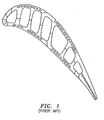
- the turbine engine component 10 such as a turbine blade, has an airfoil portion 12, a platform 14, and a root portion 16.
- the airfoil portion 12 has a tip 18.
- a cooling microcircuit 20 is imbedded within the airfoil portion 12.
- the imbedded cooling microcircuit 20 receives a coolant flow stream from an inlet 24 formed within the root portion 16.
- the inlet 24 is preferably positioned adjacent a leading edge of the root portion 16.
- the inlet 24 may communicate with any suitable source of cooling fluid such as engine bleed air.
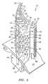
- the coolant flow stream is allowed to flow radially upward (in a direction away from the platform 14) through a first leg 26 of the cooling microcircuit 20 so as to take advantage of the natural pumping force.
- the cooling microcircuit 20 may have a serpentine configuration.
- the tip cooling circuit 30 comprises a plurality of spaced apart flow passages 70.
- Each flow passage 70 has an inlet which may communicate with and receive coolant from the first leg 26 as well as from a U-shaped flow turn portion 34 connecting the legs 26 and 28.
- each of the legs 26 and 28 has a plurality of cooling devices 80.
- the cooling devices 80 may have any desired shape. While it is preferred that the cooling devices be diamond shaped, they may also be cylindrical or cubed shaped. If a diamond shaped cooling device is used, it is preferred that the tip 86 of the diamond shape be aligned with the direction of the cooling fluid flowing through the respective one of the legs 24 and 26. The angle between the surfaces forming the tip 86 is important and should preferably be in the range of from 30 to 60 degrees.
- each cooling device 80 could have a cube shape.
- one of the sides of the cube should be oriented substantially normal to the direction of flow of the cooling fluid in the leg in which the cooling device 80 is located.
- a plurality of cooling devices 80 may be positioned within each of the legs 24 and 26.
- the cooling devices 80 in each leg are arranged in a staggered configuration.
- the cooling microcircuit 20 may be provided with a third leg 36 in which the coolant flows radially upward.
- the tip circuit 32 also may comprise a plurality of spaced apart flow passages 72.
- Each flow passage 72 may have an inlet which communicates with the third leg 36 of the cooling microcircuit 20 so as to receive coolant therefrom.
- Each cooling circuit passage 70 and 72 has a fluid outlet or exit 33 which allows cooling fluid to flow over a surface of the airfoil portion 12.
- the exits 33 are configured to allow the coolant to exit on the pressure side 35 of the airfoil portion 12.
- the tip cooling exits 33 from the circuits 30 and 32 may extend from a point near the leading edge 44 to a point near the trailing edge 50 of the airfoil portion 12.
- a root inlet refresher leg 38 may be fabricated within the root portion 16.
- the root inlet refresher leg 38 is in fluid communication with the third leg 36 and may be used to insure adequate cooling flow in the third leg 36.
- the root inlet refresher leg 38 may communicate with any suitable source (not shown) of cooling fluid such as engine bleed air.
- exit tabs 40 forming film slots 42 may be provided in the legs 26 and/or 28.
- the exit tabs 40 and film slots 42 allow coolant fluid to flow from the legs 26 and/or 28 onto a surface of the airfoil portion.
- the surface may be the pressure side surface 35 or the suction side surface 37. Fluid exiting the slots 42 helps form a cooling film over one or more of the exterior surfaces of the turbine engine component 10.
- Such film slots 42 may be useful in an open-cooling system.
- the leading edge 44 of the airfoil portion 12 may be provided with a plurality of fluid outlets or exits 46 which allow a film of coolant to flow over the leading edge portions of the pressure side 35 and the suction side 37 of the airfoil portion 12.
- the outlets or exits 46 may be supplied with coolant from a supply cavity 48.
- the supply cavity 48 may communicate directly with a source (not shown) of cooling fluid, such as engine bleed air, or alternatively, the supply cavity 48 may be in fluid communication with the first leg 26.
- the cooling microcircuit of the present invention may also be used in a closed loop system without film cooling for industrial gas turbine applications where the external thermal load is not as high as that for aircraft engine applications.
- the cooling microcircuit arrangement of the present invention may be formed using any suitable technique known in the art.
- one or more sheets formed from a refractory metal material may be configured in the shape of the cooling microcircuit arrangement 20 including the inlet 24 and the root inlet refresher leg 38, the legs 26, 28, and 36, the tip cooling microcircuits 30 and 32, the exits 33, the tabs 40, and the film slots 42.
- the refractory metal material sheets may be placed or positioned within a mold cavity.
- the turbine engine component 10 including the airfoil portion 12, the platform 14, and the root portion 16 may be cast from any suitable metal known in the art such as a nickel based superalloy, a titanium based superalloy, or an iron based superalloy.
- the refractory metal material sheets may be removed using any suitable means known in the art, leaving the cooling microcircuit arrangement 20 of the present invention.
Landscapes
- Engineering & Computer Science (AREA)
- Mechanical Engineering (AREA)
- General Engineering & Computer Science (AREA)
- Turbine Rotor Nozzle Sealing (AREA)
Applications Claiming Priority (1)
| Application Number | Priority Date | Filing Date | Title |
|---|---|---|---|
| US11/447,463 US20100247328A1 (en) | 2006-06-06 | 2006-06-06 | Microcircuit cooling for blades |
Publications (2)
| Publication Number | Publication Date |
|---|---|
| EP1865151A2 true EP1865151A2 (de) | 2007-12-12 |
| EP1865151A3 EP1865151A3 (de) | 2014-06-25 |
Family
ID=38521344
Family Applications (1)
| Application Number | Title | Priority Date | Filing Date |
|---|---|---|---|
| EP07252282.4A Withdrawn EP1865151A3 (de) | 2006-06-06 | 2007-06-06 | Kühlung mit Mikrokanälen für Turbinenschaufeln |
Country Status (3)
| Country | Link |
|---|---|
| US (1) | US20100247328A1 (de) |
| EP (1) | EP1865151A3 (de) |
| JP (1) | JP2007327494A (de) |
Cited By (3)
| Publication number | Priority date | Publication date | Assignee | Title |
|---|---|---|---|---|
| EP2223753A1 (de) * | 2009-02-17 | 2010-09-01 | United Technologies Corporation | Verfahren und feuerfester Metallkern zur Erzeugung von Mikroschaltungen mit unterschiedlicher Dicke für Turbinenmotorkomponente |
| CN102373962A (zh) * | 2010-08-09 | 2012-03-14 | 通用电气公司 | 叶片组件冷却装置和用于形成叶片组件的方法 |
| EP3670841A1 (de) * | 2018-11-09 | 2020-06-24 | United Technologies Corporation | Schaufel mit hybrider haut-kern-passagennachversorgung |
Families Citing this family (11)
| Publication number | Priority date | Publication date | Assignee | Title |
|---|---|---|---|---|
| US9995148B2 (en) | 2012-10-04 | 2018-06-12 | General Electric Company | Method and apparatus for cooling gas turbine and rotor blades |
| US9850762B2 (en) | 2013-03-13 | 2017-12-26 | General Electric Company | Dust mitigation for turbine blade tip turns |
| CA2950011C (en) | 2014-05-29 | 2020-01-28 | General Electric Company | Fastback turbulator |
| US10364684B2 (en) | 2014-05-29 | 2019-07-30 | General Electric Company | Fastback vorticor pin |
| WO2016025054A2 (en) | 2014-05-29 | 2016-02-18 | General Electric Company | Engine components with cooling features |
| US9957816B2 (en) | 2014-05-29 | 2018-05-01 | General Electric Company | Angled impingement insert |
| US10422235B2 (en) | 2014-05-29 | 2019-09-24 | General Electric Company | Angled impingement inserts with cooling features |
| US10233775B2 (en) | 2014-10-31 | 2019-03-19 | General Electric Company | Engine component for a gas turbine engine |
| US10280785B2 (en) | 2014-10-31 | 2019-05-07 | General Electric Company | Shroud assembly for a turbine engine |
| US10808571B2 (en) * | 2017-06-22 | 2020-10-20 | Raytheon Technologies Corporation | Gaspath component including minicore plenums |
| US11333023B2 (en) | 2018-11-09 | 2022-05-17 | Raytheon Technologies Corporation | Article having cooling passage network with inter-row sub-passages |
Family Cites Families (10)
| Publication number | Priority date | Publication date | Assignee | Title |
|---|---|---|---|---|
| US4407632A (en) * | 1981-06-26 | 1983-10-04 | United Technologies Corporation | Airfoil pedestaled trailing edge region cooling configuration |
| US4587700A (en) * | 1984-06-08 | 1986-05-13 | The Garrett Corporation | Method for manufacturing a dual alloy cooled turbine wheel |
| JP3377563B2 (ja) * | 1993-09-08 | 2003-02-17 | 三菱重工業株式会社 | ガスタービンの空気冷却動翼 |
| US6932571B2 (en) * | 2003-02-05 | 2005-08-23 | United Technologies Corporation | Microcircuit cooling for a turbine blade tip |
| US6832889B1 (en) * | 2003-07-09 | 2004-12-21 | General Electric Company | Integrated bridge turbine blade |
| US6981840B2 (en) * | 2003-10-24 | 2006-01-03 | General Electric Company | Converging pin cooled airfoil |
| US7207775B2 (en) * | 2004-06-03 | 2007-04-24 | General Electric Company | Turbine bucket with optimized cooling circuit |
| US7478994B2 (en) * | 2004-11-23 | 2009-01-20 | United Technologies Corporation | Airfoil with supplemental cooling channel adjacent leading edge |
| US7438527B2 (en) * | 2005-04-22 | 2008-10-21 | United Technologies Corporation | Airfoil trailing edge cooling |
| US7293961B2 (en) * | 2005-12-05 | 2007-11-13 | General Electric Company | Zigzag cooled turbine airfoil |
-
2006
- 2006-06-06 US US11/447,463 patent/US20100247328A1/en not_active Abandoned
-
2007
- 2007-06-06 JP JP2007149913A patent/JP2007327494A/ja active Pending
- 2007-06-06 EP EP07252282.4A patent/EP1865151A3/de not_active Withdrawn
Cited By (6)
| Publication number | Priority date | Publication date | Assignee | Title |
|---|---|---|---|---|
| EP2223753A1 (de) * | 2009-02-17 | 2010-09-01 | United Technologies Corporation | Verfahren und feuerfester Metallkern zur Erzeugung von Mikroschaltungen mit unterschiedlicher Dicke für Turbinenmotorkomponente |
| US8347947B2 (en) | 2009-02-17 | 2013-01-08 | United Technologies Corporation | Process and refractory metal core for creating varying thickness microcircuits for turbine engine components |
| US9038700B2 (en) | 2009-02-17 | 2015-05-26 | United Technologies Corporation | Process and refractory metal core for creating varying thickness microcircuits for turbine engine components |
| CN102373962A (zh) * | 2010-08-09 | 2012-03-14 | 通用电气公司 | 叶片组件冷却装置和用于形成叶片组件的方法 |
| EP3670841A1 (de) * | 2018-11-09 | 2020-06-24 | United Technologies Corporation | Schaufel mit hybrider haut-kern-passagennachversorgung |
| US11180998B2 (en) | 2018-11-09 | 2021-11-23 | Raytheon Technologies Corporation | Airfoil with skincore passage resupply |
Also Published As
| Publication number | Publication date |
|---|---|
| US20100247328A1 (en) | 2010-09-30 |
| EP1865151A3 (de) | 2014-06-25 |
| JP2007327494A (ja) | 2007-12-20 |
Similar Documents
| Publication | Publication Date | Title |
|---|---|---|
| EP1865151A2 (de) | Kühlung mit Mikrokanälen für Turbinenschaufeln | |
| US20070104576A1 (en) | Peripheral microcircuit serpentine cooling for turbine airfoils | |
| EP1878874B1 (de) | Integrierte Mikrokanäle für Schaufeln | |
| US8562295B1 (en) | Three piece bonded thin wall cooled blade | |
| US10400609B2 (en) | Airfoil cooling circuits | |
| EP1873354B1 (de) | Vorderkantenkühlung über Chevron-Streifen | |
| EP0852284B1 (de) | Wirbelelementkonstruktion für kühlkanäle einer Gasturbinenschaufel | |
| US8864469B1 (en) | Turbine rotor blade with super cooling | |
| US8608430B1 (en) | Turbine vane with near wall multiple impingement cooling | |
| EP1900904B1 (de) | Multiperipherisch Serpentinen-Mikroverläufe für Schaufel mit hohem Leistungsverhältnis | |
| EP1813776A2 (de) | Mikrokühlkanal für kleine Gasturbinenschaufel | |
| US8568097B1 (en) | Turbine blade with core print-out hole | |
| US8317474B1 (en) | Turbine blade with near wall cooling | |
| JP2007146835A (ja) | タービンエンジン構成要素およびタービンエンジン構成要素の作製方法 | |
| JP2008144760A (ja) | タービンエンジン構成要素およびそのエアフォイル部を形成する方法 | |
| JP2008032006A (ja) | 径方向に分割された蛇行微細回路 | |
| EP1790822B1 (de) | Kühlung mit Mikrokanälen für Turbinenschaufeln | |
| US9163518B2 (en) | Full coverage trailing edge microcircuit with alternating converging exits | |
| EP1882819B1 (de) | In Schaufelplattform, Schaufelspitze und Schaufelblatt integrierte Mikrokanäle für Turbinenschaufeln | |
| CA2513036C (en) | Airfoil cooling passage trailing edge flow restriction | |
| US8382431B1 (en) | Turbine rotor blade | |
| WO2016022140A1 (en) | Cooling passages for turbine engine components |
Legal Events
| Date | Code | Title | Description |
|---|---|---|---|
| PUAI | Public reference made under article 153(3) epc to a published international application that has entered the european phase |
Free format text: ORIGINAL CODE: 0009012 |
|
| AK | Designated contracting states |
Kind code of ref document: A2 Designated state(s): AT BE BG CH CY CZ DE DK EE ES FI FR GB GR HU IE IS IT LI LT LU LV MC MT NL PL PT RO SE SI SK TR |
|
| AX | Request for extension of the european patent |
Extension state: AL BA HR MK YU |
|
| PUAL | Search report despatched |
Free format text: ORIGINAL CODE: 0009013 |
|
| AK | Designated contracting states |
Kind code of ref document: A3 Designated state(s): AT BE BG CH CY CZ DE DK EE ES FI FR GB GR HU IE IS IT LI LT LU LV MC MT NL PL PT RO SE SI SK TR |
|
| AX | Request for extension of the european patent |
Extension state: AL BA HR MK RS |
|
| RIC1 | Information provided on ipc code assigned before grant |
Ipc: F01D 5/18 20060101AFI20140522BHEP |
|
| AKY | No designation fees paid | ||
| AXX | Extension fees paid |
Extension state: RS Extension state: MK Extension state: BA Extension state: HR Extension state: AL |
|
| REG | Reference to a national code |
Ref country code: DE Ref legal event code: R108 |
|
| REG | Reference to a national code |
Ref country code: DE Ref legal event code: R108 Effective date: 20150304 |
|
| STAA | Information on the status of an ep patent application or granted ep patent |
Free format text: STATUS: THE APPLICATION IS DEEMED TO BE WITHDRAWN |
|
| 18D | Application deemed to be withdrawn |
Effective date: 20150106 |