EP1865152A2 - Mikrokühlkanäle für Turbinenschaufeln - Google Patents
Mikrokühlkanäle für Turbinenschaufeln Download PDFInfo
- Publication number
- EP1865152A2 EP1865152A2 EP07252300A EP07252300A EP1865152A2 EP 1865152 A2 EP1865152 A2 EP 1865152A2 EP 07252300 A EP07252300 A EP 07252300A EP 07252300 A EP07252300 A EP 07252300A EP 1865152 A2 EP1865152 A2 EP 1865152A2
- Authority
- EP
- European Patent Office
- Prior art keywords
- microcircuit
- cooling
- pedestals
- pedestal
- portions
- Prior art date
- Legal status (The legal status is an assumption and is not a legal conclusion. Google has not performed a legal analysis and makes no representation as to the accuracy of the status listed.)
- Granted
Links
- 238000001816 cooling Methods 0.000 title claims abstract description 55
- 239000002826 coolant Substances 0.000 claims abstract description 18
- 239000012530 fluid Substances 0.000 claims abstract description 12
- NJPPVKZQTLUDBO-UHFFFAOYSA-N novaluron Chemical compound C1=C(Cl)C(OC(F)(F)C(OC(F)(F)F)F)=CC=C1NC(=O)NC(=O)C1=C(F)C=CC=C1F NJPPVKZQTLUDBO-UHFFFAOYSA-N 0.000 claims description 30
- 239000012809 cooling fluid Substances 0.000 claims description 14
- 239000007789 gas Substances 0.000 description 4
- 239000000463 material Substances 0.000 description 2
- 230000003247 decreasing effect Effects 0.000 description 1
- 230000004907 flux Effects 0.000 description 1
- 230000037406 food intake Effects 0.000 description 1
- 239000000203 mixture Substances 0.000 description 1
- 230000004048 modification Effects 0.000 description 1
- 238000012986 modification Methods 0.000 description 1
Images

Classifications
-
- F—MECHANICAL ENGINEERING; LIGHTING; HEATING; WEAPONS; BLASTING
- F01—MACHINES OR ENGINES IN GENERAL; ENGINE PLANTS IN GENERAL; STEAM ENGINES
- F01D—NON-POSITIVE DISPLACEMENT MACHINES OR ENGINES, e.g. STEAM TURBINES
- F01D5/00—Blades; Blade-carrying members; Heating, heat-insulating, cooling or antivibration means on the blades or the members
- F01D5/12—Blades
- F01D5/14—Form or construction
- F01D5/18—Hollow blades, i.e. blades with cooling or heating channels or cavities; Heating, heat-insulating or cooling means on blades
- F01D5/187—Convection cooling
-
- F—MECHANICAL ENGINEERING; LIGHTING; HEATING; WEAPONS; BLASTING
- F05—INDEXING SCHEMES RELATING TO ENGINES OR PUMPS IN VARIOUS SUBCLASSES OF CLASSES F01-F04
- F05D—INDEXING SCHEME FOR ASPECTS RELATING TO NON-POSITIVE-DISPLACEMENT MACHINES OR ENGINES, GAS-TURBINES OR JET-PROPULSION PLANTS
- F05D2260/00—Function
- F05D2260/20—Heat transfer, e.g. cooling
- F05D2260/221—Improvement of heat transfer
- F05D2260/2214—Improvement of heat transfer by increasing the heat transfer surface
Definitions
- the turbine airfoils are exposed to temperatures well above their material limits.
- Industry practice uses air from the compressor section of the engine to cool the airfoil material. This cooling air is fed through the root of the airfoil into a series of internal cavities or channels that flow radially from root to tip. The coolant is then injected into the hot mainstream flow through film-cooling holes.
- the secondary flows of a gas turbine blade are driven by the pressure difference between the flow source and the flow exit under high rotational forces.
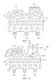
- the turbine blades rotate about an axis of rotation 11.
- a series of cooling microcircuits 10 are placed inside the walls 12 and 14 of the airfoil portion 16.
- Each of the cooling microcircuits 10 has a plurality of outlets or slots 15 for allowing a film of cooling fluid to flow over external surfaces of the airfoil portion 16.
- each cooling microcircuit 10 heats up, the coolant temperature increases, thus increasing the microcircuit convective efficiency.
- the other form of cooling which may be required for this type of turbine airfoil is film cooling as the cooling air discharges into the mainstream through a microcircuit slot 15.
- FIG. 2 illustrates a cooling microcircuit configuration 18 which may be incorporated into one or more of the walls 12 and 14, typically the pressure side wall 12.
- the configuration 18 has three inlets 20 for introducing a cooling fluid into the microcircuit, a microcircuit pedestal bank 21, and two slot exits 22.
- the shape of the pedestals 24 was conceived so that a minimum metering area may be provided for the coolant flow before it enters each of the slots 22. Initially, the symmetry of each of the last pedestals 24 seems to indicate uniform flow and flow re-distribution to fill the slot exit 22.
- one of the cooling fluid jets 23, as shown in FIG. 3 tends to overpower one 25 of the other exit jets.
- the film exiting the cooling microcircuit slots 22 is uneven. The resulting film protection is decreased, substantially leading to entrapment of hot gases in the side of the lower momentum jet.
- a cooling microcircuit which produces substantially even jets of cooling fluid exiting the microcircuit slots.
- a cooling microcircuit for use in a turbine engine component, such as a turbine blade, having an airfoil portion.
- the microcircuit broadly comprises at least one inlet slot for introducing a flow of coolant into the cooling microcircuit, a plurality of fluid exit slots for distributing a film of the coolant over the airfoil portion, and means for substantially preventing one jet of the coolant exiting through one of the fluid exit slots from overpowering a second jet of the coolant exiting through the one fluid exit slot.
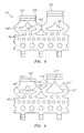
- FIGS. 4 - 6 there is shown a new cooling microcircuit arrangement 100 aimed at maintaining the flow more uniform, or substantially even, as it exits the microcircuit slots.
- the cooling microcircuits of the present invention may be incorporated into one or more of the pressure side and suction side walls of an airfoil portion of a turbine engine component such as a turbine blade.
- a cooling microcircuit 100 in accordance with the present invention has one or more cooling fluid inlet slots 102. After the cooling fluid enters the microcircuit 100, it passes through a plurality of rows of pedestals 104.
- the pedestals 104 may have any suitable shape known in the art. In a preferred embodiment of the present invention, the rows 94, 96, and 98 of pedestals 104 are staggered or offset with respect to each other.
- the pedestals 104 in one or more of the rows 94, 96, and 98 may be larger than the pedestals 104 in another one of the rows 94, 96, and 98.
- the cooling microcircuit 100 also has one or more fluid exit slots 106.
- each pedestal 108 has an arcuately shaped leading edge portion 110, arcuately shaped side portions 112 and 114, and a trailing edge portion 116 formed from two side portions 118 and 120, preferably arcuately shaped, joined by a tip portion 122.
- each of the pedestals 108 has an axis of symmetry 121 which aligns with a central axis 123 of the slot 106.
- the fluid exit slots 106 are formed with first sidewall portions 124 and second sidewall portions 126.
- the first sidewall portions 124 are at an angle with respect to the second sidewall portions 126.
- Each sidewall portion 124 begins at a point 128 which is substantially aligned with the leading edge portion 110 of each pedestal 108.
- Each sidewall portion 124 then extends to a point 129 substantially aligned with the tip portion 122.
- the sidewall portions 124 blend into the linear sidewall portions 126 and have an overall length greater than that in previous microcircuit configurations.
- the configuration of the last pedestal 108 is used in conjunction with the sidewall portions 124 and 126 leading to the exit slots 106 to form flow channels 125 for controlling the flow of the coolant exiting through the slots 106.
- the combination ot the sidewall portions 124 and 126 and the pedestals 108 allow for a more controlled flow of the cooling film in the flow channels 125.
- the jet of cooling fluid on one side of the pedestal 108 is not overpowered by the jet of cooling fluid on the other side of the pedestal 108.
- FIG. 5 there is shown a second embodiment of a cooling microcircuit 100'.
- the microcircuit 100' is provided with the two pedestals 108' and a third pedestal 109' which is positioned intermediate the two other pedestals 108'.
- the pedestals 108' have the same configuration and location as the pedestals 108 in the embodiment of FIG. 4.
- the third pedestal 109' is smaller in area and arranged in an offset manner with respect to the pedestals 108'.
- several round pedestals were removed from the row 96' closest to the exit slots 106'.
- the increased size of pedestal 109', relative to pedestal 96', in this configuration makes the cooling microcircuit more robust in creep resistance.
- the minimum metering area is also changed from its location in the prior art embodiments.
- the location of the minimum metering area is now between adjacent pedestals 108' and 109'.
- This flexibility allows for a modification of the sidewall portions 124' and 126' so as to be close to the microcircuit exit slots 106'.
- This new arrangement of pedestals substantially prevents one jet of exiting cooling fluid flow to overpower another jet of exiting cooling fluid flow if the momentum flux between the two jets is not balanced.
- the cooling microcircuit 100" has a pair of pedestals 108" and a third pedestal 109" positioned intermediate the two pedestals 108".
- the left hand pedestal 108" and pedestal 109" each have a configuration similar to the pedestals 108 in FIG. 4.
- the pedestal 109" occupies a portion of the last row of pedestals 96" and is smaller in area than either of the pedestals 108".
- the right hand pedestal 108" is larger in area as compared to the area of the left hand pedestal 108". This is due to the fact that the trailing edge 116" is longer due to the longer and more linear side portions 118" and 120" which are connected by the tip portion 122".
- the sidewall portions 124" and 126" may be extended so as to allow for the flow of cooling fluid to be straightened out even further before exiting at the microcircuit exit slots 106".
- the robust design of the embodiment of FIG. 6 helps resist creep deformation (strain) of the microcircuit external wall close to the microcircuit exit slots 106"; helps prevent the ingestion of hot gases into the microcircuit exit slots 106" by having a more uniform flow at the exit slots 106"; and helps attain high film coverage for film cooling the airfoil portion 16 of a turbine engine component.
- FIGS. 4 and 6 are advantageous because they have flow channels, formed by the sidewall portions and the last pair of pedestals, in the neck region leading to the exits slots which are longer by about 25 to 75% as compared to the channel length in the prior art embodiment shown in FIG. 3. As a result, there is more time for the cooling fluid flow in the neck region to coalesce and be more in balance.
Landscapes
- Engineering & Computer Science (AREA)
- Mechanical Engineering (AREA)
- General Engineering & Computer Science (AREA)
- Turbine Rotor Nozzle Sealing (AREA)
Applications Claiming Priority (1)
| Application Number | Priority Date | Filing Date | Title |
|---|---|---|---|
| US11/449,521 US7607890B2 (en) | 2006-06-07 | 2006-06-07 | Robust microcircuits for turbine airfoils |
Publications (3)
| Publication Number | Publication Date |
|---|---|
| EP1865152A2 true EP1865152A2 (de) | 2007-12-12 |
| EP1865152A3 EP1865152A3 (de) | 2011-02-16 |
| EP1865152B1 EP1865152B1 (de) | 2012-05-16 |
Family
ID=38328598
Family Applications (1)
| Application Number | Title | Priority Date | Filing Date |
|---|---|---|---|
| EP07252300A Ceased EP1865152B1 (de) | 2006-06-07 | 2007-06-07 | Mikrokühlkanäle für Turbinenschaufeln |
Country Status (3)
| Country | Link |
|---|---|
| US (1) | US7607890B2 (de) |
| EP (1) | EP1865152B1 (de) |
| JP (1) | JP2007327491A (de) |
Cited By (2)
| Publication number | Priority date | Publication date | Assignee | Title |
|---|---|---|---|---|
| EP2131011A3 (de) * | 2008-06-05 | 2012-08-29 | United Technologies Corporation | Teilchenbeständige-Kühllufteinströmung für Gasturbinenschaufel mit gekühlter Wand |
| EP2468433A3 (de) * | 2010-12-22 | 2017-05-17 | United Technologies Corporation | Minikern zum Bohren für Durchfluss |
Families Citing this family (10)
| Publication number | Priority date | Publication date | Assignee | Title |
|---|---|---|---|---|
| US8157527B2 (en) | 2008-07-03 | 2012-04-17 | United Technologies Corporation | Airfoil with tapered radial cooling passage |
| US8572844B2 (en) | 2008-08-29 | 2013-11-05 | United Technologies Corporation | Airfoil with leading edge cooling passage |
| US8303252B2 (en) | 2008-10-16 | 2012-11-06 | United Technologies Corporation | Airfoil with cooling passage providing variable heat transfer rate |
| US8109725B2 (en) | 2008-12-15 | 2012-02-07 | United Technologies Corporation | Airfoil with wrapped leading edge cooling passage |
| US8753083B2 (en) * | 2011-01-14 | 2014-06-17 | General Electric Company | Curved cooling passages for a turbine component |
| US10247099B2 (en) | 2013-10-29 | 2019-04-02 | United Technologies Corporation | Pedestals with heat transfer augmenter |
| US10174620B2 (en) | 2015-10-15 | 2019-01-08 | General Electric Company | Turbine blade |
| US10830072B2 (en) * | 2017-07-24 | 2020-11-10 | General Electric Company | Turbomachine airfoil |
| US10753210B2 (en) * | 2018-05-02 | 2020-08-25 | Raytheon Technologies Corporation | Airfoil having improved cooling scheme |
| US10975710B2 (en) | 2018-12-05 | 2021-04-13 | Raytheon Technologies Corporation | Cooling circuit for gas turbine engine component |
Citations (3)
| Publication number | Priority date | Publication date | Assignee | Title |
|---|---|---|---|---|
| EP1091092A2 (de) | 1999-10-05 | 2001-04-11 | United Technologies Corporation | Methode und Einrichtung zur Kühlung einer Wand in einer Gasturbine |
| EP1091091A2 (de) | 1999-10-05 | 2001-04-11 | United Technologies Corporation | Methode und Einrichtung zur Kühlung einer Wand in einer Gasturbine |
| US20050031450A1 (en) | 2003-08-08 | 2005-02-10 | Cunha Frank J. | Microcircuit airfoil mainbody |
Family Cites Families (1)
| Publication number | Priority date | Publication date | Assignee | Title |
|---|---|---|---|---|
| US6213714B1 (en) * | 1999-06-29 | 2001-04-10 | Allison Advanced Development Company | Cooled airfoil |
-
2006
- 2006-06-07 US US11/449,521 patent/US7607890B2/en active Active
-
2007
- 2007-06-04 JP JP2007147580A patent/JP2007327491A/ja active Pending
- 2007-06-07 EP EP07252300A patent/EP1865152B1/de not_active Ceased
Patent Citations (3)
| Publication number | Priority date | Publication date | Assignee | Title |
|---|---|---|---|---|
| EP1091092A2 (de) | 1999-10-05 | 2001-04-11 | United Technologies Corporation | Methode und Einrichtung zur Kühlung einer Wand in einer Gasturbine |
| EP1091091A2 (de) | 1999-10-05 | 2001-04-11 | United Technologies Corporation | Methode und Einrichtung zur Kühlung einer Wand in einer Gasturbine |
| US20050031450A1 (en) | 2003-08-08 | 2005-02-10 | Cunha Frank J. | Microcircuit airfoil mainbody |
Cited By (3)
| Publication number | Priority date | Publication date | Assignee | Title |
|---|---|---|---|---|
| EP2131011A3 (de) * | 2008-06-05 | 2012-08-29 | United Technologies Corporation | Teilchenbeständige-Kühllufteinströmung für Gasturbinenschaufel mit gekühlter Wand |
| EP2468433A3 (de) * | 2010-12-22 | 2017-05-17 | United Technologies Corporation | Minikern zum Bohren für Durchfluss |
| US9995145B2 (en) | 2010-12-22 | 2018-06-12 | United Technologies Corporation | Drill to flow mini core |
Also Published As
| Publication number | Publication date |
|---|---|
| EP1865152A3 (de) | 2011-02-16 |
| US7607890B2 (en) | 2009-10-27 |
| JP2007327491A (ja) | 2007-12-20 |
| EP1865152B1 (de) | 2012-05-16 |
| US20070286735A1 (en) | 2007-12-13 |
Similar Documents
| Publication | Publication Date | Title |
|---|---|---|
| EP1865152B1 (de) | Mikrokühlkanäle für Turbinenschaufeln | |
| US8066484B1 (en) | Film cooling hole for a turbine airfoil | |
| US7722327B1 (en) | Multiple vortex cooling circuit for a thin airfoil | |
| EP2823151B1 (de) | Schaufel mit verbesserten internen kühlkanalsockeln | |
| EP3652418B1 (de) | Wand eines bauteils für heissgas und zugehöriges bauteil | |
| US8449254B2 (en) | Branched airfoil core cooling arrangement | |
| US7753650B1 (en) | Thin turbine rotor blade with sinusoidal flow cooling channels | |
| EP3354846B1 (de) | Hinterflussserpentinenhohlräume und -kerne für schaufeln von gasturbinenmotoren | |
| US7967563B1 (en) | Turbine blade with tip section cooling channel | |
| US7563072B1 (en) | Turbine airfoil with near-wall spiral flow cooling circuit | |
| EP3330487B1 (de) | Vorderkantenhybridhohlräume und kerne für schaufeln eines gasturbinenmotors | |
| EP2235328B1 (de) | Schaufelkühlung | |
| US8052390B1 (en) | Turbine airfoil with showerhead cooling | |
| EP2899370B1 (de) | Turbinenschaufel mit Wirbelkühlkanal und Kühlverfahren dafür | |
| EP3342978B1 (de) | Integrierte squealer-taschenspitze und -spitzenregal mit hybrider und spitzenflaggenkern | |
| EP2615245B1 (de) | Filmgekühlte Turbinenschaufel mit Furchensegmenten auf der Aussenfläche | |
| JP2001214707A (ja) | 勾配付きフイルム冷却を備えるタービンノズル | |
| WO2013138009A1 (en) | Improved cooling pedestal array | |
| US20180328190A1 (en) | Gas turbine engine with film holes | |
| US10605170B2 (en) | Engine component with film cooling | |
| CN110043325B (zh) | 带有成组冷却孔的发动机构件 | |
| EP2634370B1 (de) | Turbinenschaufel mit einem Kernhohlraum mit einer konturierten Drehung | |
| EP2721259B1 (de) | Rotorschaufelwurzelabschnitt mit kühldurchlass und verfahren zur zufuhr von kühlmittel an eine rotorschaufel | |
| CN106468180A (zh) | 用于燃气涡轮发动机的发动机构件 | |
| CN108506048A (zh) | 用于涡轮发动机的膜孔布置 |
Legal Events
| Date | Code | Title | Description |
|---|---|---|---|
| PUAI | Public reference made under article 153(3) epc to a published international application that has entered the european phase |
Free format text: ORIGINAL CODE: 0009012 |
|
| AK | Designated contracting states |
Kind code of ref document: A2 Designated state(s): AT BE BG CH CY CZ DE DK EE ES FI FR GB GR HU IE IS IT LI LT LU LV MC MT NL PL PT RO SE SI SK TR |
|
| AX | Request for extension of the european patent |
Extension state: AL BA HR MK YU |
|
| PUAL | Search report despatched |
Free format text: ORIGINAL CODE: 0009013 |
|
| AK | Designated contracting states |
Kind code of ref document: A3 Designated state(s): AT BE BG CH CY CZ DE DK EE ES FI FR GB GR HU IE IS IT LI LT LU LV MC MT NL PL PT RO SE SI SK TR |
|
| AX | Request for extension of the european patent |
Extension state: AL BA HR MK RS |
|
| 17P | Request for examination filed |
Effective date: 20110811 |
|
| AKX | Designation fees paid |
Designated state(s): DE GB |
|
| GRAP | Despatch of communication of intention to grant a patent |
Free format text: ORIGINAL CODE: EPIDOSNIGR1 |
|
| GRAS | Grant fee paid |
Free format text: ORIGINAL CODE: EPIDOSNIGR3 |
|
| GRAA | (expected) grant |
Free format text: ORIGINAL CODE: 0009210 |
|
| AK | Designated contracting states |
Kind code of ref document: B1 Designated state(s): DE GB |
|
| REG | Reference to a national code |
Ref country code: GB Ref legal event code: FG4D |
|
| REG | Reference to a national code |
Ref country code: DE Ref legal event code: R081 Ref document number: 602007022627 Country of ref document: DE Owner name: UNITED TECHNOLOGIES CORP. (N.D.GES.D. STAATES , US Free format text: FORMER OWNER: UNITED TECHNOLOGIES CORP., HARTFORD, CONN., US |
|
| REG | Reference to a national code |
Ref country code: DE Ref legal event code: R096 Ref document number: 602007022627 Country of ref document: DE Effective date: 20120726 |
|
| PLBE | No opposition filed within time limit |
Free format text: ORIGINAL CODE: 0009261 |
|
| STAA | Information on the status of an ep patent application or granted ep patent |
Free format text: STATUS: NO OPPOSITION FILED WITHIN TIME LIMIT |
|
| 26N | No opposition filed |
Effective date: 20130219 |
|
| REG | Reference to a national code |
Ref country code: DE Ref legal event code: R097 Ref document number: 602007022627 Country of ref document: DE Effective date: 20130219 |
|
| REG | Reference to a national code |
Ref country code: DE Ref legal event code: R082 Ref document number: 602007022627 Country of ref document: DE Representative=s name: SCHMITT-NILSON SCHRAUD WAIBEL WOHLFROM PATENTA, DE |
|
| REG | Reference to a national code |
Ref country code: DE Ref legal event code: R082 Ref document number: 602007022627 Country of ref document: DE Representative=s name: SCHMITT-NILSON SCHRAUD WAIBEL WOHLFROM PATENTA, DE Ref country code: DE Ref legal event code: R081 Ref document number: 602007022627 Country of ref document: DE Owner name: UNITED TECHNOLOGIES CORP. (N.D.GES.D. STAATES , US Free format text: FORMER OWNER: UNITED TECHNOLOGIES CORPORATION, HARTFORD, CONN., US |
|
| PGFP | Annual fee paid to national office [announced via postgrant information from national office to epo] |
Ref country code: GB Payment date: 20170526 Year of fee payment: 11 Ref country code: DE Payment date: 20170522 Year of fee payment: 11 |
|
| REG | Reference to a national code |
Ref country code: DE Ref legal event code: R119 Ref document number: 602007022627 Country of ref document: DE |
|
| GBPC | Gb: european patent ceased through non-payment of renewal fee |
Effective date: 20180607 |
|
| PG25 | Lapsed in a contracting state [announced via postgrant information from national office to epo] |
Ref country code: DE Free format text: LAPSE BECAUSE OF NON-PAYMENT OF DUE FEES Effective date: 20190101 Ref country code: GB Free format text: LAPSE BECAUSE OF NON-PAYMENT OF DUE FEES Effective date: 20180607 |