EP1865172A2 - Dispositif et procédé de démarrage d'un moteur à turbine à gaz - Google Patents
Dispositif et procédé de démarrage d'un moteur à turbine à gaz Download PDFInfo
- Publication number
- EP1865172A2 EP1865172A2 EP07252221A EP07252221A EP1865172A2 EP 1865172 A2 EP1865172 A2 EP 1865172A2 EP 07252221 A EP07252221 A EP 07252221A EP 07252221 A EP07252221 A EP 07252221A EP 1865172 A2 EP1865172 A2 EP 1865172A2
- Authority
- EP
- European Patent Office
- Prior art keywords
- rotor
- windings
- current
- stator
- starting
- Prior art date
- Legal status (The legal status is an assumption and is not a legal conclusion. Google has not performed a legal analysis and makes no representation as to the accuracy of the status listed.)
- Withdrawn
Links
- 238000000034 method Methods 0.000 title claims abstract description 27
- 238000004804 winding Methods 0.000 claims abstract description 75
- 238000012544 monitoring process Methods 0.000 claims 2
- 238000013459 approach Methods 0.000 description 5
- 230000005284 excitation Effects 0.000 description 3
- 230000009977 dual effect Effects 0.000 description 2
- 230000004044 response Effects 0.000 description 2
- 239000007858 starting material Substances 0.000 description 2
- 238000004891 communication Methods 0.000 description 1
- 230000001419 dependent effect Effects 0.000 description 1
- 238000013461 design Methods 0.000 description 1
- 230000005288 electromagnetic effect Effects 0.000 description 1
- 230000006872 improvement Effects 0.000 description 1
- 238000012986 modification Methods 0.000 description 1
- 230000004048 modification Effects 0.000 description 1
- 230000008569 process Effects 0.000 description 1
- 238000012552 review Methods 0.000 description 1
Images


Classifications
-
- F—MECHANICAL ENGINEERING; LIGHTING; HEATING; WEAPONS; BLASTING
- F02—COMBUSTION ENGINES; HOT-GAS OR COMBUSTION-PRODUCT ENGINE PLANTS
- F02C—GAS-TURBINE PLANTS; AIR INTAKES FOR JET-PROPULSION PLANTS; CONTROLLING FUEL SUPPLY IN AIR-BREATHING JET-PROPULSION PLANTS
- F02C7/00—Features, components parts, details or accessories, not provided for in, or of interest apart form groups F02C1/00 - F02C6/00; Air intakes for jet-propulsion plants
- F02C7/26—Starting; Ignition
- F02C7/268—Starting drives for the rotor, acting directly on the rotor of the gas turbine to be started
- F02C7/275—Mechanical drives
Definitions
- This invention relates to the field of gas turbine engines. More precisely, the invention pertains to a method and apparatus for starting such machines.
- Starting a gas turbine aircraft engine on the ground with a sensorless brushless starter-generator typically involves sending a predetermined sequence of current signals to the windings of the stator to cause the rotor magnets to begin to rotate in accordance with the predetermined sequence of current signals provided to the corresponding windings of the stator. Since the rotor position is not known, a trial and error approach is typically used, wherein a rotor position is assumed and current provided to the stator based on the assumed position and, if starting is not successful, a different rotor position is assumed, and the process is repeated, until starting occurs.
- a method for starting a gas turbine engine drivingly coupled to a brushless machine comprising a rotor and a stator having windings, the method comprising the steps of: providing DC current to at least one of the windings to' position the rotor at a desired position with respect to the stator; and then energizing the windings of the stator to start the gas turbine engine.
- a method for starting a turbofan engine drivingly coupled to a starter-generator comprising a rotor and a corresponding stator comprising windings comprising providing DC current to at least one of the windings for a sufficient time to stop residual rotation of the rotor; providing DC current to at least one the windings to position the rotor at a desired position with respect to the stator; and then energizing the windings of the stator to start the turbofan engine.
- a turbofan engine comprising a shaft drivingly connected to an electric motor, the motor having a permanent magnetic rotor and a stator comprising a winding, the motor further having a rotor stopping apparatus adapted to stop residual rotor rotation, a rotor repositioning apparatus adapted to position the rotor in a desired position prior to motor starting, a motor starting apparatus for starting the turbofan engine.
- FIG. 1 there is shown an embodiment of a system for using a brushless sensorless machine as a starter for rotating equipment, which in this embodiment is a gas turbine aircraft engine such as a turbofan or a turboprop.
- a set of rotating blades 4 is mounted to a shaft 5, which is coupled to the permanent magnet rotors 6a, 6b (which are also referred to, for simplicity, as rotors 6) of sensorless brushless machines 7a, 7b (which are also referred to, for simplicity, as machines 7), each of which includes a stator 9a, 9b (which are also referred to, for simplicity, as stators 9).
- the rotors 6 rotate relative to stators 9.
- One stator 9a includes first group of windings 8 and the other stator 9b includes a second group of windings 10.
- the magnets of rotors 6 are preferably aligned relative to one another.
- the windings 8, 10 of machines 7 are electrically connected to respective power control units (PCU) 24a and 24b.
- the first group of windings 8 of machine 7a comprises 3-phase windings 12, 14 and 16, all of which are electrically connected to the power control unit 24a.
- the second group of windings 10 of machine 7b also comprises 3-phase windings 18, 20 and 22 electrically connected to power control unit 24b.
- the power control unit 24a In a starting or motoring mode, the power control unit 24a, inter alia, provides current to at least one winding of the first group of windings 8, as will be described further below.
- the current in windings 8 is adapted to cause rotation of rotor 6 relative to stator 9.
- the power control unit 24b receives a feedback signal provided by at least one winding of the second group of windings 10, which feedback signal may be used to determine the position of the moving rotor 6 with respect of the stator 9.
- machine 7b is used, in the above embodiment, as a rotor position detector, and that other rotor position detectors may be substituted therefor.
- sensorless in the present application is intended to mean that no specific or dedicated rotor position detector is required.
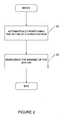
- a brushless sensorless machine start strategy is generally depicted.
- step 30 the rotor is automatically positioned at a desired position by appropriately energizing certain windings, as will be described further below.
- step 32 the windings of the stator are then sequentially energized, according to a given sequence, to force rotation of the rotor.
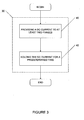
- FIG. 3 there is shown a general technique for automatically positioning the rotor at a desired position (step 30 of Figure 2).
- a DC current is provided (in response to a start command or signal, such as from a pilot) to at least one, and preferably at least two phases selected from of the two sets of windings 8, 10.
- the two phases are selected from the same set of windings (i.e. as between sets 8 and 10), and preferably the DC current signal is provided to at least two phases of the first group of windings (e.g. 8) by its power control unit (e.g. 24a).
- the DC current is provided to the windings for a predetermined amount of time, preferably sufficiently long to enable the rotor 6 to stop windmilling rotation (if any) and is positioned with respect to the stator, in response to the electromagnetic effect the DC current energized windings has on the rotor 6, so that the magnets of rotor 6 align with, and then stop, appropriately relative to the stationary magnetic poles temporarily created by the DC energization of the windings.
- the amount of time the DC current needs be applied, to ensure desired stopping and positioning of the rotor will vary depending on the torque and polar moment of inertia of the rotor system and the speed of rotation before the current is applied.
- the nature and strength of DC current applied will be dependent on the rotor and winding configuration, as well as the torque and polar moment of inertia of the rotor system and the speed of rotation before the current is applied.
- the two energized windings are spaced-apart from one another, circumferentially around the stator, such as would be the case for adjacent phases in a 3-phase machine. According to the described technique, the position of the rotor thus becomes known, since it has stopped and been positioned in a desired position.
- An apparatus implementing step 42 would be an example of a rotor stopping apparatus.
- un-energized windings of machine 7b are monitored to confirm when rotation is stopped (i.e. no generated voltages in the windings, meaning the rotor is stationary).
- the selected windings are then energized as described above to position the rotor in the desired position.
- An apparatus implementing the positioning of the rotor in such a way would be an example of a rotor repositioning apparatus.
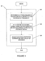
- step 32 there is shown one example of how the windings of the stator are energized (step 32) to start the gas turbine engine.
- An apparatus implementing step 32 at least in part would be an example of a motor starting apparatus.
- Machine 7 would also be an example of a motor starting apparatus.
- a phase excitation sequence of the first winding set 8 is performed, first at a low rate, and then at an ever-increasing frequency to accelerate machine, and thus the engine.
- Parameters related to this aspect of the present technique are known in the art, and include, for example, the polar moment of inertia of the engine, the applied torque, design characteristics of the starter motor (machine 7), and so on. The specifics of starting are not intended to form part of this invention.
- step 46 once a certain minimum rotational speed of the rotor is achieved, the voltage induced in the second winding set 10 by the passing rotor may be used as a feedback signal.
- the feedback signal is provided to the power control unit 24b and processed to provide a position of the rotor with respect to the stator. This information can be then used to appropriately control the excitation current provided to the first group of windings 8, to ensure the system is accelerated at the optimum rate (step 48).
- the two windings sets 8, 10 are provided spaced about one stator 9 - that is, in a "dual channel" machine of the type depicted in Figure 5 and described in more detail in applicant's copending US patent application serial no. 10/724,148, published June 2, 2005 as US2005/0116675 .
- a single stator is divided into two sectors, and the windings 8, 10 confined to respective sectors of the stator.
- Three-phase winding set 8 is electrically connected to power source P via a commutation circuit within PCU 24a and three-phase winding set 10 is preferably also selectively connected to power source P via commutation circuit within PCU 24b.
- Winding set 10 is also electrically connected to rotor position recognition circuit 26b within PCU 24b which is, in turn, connected for feedback communication with the commutation circuit of PCU 24a (as indicated by the stippled line).
- windings 8 are energized to cause rotor rotation, while the EMF induced in winding set 10 is fed back and processed for rotor position information, which is then provided to PCU 24a for control purposes, as described.
- the step of stopping/positioning the rotor 6 is achieved by sending a DC (i.e. non-alternating or unidirectional) current to at least two windings of the winding sets 8, 10, and preferably two windings of the same winding set (e.g. two phases of winding set 8).
- sensorless motor systems are known, and are suitable for use with the present technique. Any suitable sensorless machine system may be used.
- the above method thus stops, if necessary, the rotor if it was previously rotating (due to air flow through the engine, for instance). Furthermore, the positioning of the rotor with respect to the energized stator windings enables the positioning of the rotor magnets at a known (desired) position, such that the phase excitation sequence to be applied will always be from a correct point to cause the rotor rotation in the proper direction. The trial-and-error approach of the prior art is thus unnecessary.
- any number windings may be provided with DC current to fix rotor position.
- any suitable number of winding sets may be used.
- more than two such channels may be provided.
- Any suitable number of phases i.e. not only 3-phase
Landscapes
- Engineering & Computer Science (AREA)
- Chemical & Material Sciences (AREA)
- Combustion & Propulsion (AREA)
- Mechanical Engineering (AREA)
- General Engineering & Computer Science (AREA)
- Control Of Motors That Do Not Use Commutators (AREA)
- Motor And Converter Starters (AREA)
Applications Claiming Priority (1)
| Application Number | Priority Date | Filing Date | Title |
|---|---|---|---|
| US11/421,089 US7723931B2 (en) | 2006-05-31 | 2006-05-31 | Starting a gas turbine engine using a sensorless, brushless motor |
Publications (2)
| Publication Number | Publication Date |
|---|---|
| EP1865172A2 true EP1865172A2 (de) | 2007-12-12 |
| EP1865172A3 EP1865172A3 (de) | 2010-12-01 |
Family
ID=38198293
Family Applications (1)
| Application Number | Title | Priority Date | Filing Date |
|---|---|---|---|
| EP07252221A Withdrawn EP1865172A3 (de) | 2006-05-31 | 2007-05-31 | Dispositif et procédé de démarrage d'un moteur à turbine à gaz |
Country Status (4)
| Country | Link |
|---|---|
| US (1) | US7723931B2 (de) |
| EP (1) | EP1865172A3 (de) |
| CA (1) | CA2643764C (de) |
| WO (1) | WO2007137398A1 (de) |
Cited By (4)
| Publication number | Priority date | Publication date | Assignee | Title |
|---|---|---|---|---|
| EP2148422A1 (de) | 2008-07-22 | 2010-01-27 | Pratt & Whitney Canada Corp. | Motorantriebssystem und Verfahren zum Anfahren eines Motors |
| FR2966301A1 (fr) * | 2010-10-13 | 2012-04-20 | Messier Bugatti | Procede de gestion d'actionneurs electromecaniques a double bobinage. |
| EP3125423A4 (de) * | 2014-03-28 | 2017-11-29 | Kabushiki Kaisha Toyota Jidoshokki | Elektromotorsteuerungsvorrichtung |
| FR3156170A1 (fr) | 2023-12-05 | 2025-06-06 | Airbus Helicopters | Installation motrice munie d’un turbomoteur et d’un circuit de démarrage adaptatif et procédé de démarrage adaptatif d’un turbomoteur |
Families Citing this family (7)
| Publication number | Priority date | Publication date | Assignee | Title |
|---|---|---|---|---|
| US7508086B2 (en) * | 2006-03-24 | 2009-03-24 | General Electric Company | Aircraft engine starter/generator and controller |
| US8115434B2 (en) * | 2010-05-28 | 2012-02-14 | General Electric Company | High-speed self-cascaded electric machine |
| US9444376B2 (en) | 2013-02-22 | 2016-09-13 | Hamilton Sundstrand Corporation | Variable link sensorless brushless direct current motor controller for space and hardened applications |
| US9657645B2 (en) * | 2013-02-25 | 2017-05-23 | Pratt & Whitney Canada Corp. | Engine architecture using electric machine |
| US20150349685A1 (en) * | 2014-06-03 | 2015-12-03 | Nidec Motor Corporation | System and method for starting an electric motor |
| US10224848B2 (en) * | 2017-01-30 | 2019-03-05 | Pratt & Whitney Canada Corp. | Method and system for synchronizing generators |
| EP3583687A1 (de) * | 2017-02-16 | 2019-12-25 | Holcomb Scientific Research Limited | Mantelstrom-düsentriebwerk, angetrieben durch einen elektromotor mit leistung von einem hocheffizienten elektrischen generator |
Citations (1)
| Publication number | Priority date | Publication date | Assignee | Title |
|---|---|---|---|---|
| US20050237034A1 (en) | 2004-04-23 | 2005-10-27 | Patterson Stanley C | Fault tolerant architecture for permanent magnet starter generator subsystem |
Family Cites Families (12)
| Publication number | Priority date | Publication date | Assignee | Title |
|---|---|---|---|---|
| US5184456A (en) * | 1991-04-08 | 1993-02-09 | Avco Corporation | Gas turbine motor drive |
| US5495162A (en) * | 1993-05-12 | 1996-02-27 | Sundstrand Corporation | Position-and-velocity sensorless control for starter generator electrical system using generator back-EMF voltage |
| US5428275A (en) | 1993-05-12 | 1995-06-27 | Sundstrand Corporation | Controlled starting method for a gas turbine engine |
| US5461293A (en) * | 1993-05-12 | 1995-10-24 | Sundstrand Corporation | Rotor position detector |
| US5430362A (en) * | 1993-05-12 | 1995-07-04 | Sundstrand Corporation | Engine starting system utilizing multiple controlled acceleration rates |
| JP3385617B2 (ja) | 1995-01-27 | 2003-03-10 | 株式会社安川電機 | 回転位置検出器付き永久磁石形同期電動機の起動方法および電動機制御装置 |
| US5920162A (en) * | 1996-08-05 | 1999-07-06 | Sundstrand Corporation | Position control using variable exciter feed through |
| WO1998025014A2 (en) | 1996-12-03 | 1998-06-11 | Elliott Energy Systems, Inc. | Electrical system for turbine/alternator on common shaft |
| JP4249916B2 (ja) * | 2000-09-18 | 2009-04-08 | エドワーズ株式会社 | ブラシレスモータの制御回路、ブラシレスモータ装置、及び真空ポンプ装置 |
| US6836086B1 (en) * | 2002-03-08 | 2004-12-28 | Hamilton Sundstrand Corporation | Controlled starting system for a gas turbine engine |
| US6909263B2 (en) * | 2002-10-23 | 2005-06-21 | Honeywell International Inc. | Gas turbine engine starter-generator exciter starting system and method including a capacitance circuit element |
| US7242105B2 (en) | 2005-08-17 | 2007-07-10 | Hamilton Sundstrand Corporation | Electric engine start with two motors and single motor drive |
-
2006
- 2006-05-31 US US11/421,089 patent/US7723931B2/en active Active
-
2007
- 2007-05-10 WO PCT/CA2007/000836 patent/WO2007137398A1/en not_active Ceased
- 2007-05-10 CA CA2643764A patent/CA2643764C/en not_active Expired - Fee Related
- 2007-05-31 EP EP07252221A patent/EP1865172A3/de not_active Withdrawn
Patent Citations (1)
| Publication number | Priority date | Publication date | Assignee | Title |
|---|---|---|---|---|
| US20050237034A1 (en) | 2004-04-23 | 2005-10-27 | Patterson Stanley C | Fault tolerant architecture for permanent magnet starter generator subsystem |
Cited By (6)
| Publication number | Priority date | Publication date | Assignee | Title |
|---|---|---|---|---|
| EP2148422A1 (de) | 2008-07-22 | 2010-01-27 | Pratt & Whitney Canada Corp. | Motorantriebssystem und Verfahren zum Anfahren eines Motors |
| FR2966301A1 (fr) * | 2010-10-13 | 2012-04-20 | Messier Bugatti | Procede de gestion d'actionneurs electromecaniques a double bobinage. |
| EP3125423A4 (de) * | 2014-03-28 | 2017-11-29 | Kabushiki Kaisha Toyota Jidoshokki | Elektromotorsteuerungsvorrichtung |
| US9973122B2 (en) | 2014-03-28 | 2018-05-15 | Kabushiki Kaisha Toyota Jidoshokki | Electric motor control device |
| FR3156170A1 (fr) | 2023-12-05 | 2025-06-06 | Airbus Helicopters | Installation motrice munie d’un turbomoteur et d’un circuit de démarrage adaptatif et procédé de démarrage adaptatif d’un turbomoteur |
| EP4567266A1 (de) | 2023-12-05 | 2025-06-11 | Airbus Helicopters | Antriebsaggregat mit einem turbomotor und einem adaptiven startkreis und verfahren zum adaptiven starten eines turbomotors |
Also Published As
| Publication number | Publication date |
|---|---|
| CA2643764C (en) | 2014-12-23 |
| WO2007137398A1 (en) | 2007-12-06 |
| EP1865172A3 (de) | 2010-12-01 |
| CA2643764A1 (en) | 2007-12-06 |
| US7723931B2 (en) | 2010-05-25 |
| US20070296215A1 (en) | 2007-12-27 |
Similar Documents
| Publication | Publication Date | Title |
|---|---|---|
| EP1865172A2 (de) | Dispositif et procédé de démarrage d'un moteur à turbine à gaz | |
| US6528967B2 (en) | Permanent magnet brushless electric motor system and method of using same | |
| EP2432978B1 (de) | Starter/generator und steuerung für flugzeugmotoren | |
| EP2001121B1 (de) | Motorstartsystem mit Quadraturwechselstromerregung | |
| EP3004565B1 (de) | Strahltriebwerksanordnung und verfahren zur erzeugung von elektrizität | |
| EP3082250B1 (de) | Sensorlose steuerung einer synchronmaschine | |
| EP1906008A2 (de) | Für Startfunktion optimierter Motorstartergenerator | |
| EP2840702B1 (de) | Systeme für Synchronmotoren mit Feldwicklung mit Rotorpositionserfassung im Stillstand beim Start für Kraftfahrzeuge und verbessertes Einschwingverhalten zur Erzeugung | |
| US8593095B2 (en) | Wound field synchronous machine rotor tracking using a carrier injection sensorless signal and exciter current | |
| EP2045907B1 (de) | Verfahren zum Neustart einer dynamoelektrischen Maschine | |
| US20090256507A1 (en) | Method for operating sensorless and brushless motors | |
| US20040027077A1 (en) | Gas turbine engine starter generator with switchable exciter stator windings | |
| US9595900B2 (en) | Method and assembly for the turning gear operation of a turbo set | |
| US10476418B2 (en) | Synchronous electric power distribution startup system | |
| WO2006034344A1 (en) | Method and apparatus for controlling an engine start system | |
| JP2007512800A (ja) | 永久磁石機械におけるセンサレス制御のためのシステム | |
| EP3506490B1 (de) | Bürstenlose synchrone stromerzeugungsvorrichtung | |
| EP3023331A1 (de) | Luftfahrzeugantrieb und verfahren zur erzeugung elektrischer energie für ein luftfahrzeugversorgungssystem | |
| WO2021194482A1 (en) | Dual mode permanent magnet electric machine and turning gear system for aircraft gas turbine engines | |
| JP2001008490A (ja) | 永久磁石式同期電動機の制御装置、及び制御方法 | |
| JP3283377B2 (ja) | 直流電動機の同期起動装置 | |
| EP3021478B1 (de) | Zweistufige flussschaltmaschine für ein erzeugungssystem von elektrischem strom | |
| JP4291977B2 (ja) | ブラシレス・センサレスdcモータの駆動システム |
Legal Events
| Date | Code | Title | Description |
|---|---|---|---|
| PUAI | Public reference made under article 153(3) epc to a published international application that has entered the european phase |
Free format text: ORIGINAL CODE: 0009012 |
|
| AK | Designated contracting states |
Kind code of ref document: A2 Designated state(s): AT BE BG CH CY CZ DE DK EE ES FI FR GB GR HU IE IS IT LI LT LU LV MC MT NL PL PT RO SE SI SK TR |
|
| AX | Request for extension of the european patent |
Extension state: AL BA HR MK YU |
|
| PUAL | Search report despatched |
Free format text: ORIGINAL CODE: 0009013 |
|
| AK | Designated contracting states |
Kind code of ref document: A3 Designated state(s): AT BE BG CH CY CZ DE DK EE ES FI FR GB GR HU IE IS IT LI LT LU LV MC MT NL PL PT RO SE SI SK TR |
|
| AX | Request for extension of the european patent |
Extension state: AL BA HR MK RS |
|
| 17P | Request for examination filed |
Effective date: 20110531 |
|
| AKX | Designation fees paid |
Designated state(s): DE FR GB |
|
| 17Q | First examination report despatched |
Effective date: 20120423 |
|
| STAA | Information on the status of an ep patent application or granted ep patent |
Free format text: STATUS: THE APPLICATION IS DEEMED TO BE WITHDRAWN |
|
| 18D | Application deemed to be withdrawn |
Effective date: 20121106 |