EP1865202B1 - Pompe à eau pour étangs, aquariums, fontaines et analogues - Google Patents
Pompe à eau pour étangs, aquariums, fontaines et analogues Download PDFInfo
- Publication number
- EP1865202B1 EP1865202B1 EP07009460A EP07009460A EP1865202B1 EP 1865202 B1 EP1865202 B1 EP 1865202B1 EP 07009460 A EP07009460 A EP 07009460A EP 07009460 A EP07009460 A EP 07009460A EP 1865202 B1 EP1865202 B1 EP 1865202B1
- Authority
- EP
- European Patent Office
- Prior art keywords
- stator
- motor
- windings
- water pump
- poles
- Prior art date
- Legal status (The legal status is an assumption and is not a legal conclusion. Google has not performed a legal analysis and makes no representation as to the accuracy of the status listed.)
- Active
Links
Images


Classifications
-
- F—MECHANICAL ENGINEERING; LIGHTING; HEATING; WEAPONS; BLASTING
- F04—POSITIVE - DISPLACEMENT MACHINES FOR LIQUIDS; PUMPS FOR LIQUIDS OR ELASTIC FLUIDS
- F04D—NON-POSITIVE-DISPLACEMENT PUMPS
- F04D13/00—Pumping installations or systems
- F04D13/02—Units comprising pumps and their driving means
- F04D13/06—Units comprising pumps and their driving means the pump being electrically driven
- F04D13/0606—Canned motor pumps
- F04D13/064—Details of the magnetic circuit
-
- F—MECHANICAL ENGINEERING; LIGHTING; HEATING; WEAPONS; BLASTING
- F04—POSITIVE - DISPLACEMENT MACHINES FOR LIQUIDS; PUMPS FOR LIQUIDS OR ELASTIC FLUIDS
- F04D—NON-POSITIVE-DISPLACEMENT PUMPS
- F04D13/00—Pumping installations or systems
- F04D13/02—Units comprising pumps and their driving means
- F04D13/06—Units comprising pumps and their driving means the pump being electrically driven
- F04D13/0606—Canned motor pumps
- F04D13/0626—Details of the can
-
- H—ELECTRICITY
- H02—GENERATION; CONVERSION OR DISTRIBUTION OF ELECTRIC POWER
- H02K—DYNAMO-ELECTRIC MACHINES
- H02K3/00—Details of windings
- H02K3/04—Windings characterised by the conductor shape, form or construction, e.g. with bar conductors
- H02K3/18—Windings for salient poles
-
- H—ELECTRICITY
- H02—GENERATION; CONVERSION OR DISTRIBUTION OF ELECTRIC POWER
- H02K—DYNAMO-ELECTRIC MACHINES
- H02K5/00—Casings; Enclosures; Supports
- H02K5/04—Casings or enclosures characterised by the shape, form or construction thereof
- H02K5/12—Casings or enclosures characterised by the shape, form or construction thereof specially adapted for operating in liquid or gas
- H02K5/128—Casings or enclosures characterised by the shape, form or construction thereof specially adapted for operating in liquid or gas using air-gap sleeves or air-gap discs
-
- H—ELECTRICITY
- H02—GENERATION; CONVERSION OR DISTRIBUTION OF ELECTRIC POWER
- H02K—DYNAMO-ELECTRIC MACHINES
- H02K1/00—Details of the magnetic circuit
- H02K1/06—Details of the magnetic circuit characterised by the shape, form or construction
- H02K1/12—Stationary parts of the magnetic circuit
- H02K1/14—Stator cores with salient poles
- H02K1/146—Stator cores with salient poles consisting of a generally annular yoke with salient poles
-
- H—ELECTRICITY
- H02—GENERATION; CONVERSION OR DISTRIBUTION OF ELECTRIC POWER
- H02K—DYNAMO-ELECTRIC MACHINES
- H02K15/00—Processes or apparatus specially adapted for manufacturing, assembling, maintaining or repairing of dynamo-electric machines
- H02K15/06—Embedding prefabricated windings in the machines
- H02K15/062—Windings in slots; Salient pole windings
- H02K15/065—Windings consisting of complete sections, e.g. coils or waves
- H02K15/066—Windings consisting of complete sections, e.g. coils or waves inserted perpendicularly to the axis of the slots or inter-polar channels
Definitions
- the invention relates to a water pump for ponds, aquariums, fountains or the like according to the preamble of claim 1.
- the water pump should be designed for a power range between about 100 and 900 watts.
- Such, in the pond area already relatively large pumps have in practice asynchronous, which have a high cost of materials and therefore are relatively expensive. Also, their efficiency is often not satisfactory.
- Cooling water pumps for vehicles are known ( US 2005/0214135 A1 , from which emerge the features of the preamble of claim 1, pumps for heating circuits ( WO 02/35098 A1 ) and blower motors ( DE 43 01 675 A1 ), which however are designed for these special applications, are not intended for underwater use and have high production costs.
- the invention is therefore concerned with the problem of providing a water pump whose efficiency is increased over conventional pumps of the same power class and which is cheaper to manufacture and comfortable to operate.
- a water pump with the features of claim 1.
- the efficiency of the pump in a power range of about 100 to 900 watts can be significantly increased, the production of the pump motor with a stator from a package of one-piece laminations material and cost is to effect.
- a control electronics for motor control directly into the pump arranged inside the motor housing part and with the stator and the coils of the control electronics is poured waterproof, a possible need for repair of the pump can be minimized, since all the essential electrical and electronic components summarized and are protected by the encapsulation perfectly against water intrusion.
- the pump can be optimized when the rotor is a two-pole permanent magnet and a stator with six stator poles and accordingly used on this recorded six coils.
- the two-pole permanent magnet rotor may consist essentially of a one-piece, two-pole magnetic ring which is diametrically magnetized. Such is easy and thus inexpensive to manufacture.
- the stator according to the invention consists of a plurality of stacked stator laminations, which are stamped in one piece. This reduces the assembly effort compared to multi-part stators, in which the stator poles are used individually.
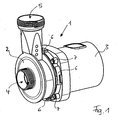
- a housing 1 which consists essentially of a pump housing part 2 and a motor housing part 3.
- the pump housing part 2 has a suction opening 4 and an outlet opening 5 for the water to be pumped.
- the two housing parts 2, 3 are connected to each other in a simple manner, for example, as shown by a bayonet connection 6 with additional screw 7.
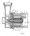
- the inside of the pump is in Fig. 2 shown in section.
- an impeller 8 is arranged on a preferably made of ceramic shaft 9 in the pump housing part 2, which is rotatably driven together with the shaft 9 by a motor housing 3 arranged electronically commutated motor (EC motor).
- EC motor electronically commutated motor
- the shaft 9 extends from the pump housing part 2 in the motor housing part 3 into it, wherein the motor is mechanically shielded by the impeller 8 by a bearing plate 10.
- the motor consists essentially of a fixed laminated stator core 12, on which also fixed coils 13 are accommodated, and a rotor 14, which is advantageously designed in the illustrated embodiment as a two-pole permanent magnet. Between rotor 14 and shaft 9 is fixedly connected to both parts a preferably solid and closed iron ring 15, which increases the magnetic flux of the motor noticeably.
- a circuit board 16 is arranged, which includes the entire control electronics.
- the motor has a ground contact 17 on the stator 12 and a Erdungsbelch 18 on the rear side of the motor housing part.
- the rotor 14 For sealing the water-carrying housing part 2 relative to the electrical components receiving housing part 3, the rotor 14 with all moving parts and the 12 with all current-carrying parts separated from each other by a rotor 14 surrounding the can 19.
- the can 19 widens with a large collar-like flange 19 'for complete separation between the pump housing part 2 and the motor housing part 3.
- the interior of the entire motor housing part 3 is filled with all free spaces, e.g. with synthetic resin.
- the potting compound 20 thus encloses the entire control electronics 16, so that it is not only protected against moisture, but also mechanically against vibration.
- the potting compound 20 also supports the can 19, and this can be inexpensively made of externally unreinforced plastic.
- the control electronics 16 may include a signal evaluation unit, not shown, are used by the received signals for speed control of the pump motor.
- the control signals can be directly modulated onto the mains voltage transmitted to the motor. This eliminates the need for a complex phase control gate for speed control of the pump, as it must be used for conventional engines so far.
- the operation for speed control can be done in particular via an activatable via a remote adapter plug, which is mounted between the mains and the power supply cable for the pump.
- This intermediate spacer includes a Reception module that receives the signals emitted by the remote control to change the engine speed. In the intermediate plug element these signals are then modulated onto the mains voltage and thereby passed on to the control electronics of the pump.
- the intermediate connector element thus assumes only the role of signal transmission, so that no power electronics is required.
- the stator 12 and the associated coils 13 are preferably designed such that the coils 13 can be pushed onto stator poles 22 of the stator 12 during assembly from the inside.
- This and the structure of the stator 12 with the coils 13 is in the Fig. 3 to 5 shown in more detail.
- By pushing the bobbin 13 eliminates the need to use expensive Einziehmaschinen for winding the coils, as is necessary in other one-piece laminations with pole shoes formed on the inside.
- the stator poles 22 of the stator 12 of the pump according to the invention are therefore on the inside substantially without broadening form, so that the sliding of the coil 13 is possible.
- the length a of the coils 13 must be both smaller than the minimum distance A1 of two opposite Polinnencare and smaller than the length A2 of the individual stator poles 22.
- the width b of the coil 13 must be less than the minimum distance B1 of two Polinnenkanten 42 respectively next pole 22, ie, between which exactly another stator 22 is located.
- the width b of the coil 13 must also be smaller than the minimum distance B2 of two coil outer edges in the installed state, between which in turn another coil 13th or another stator pole 22 is located.
- the width c of the stator poles 22 is smaller than the inner width C of the coils 13 to choose.
- the pump according to the invention is optimized so that on the one hand their dimensions should be as small as possible, but on the other hand, their efficiency as high as possible, and with improved ease of installation.
- the geometry ratios must be selected so that the coils 13 on the one hand can still be postponed and on the other hand, as many windings on the coils 13 can be accommodated.
- an arc length BL of the stator poles 22 is to be defined. If one accommodated inside the stator 12, in which the rotor rotates 14, a maximum large imaginary circle that touches the Statorpolinnencia 32 exactly, the sum of the arc lengths BL of all poles 22 could correspond exactly to half the circumference of the defined circle. In favor of the amount of copper to be accommodated on the coil windings and to avoid flux scattering, however, the arc length BL of each pole 22 is preferably reduced by approximately 11% to 12% compared with the just defined original length.
- an angle ⁇ between two extending from the stator center, the Polinnenkanten 42 of Statorpols tangent straight line 50 are given, the approximately 0.88 times 360 ° divided by the number n of the stator poles 22 and about 0.89 times 360 ° divided by the number n of the stator poles 22 is located.
- the coils 13 in the in Fig. 3 shown opening ds introduced and then pushed to the stop on the pole 22.
- the stator 12 of the illustrated embodiment has exactly six poles 22. Depending on the requirement, it is also possible to use the motor with a stator 12 with three, nine, to equip twelve, fifteen, etc. Poles. However, with more than six poles 22, the distances for the windings of the coils 13 become very narrow, so that the assembly and cost increases. A three-pole motor, however, has a reduced efficiency.
- the pump according to the invention is characterized by high ease of assembly, low production costs, high efficiency and optimized ease of use. It is not prone to repair and therefore almost maintenance-free. Due to their high efficiency and the reduced cost of materials, the energy consumption is minimized both in the production and in the operation of such a pump.
Landscapes
- Engineering & Computer Science (AREA)
- Power Engineering (AREA)
- Mechanical Engineering (AREA)
- General Engineering & Computer Science (AREA)
- Structures Of Non-Positive Displacement Pumps (AREA)
- Connection Of Motors, Electrical Generators, Mechanical Devices, And The Like (AREA)
- Iron Core Of Rotating Electric Machines (AREA)
- Physical Water Treatments (AREA)
- Water Treatment By Sorption (AREA)
- Farming Of Fish And Shellfish (AREA)
Claims (7)
- Pompe à eau pour des étangs ou similaires, avec un carter (1) qui comporte une partie de carter de pompe (2) présentant une ouverture d'aspiration (4) et une ouverture de sortie (5), dans laquelle est disposée de manière rotative une roue de roulement (8) avec un arbre (9), et une partie de carter de moteur (3), dans laquelle est reçu un moteur électrique à commutation électronique avec un stator (12) doté de plusieurs bobines (13) disposées sur des pôles du stator (22) et un rotor (14) tournant dans celui-ci, le stator (12) se composant d'un paquet de coupes de tôle respectivement d'un seul tenant et le rotor (14) réalisé comme un aimant permanent bipolaire et le stator (12) étant séparés l'un de l'autre par une gaine (19), caractérisée en ce que les pôles de stator (22) réalisés côté intérieur essentiellement sans élargissement présentent respectivement des bobines (13) poussées depuis le côté intérieur du stator (12), en ce que ces composants sont disposés conjointement avec une électronique de commande (16) pour le moteur dans la partie de carter de moteur (3) et en ce que dans celui-ci, le stator (12) avec les bobines (13) ainsi qu'avec l'électronique de commande (16) est coulé de manière étanche à l'eau de telle manière que l'intérieur de la partie de carter de moteur (3) entière est pourvue de masse de remplissage (20) remplissant tous les interstices.
- Pompe à eau selon la revendication 1, caractérisée en ce que la gaine (19) se compose de matière plastique non renforcée extérieurement.
- Pompe à eau selon la revendication 1 ou 2, caractérisée en ce qu'un anneau en fer (15) massif, au moins essentiellement fermé est disposé entre le rotor (14) et l'arbre (9).
- Pompe à eau selon l'une quelconque des revendications 1 à 3, caractérisée en ce que l'électronique de commande (16) comporte une unité d'évaluation des signaux qui évalue des signaux modulés sur la tension de réseau reçue et les utilise pour réguler le régime du moteur de la pompe.
- Pompe à eau selon l'une quelconque des revendications 1 à 4, caractérisée en ce que pour le stator (12) et les bobines (13) s'appliquent les conditions géométriques suivantes :


avec :a = longueur des bobines (13),A1 = distance minimale entre deux côtés intérieurs de pôle opposés (32),A2 = longueur des pôles de stator (22),b = largeur des bobines (13),B1 = distance minimale entre deux arêtes intérieures de pôle, entre lesquelles se trouve précisément un autre pôle de stator (22),B2 = distance minimale entre deux arêtes extérieures de bobine à l'état intégré, entre lesquelles se trouve précisément une autre bobine (13),c = largeur des pôles de stator (22),C = largeur intérieure des bobines (13). - Pompe à eau selon l'une quelconque des revendications 1 à 5, caractérisée en ce que la longueur intérieure de l'arc (BL) d'un pôle de stator (32) est réduite d'environ 11% à 12 % par rapport à une circonférence touchant les côtés intérieurs de pôle de stator (32), divisée par le nombre double de pôles de stator (22).
- Pompe à eau selon l'une quelconque des revendications 1 à 6, caractérisée en ce que pour le stator (12) s'applique par exemple la condition géométrique suivante :

avecα = angle entre deux droites (50) tangentes aux arêtes intérieures (42) d'un pôle de stator (22), s'étendant à partir du milieu du stator,n = nombre de pôles de stator (22).
Applications Claiming Priority (1)
| Application Number | Priority Date | Filing Date | Title |
|---|---|---|---|
| DE102006027001A DE102006027001A1 (de) | 2006-06-08 | 2006-06-08 | Wasserpumpe für insbesondere Teiche, Aquarien, Springbrunnen und dergleichen |
Publications (3)
| Publication Number | Publication Date |
|---|---|
| EP1865202A2 EP1865202A2 (fr) | 2007-12-12 |
| EP1865202A3 EP1865202A3 (fr) | 2008-06-04 |
| EP1865202B1 true EP1865202B1 (fr) | 2010-08-11 |
Family
ID=38430477
Family Applications (1)
| Application Number | Title | Priority Date | Filing Date |
|---|---|---|---|
| EP07009460A Active EP1865202B1 (fr) | 2006-06-08 | 2007-05-11 | Pompe à eau pour étangs, aquariums, fontaines et analogues |
Country Status (7)
| Country | Link |
|---|---|
| US (1) | US20070286752A1 (fr) |
| EP (1) | EP1865202B1 (fr) |
| CN (1) | CN101086260B (fr) |
| AT (1) | ATE477420T1 (fr) |
| CA (1) | CA2591191C (fr) |
| DE (2) | DE102006027001A1 (fr) |
| ES (1) | ES2349154T3 (fr) |
Families Citing this family (15)
| Publication number | Priority date | Publication date | Assignee | Title |
|---|---|---|---|---|
| DE102009023231B4 (de) * | 2009-05-29 | 2021-05-06 | Brose Fahrzeugteile SE & Co. Kommanditgesellschaft, Würzburg | Stator für einen Elektromotor |
| WO2011022483A1 (fr) * | 2009-08-18 | 2011-02-24 | Itt Manufacturing Enterprises, Inc. | Pompe submersible encapsulée |
| US9016290B2 (en) | 2011-02-24 | 2015-04-28 | Joseph E. Kovarik | Apparatus for removing a layer of sediment which has settled on the bottom of a pond |
| DE102012209487A1 (de) * | 2012-06-05 | 2013-12-05 | Mahle International Gmbh | Hydrodynamische Pumpe |
| US9130413B2 (en) * | 2012-07-25 | 2015-09-08 | Nidec Motor Corporation | Electric motor having a partially sealed housing |
| DE102012222359A1 (de) * | 2012-12-05 | 2014-06-05 | Mahle International Gmbh | Elektrische Flüssigkeitspumpe |
| DE102012222358A1 (de) * | 2012-12-05 | 2014-06-05 | Mahle International Gmbh | Elektrische Flüssigkeitspumpe |
| DE202016103632U1 (de) | 2016-07-07 | 2016-07-29 | Michael Rupp | Ansaugpumpe |
| US20190128267A1 (en) * | 2016-07-29 | 2019-05-02 | RELIAX MOTORES SA de CV | Integrated electric motor and fluid pump |
| DE102017220157B4 (de) * | 2017-11-13 | 2025-02-06 | Hanon Systems Efp Deutschland Gmbh | Wasserpumpe und Verfahren zur Herstellung einer Wasserpumpe |
| CN108271728B (zh) * | 2018-02-06 | 2023-12-05 | 广东博宇集团有限公司 | 一种水族箱 |
| US11168690B2 (en) * | 2019-04-11 | 2021-11-09 | Schaeffler Technologies AG & Co. KG | Integrated motor and pump including axially placed coils |
| CN112354927B (zh) * | 2020-03-29 | 2021-09-07 | 苏州市臻湖流体技术有限公司 | 一种智能清洗直线泵 |
| CN112392779A (zh) * | 2020-11-27 | 2021-02-23 | 临城清泉水泵制造有限公司 | 一种高效节能型潜水电泵 |
| CN114109847B (zh) * | 2021-11-29 | 2024-03-19 | 汉江弘源襄阳碳化硅特种陶瓷有限责任公司 | 一种复合材料渣浆泵泵体及其制造方法 |
Family Cites Families (23)
| Publication number | Priority date | Publication date | Assignee | Title |
|---|---|---|---|---|
| US3791773A (en) * | 1972-06-09 | 1974-02-12 | Little Giant Corp | Submersible pump |
| DE3245973A1 (de) * | 1982-12-11 | 1984-06-14 | Allweiler Ag, 7760 Radolfzell | Motorpumpenaggregat |
| US4679313A (en) * | 1985-03-08 | 1987-07-14 | Kollmorgen Technologies Corporation | Method of making a servo motor with high energy product magnets |
| US4998865A (en) * | 1988-07-11 | 1991-03-12 | Aisan Kogyo Kabushiki Kaisha | Brushless DC pump with enclosed circuit board |
| US5096390A (en) * | 1990-10-16 | 1992-03-17 | Micropump Corporation | Pump assembly with integral electronically commutated drive system |
| GB2258765B (en) * | 1991-06-27 | 1996-01-10 | Dana Corp | Variable reluctance motor having foil wire wound coils |
| IT1259848B (it) * | 1992-11-27 | 1996-03-28 | Hydor Srl | Motore elettrico sincrono, particolarmente per pompe immergibili e pompa incorporante tale motore |
| DE4301675A1 (de) * | 1993-01-22 | 1994-07-28 | Pierburg Gmbh | Elektronisch kommutierter Elektromotor |
| DE4434448C2 (de) * | 1994-09-27 | 1996-10-17 | Richard Halm | Naßläufer-Spaltrohrmotor für Pumpen |
| DE4438130A1 (de) * | 1994-10-27 | 1996-05-02 | Wilo Gmbh | Spaltrohrmotor |
| US6065946A (en) * | 1997-07-03 | 2000-05-23 | Servo Magnetics, Inc. | Integrated controller pump |
| DE19943862A1 (de) * | 1999-09-13 | 2001-03-15 | Wilo Gmbh | Naßläuferpumpe mit Montageplatte |
| JP3752594B2 (ja) * | 2000-04-25 | 2006-03-08 | 愛三工業株式会社 | 磁気結合ポンプ |
| DE10052797A1 (de) * | 2000-10-25 | 2002-05-08 | Bosch Gmbh Robert | Elektromotorisch angetriebene Pumpe und Verfahren zur Herstellung einer solchen Pumpe |
| EP1348864A4 (fr) * | 2001-01-05 | 2005-03-16 | Hitachi Ltd | Pompe d'alimentation en carburant haute pression |
| JP2002213385A (ja) * | 2001-01-19 | 2002-07-31 | Ebara Corp | キャンドモータ及びキャンドモータポンプ |
| US6821416B1 (en) * | 2002-09-19 | 2004-11-23 | Aquascape Designs, Inc. | Pond system and related pump |
| US20050063843A1 (en) * | 2003-09-18 | 2005-03-24 | Beckett Corporation | Submersible pump |
| JP4565870B2 (ja) * | 2004-03-26 | 2010-10-20 | ミネベア株式会社 | 電動ポンプ |
| US7474024B2 (en) * | 2004-09-15 | 2009-01-06 | Aisan Kogyo Kabushiki Kaisha | Electronic control unit and electric pump |
| DE102004056303A1 (de) * | 2004-11-22 | 2006-06-01 | Minebea Co., Ltd. | Statoranrordnung für eine elektrische Maschine, Verfahren zur Herstellung einer Statoranordnung und Gleichstrommotor |
| KR20080016863A (ko) * | 2005-05-17 | 2008-02-22 | 페더럴-모걸 코오포레이숀 | Bldc 모터 및 캡슐화된 회로 보드를 가진 펌프어셈블리 |
| DE102007016255B4 (de) * | 2006-04-28 | 2012-11-29 | Bühler Motor GmbH | Kreiselpumpe |
-
2006
- 2006-06-08 DE DE102006027001A patent/DE102006027001A1/de not_active Withdrawn
-
2007
- 2007-05-11 ES ES07009460T patent/ES2349154T3/es active Active
- 2007-05-11 AT AT07009460T patent/ATE477420T1/de active
- 2007-05-11 EP EP07009460A patent/EP1865202B1/fr active Active
- 2007-05-11 DE DE502007004689T patent/DE502007004689D1/de active Active
- 2007-06-07 CA CA2591191A patent/CA2591191C/fr active Active
- 2007-06-08 CN CN2007101102110A patent/CN101086260B/zh active Active
- 2007-06-08 US US11/760,045 patent/US20070286752A1/en not_active Abandoned
Also Published As
| Publication number | Publication date |
|---|---|
| ATE477420T1 (de) | 2010-08-15 |
| EP1865202A2 (fr) | 2007-12-12 |
| CN101086260B (zh) | 2012-04-04 |
| DE502007004689D1 (de) | 2010-09-23 |
| ES2349154T3 (es) | 2010-12-28 |
| EP1865202A3 (fr) | 2008-06-04 |
| CN101086260A (zh) | 2007-12-12 |
| CA2591191A1 (fr) | 2007-12-08 |
| US20070286752A1 (en) | 2007-12-13 |
| CA2591191C (fr) | 2015-01-27 |
| DE102006027001A1 (de) | 2007-12-13 |
Similar Documents
| Publication | Publication Date | Title |
|---|---|---|
| EP1865202A2 (fr) | Pompe à eau en particulier pour étangs, aquariums, fontaines et analogues | |
| DE102006034991B4 (de) | Elektrische Servolenkungsvorrichtung | |
| DE102010019502B4 (de) | Pumpe mit integriertem elektronisch kommutierten Gleichstrommotor | |
| EP2302219B1 (fr) | Unité de pompage | |
| DE112017002406B4 (de) | Antriebsvorrichtung und Pumpvorrichtung | |
| EP3078099B1 (fr) | Stator pour moteur à courant continu à commutation électronique | |
| DE102008000124A1 (de) | Kompressor, insbesondere elektromotorisch angetriebener Kompressor | |
| EP2500575A1 (fr) | Pompe de recirculation de chauffage | |
| DE102016202463A1 (de) | Elektronische Steuervorrichtung, Motorsteuervorrichtung und elektrische Fluidpumpe | |
| WO2008086879A1 (fr) | Groupe motopompe | |
| WO2012123238A1 (fr) | Pompe de circulation de chauffage | |
| EP2607707A1 (fr) | Moteur électrique | |
| DE102013020094A1 (de) | Elektromotor, insbesondere Kühlerlüftermotor | |
| DE102004050373A1 (de) | Statoranordnung für eine elektrische Maschine und Elektromotor | |
| DE4310226A1 (de) | Mittels Permanentmagneten erregter elektrischer Motor | |
| DE102004050374B4 (de) | Elektrische Maschine, insbesondere Gleichstrommotor | |
| DE102017222754A1 (de) | Gerotor Pumpe | |
| DE102008064132A1 (de) | Elektrische Maschine | |
| EP3394960B1 (fr) | Pompe centrifuge, notamment pompe de circulation | |
| EP3940242A1 (fr) | Turbomachine ayant des câbles de raccordement encapsulés dans une résine | |
| EP3391509B1 (fr) | Moteur électrique | |
| DE102007021917A1 (de) | Elektrische Maschine mit verbesserter Wärmeabfuhr | |
| EP1420503B1 (fr) | Carcasse d'un moteur | |
| EP1691468B1 (fr) | Unité de pompage | |
| EP0713282B1 (fr) | Moteur à manchon d'entrefer |
Legal Events
| Date | Code | Title | Description |
|---|---|---|---|
| PUAI | Public reference made under article 153(3) epc to a published international application that has entered the european phase |
Free format text: ORIGINAL CODE: 0009012 |
|
| AK | Designated contracting states |
Kind code of ref document: A2 Designated state(s): AT BE BG CH CY CZ DE DK EE ES FI FR GB GR HU IE IS IT LI LT LU LV MC MT NL PL PT RO SE SI SK TR |
|
| AX | Request for extension of the european patent |
Extension state: AL BA HR MK YU |
|
| PUAL | Search report despatched |
Free format text: ORIGINAL CODE: 0009013 |
|
| AK | Designated contracting states |
Kind code of ref document: A3 Designated state(s): AT BE BG CH CY CZ DE DK EE ES FI FR GB GR HU IE IS IT LI LT LU LV MC MT NL PL PT RO SE SI SK TR |
|
| AX | Request for extension of the european patent |
Extension state: AL BA HR MK RS |
|
| 17P | Request for examination filed |
Effective date: 20081125 |
|
| 17Q | First examination report despatched |
Effective date: 20090112 |
|
| AKX | Designation fees paid |
Designated state(s): AT BE BG CH CY CZ DE DK EE ES FI FR GB GR HU IE IS IT LI LT LU LV MC MT NL PL PT RO SE SI SK TR |
|
| GRAP | Despatch of communication of intention to grant a patent |
Free format text: ORIGINAL CODE: EPIDOSNIGR1 |
|
| RTI1 | Title (correction) |
Free format text: WATER PUMP FOR PONDS, AQUARIUMS, FOUNTAINS AND SIMILAR |
|
| GRAS | Grant fee paid |
Free format text: ORIGINAL CODE: EPIDOSNIGR3 |
|
| GRAA | (expected) grant |
Free format text: ORIGINAL CODE: 0009210 |
|
| AK | Designated contracting states |
Kind code of ref document: B1 Designated state(s): AT BE BG CH CY CZ DE DK EE ES FI FR GB GR HU IE IS IT LI LT LU LV MC MT NL PL PT RO SE SI SK TR |
|
| REG | Reference to a national code |
Ref country code: GB Ref legal event code: FG4D Free format text: NOT ENGLISH |
|
| REG | Reference to a national code |
Ref country code: CH Ref legal event code: EP |
|
| REG | Reference to a national code |
Ref country code: IE Ref legal event code: FG4D Free format text: LANGUAGE OF EP DOCUMENT: GERMAN |
|
| REF | Corresponds to: |
Ref document number: 502007004689 Country of ref document: DE Date of ref document: 20100923 Kind code of ref document: P |
|
| REG | Reference to a national code |
Ref country code: NL Ref legal event code: T3 |
|
| REG | Reference to a national code |
Ref country code: ES Ref legal event code: FG2A Effective date: 20101215 |
|
| LTIE | Lt: invalidation of european patent or patent extension |
Effective date: 20100811 |
|
| PG25 | Lapsed in a contracting state [announced via postgrant information from national office to epo] |
Ref country code: FI Free format text: LAPSE BECAUSE OF FAILURE TO SUBMIT A TRANSLATION OF THE DESCRIPTION OR TO PAY THE FEE WITHIN THE PRESCRIBED TIME-LIMIT Effective date: 20100811 Ref country code: LT Free format text: LAPSE BECAUSE OF FAILURE TO SUBMIT A TRANSLATION OF THE DESCRIPTION OR TO PAY THE FEE WITHIN THE PRESCRIBED TIME-LIMIT Effective date: 20100811 |
|
| PG25 | Lapsed in a contracting state [announced via postgrant information from national office to epo] |
Ref country code: SI Free format text: LAPSE BECAUSE OF FAILURE TO SUBMIT A TRANSLATION OF THE DESCRIPTION OR TO PAY THE FEE WITHIN THE PRESCRIBED TIME-LIMIT Effective date: 20100811 Ref country code: PT Free format text: LAPSE BECAUSE OF FAILURE TO SUBMIT A TRANSLATION OF THE DESCRIPTION OR TO PAY THE FEE WITHIN THE PRESCRIBED TIME-LIMIT Effective date: 20101213 Ref country code: PL Free format text: LAPSE BECAUSE OF FAILURE TO SUBMIT A TRANSLATION OF THE DESCRIPTION OR TO PAY THE FEE WITHIN THE PRESCRIBED TIME-LIMIT Effective date: 20100811 Ref country code: BG Free format text: LAPSE BECAUSE OF FAILURE TO SUBMIT A TRANSLATION OF THE DESCRIPTION OR TO PAY THE FEE WITHIN THE PRESCRIBED TIME-LIMIT Effective date: 20101111 Ref country code: CY Free format text: LAPSE BECAUSE OF FAILURE TO SUBMIT A TRANSLATION OF THE DESCRIPTION OR TO PAY THE FEE WITHIN THE PRESCRIBED TIME-LIMIT Effective date: 20100811 Ref country code: IS Free format text: LAPSE BECAUSE OF FAILURE TO SUBMIT A TRANSLATION OF THE DESCRIPTION OR TO PAY THE FEE WITHIN THE PRESCRIBED TIME-LIMIT Effective date: 20101211 |
|
| REG | Reference to a national code |
Ref country code: IE Ref legal event code: FD4D |
|
| PG25 | Lapsed in a contracting state [announced via postgrant information from national office to epo] |
Ref country code: SE Free format text: LAPSE BECAUSE OF FAILURE TO SUBMIT A TRANSLATION OF THE DESCRIPTION OR TO PAY THE FEE WITHIN THE PRESCRIBED TIME-LIMIT Effective date: 20100811 Ref country code: GR Free format text: LAPSE BECAUSE OF FAILURE TO SUBMIT A TRANSLATION OF THE DESCRIPTION OR TO PAY THE FEE WITHIN THE PRESCRIBED TIME-LIMIT Effective date: 20101112 Ref country code: LV Free format text: LAPSE BECAUSE OF FAILURE TO SUBMIT A TRANSLATION OF THE DESCRIPTION OR TO PAY THE FEE WITHIN THE PRESCRIBED TIME-LIMIT Effective date: 20100811 |
|
| PG25 | Lapsed in a contracting state [announced via postgrant information from national office to epo] |
Ref country code: IE Free format text: LAPSE BECAUSE OF FAILURE TO SUBMIT A TRANSLATION OF THE DESCRIPTION OR TO PAY THE FEE WITHIN THE PRESCRIBED TIME-LIMIT Effective date: 20100811 Ref country code: DK Free format text: LAPSE BECAUSE OF FAILURE TO SUBMIT A TRANSLATION OF THE DESCRIPTION OR TO PAY THE FEE WITHIN THE PRESCRIBED TIME-LIMIT Effective date: 20100811 |
|
| PG25 | Lapsed in a contracting state [announced via postgrant information from national office to epo] |
Ref country code: RO Free format text: LAPSE BECAUSE OF FAILURE TO SUBMIT A TRANSLATION OF THE DESCRIPTION OR TO PAY THE FEE WITHIN THE PRESCRIBED TIME-LIMIT Effective date: 20100811 Ref country code: SK Free format text: LAPSE BECAUSE OF FAILURE TO SUBMIT A TRANSLATION OF THE DESCRIPTION OR TO PAY THE FEE WITHIN THE PRESCRIBED TIME-LIMIT Effective date: 20100811 Ref country code: EE Free format text: LAPSE BECAUSE OF FAILURE TO SUBMIT A TRANSLATION OF THE DESCRIPTION OR TO PAY THE FEE WITHIN THE PRESCRIBED TIME-LIMIT Effective date: 20100811 Ref country code: CZ Free format text: LAPSE BECAUSE OF FAILURE TO SUBMIT A TRANSLATION OF THE DESCRIPTION OR TO PAY THE FEE WITHIN THE PRESCRIBED TIME-LIMIT Effective date: 20100811 |
|
| PLBE | No opposition filed within time limit |
Free format text: ORIGINAL CODE: 0009261 |
|
| STAA | Information on the status of an ep patent application or granted ep patent |
Free format text: STATUS: NO OPPOSITION FILED WITHIN TIME LIMIT |
|
| 26N | No opposition filed |
Effective date: 20110512 |
|
| REG | Reference to a national code |
Ref country code: DE Ref legal event code: R097 Ref document number: 502007004689 Country of ref document: DE Effective date: 20110512 |
|
| PG25 | Lapsed in a contracting state [announced via postgrant information from national office to epo] |
Ref country code: MT Free format text: LAPSE BECAUSE OF FAILURE TO SUBMIT A TRANSLATION OF THE DESCRIPTION OR TO PAY THE FEE WITHIN THE PRESCRIBED TIME-LIMIT Effective date: 20100811 Ref country code: MC Free format text: LAPSE BECAUSE OF NON-PAYMENT OF DUE FEES Effective date: 20110531 |
|
| REG | Reference to a national code |
Ref country code: CH Ref legal event code: PL |
|
| PG25 | Lapsed in a contracting state [announced via postgrant information from national office to epo] |
Ref country code: CH Free format text: LAPSE BECAUSE OF NON-PAYMENT OF DUE FEES Effective date: 20110531 Ref country code: LI Free format text: LAPSE BECAUSE OF NON-PAYMENT OF DUE FEES Effective date: 20110531 |
|
| PG25 | Lapsed in a contracting state [announced via postgrant information from national office to epo] |
Ref country code: LU Free format text: LAPSE BECAUSE OF NON-PAYMENT OF DUE FEES Effective date: 20110511 |
|
| REG | Reference to a national code |
Ref country code: AT Ref legal event code: MM01 Ref document number: 477420 Country of ref document: AT Kind code of ref document: T Effective date: 20120511 |
|
| PG25 | Lapsed in a contracting state [announced via postgrant information from national office to epo] |
Ref country code: AT Free format text: LAPSE BECAUSE OF NON-PAYMENT OF DUE FEES Effective date: 20120511 |
|
| PG25 | Lapsed in a contracting state [announced via postgrant information from national office to epo] |
Ref country code: TR Free format text: LAPSE BECAUSE OF FAILURE TO SUBMIT A TRANSLATION OF THE DESCRIPTION OR TO PAY THE FEE WITHIN THE PRESCRIBED TIME-LIMIT Effective date: 20100811 |
|
| PG25 | Lapsed in a contracting state [announced via postgrant information from national office to epo] |
Ref country code: HU Free format text: LAPSE BECAUSE OF FAILURE TO SUBMIT A TRANSLATION OF THE DESCRIPTION OR TO PAY THE FEE WITHIN THE PRESCRIBED TIME-LIMIT Effective date: 20100811 |
|
| REG | Reference to a national code |
Ref country code: FR Ref legal event code: PLFP Year of fee payment: 10 |
|
| REG | Reference to a national code |
Ref country code: FR Ref legal event code: PLFP Year of fee payment: 11 |
|
| REG | Reference to a national code |
Ref country code: FR Ref legal event code: PLFP Year of fee payment: 12 |
|
| PGFP | Annual fee paid to national office [announced via postgrant information from national office to epo] |
Ref country code: NL Payment date: 20240522 Year of fee payment: 18 |
|
| PGFP | Annual fee paid to national office [announced via postgrant information from national office to epo] |
Ref country code: GB Payment date: 20240522 Year of fee payment: 18 |
|
| PGFP | Annual fee paid to national office [announced via postgrant information from national office to epo] |
Ref country code: DE Payment date: 20240517 Year of fee payment: 18 |
|
| PGFP | Annual fee paid to national office [announced via postgrant information from national office to epo] |
Ref country code: ES Payment date: 20240614 Year of fee payment: 18 |
|
| PGFP | Annual fee paid to national office [announced via postgrant information from national office to epo] |
Ref country code: FR Payment date: 20240523 Year of fee payment: 18 |
|
| PGFP | Annual fee paid to national office [announced via postgrant information from national office to epo] |
Ref country code: BE Payment date: 20240521 Year of fee payment: 18 |
|
| PGFP | Annual fee paid to national office [announced via postgrant information from national office to epo] |
Ref country code: IT Payment date: 20240531 Year of fee payment: 18 |
|
| REG | Reference to a national code |
Ref country code: DE Ref legal event code: R119 Ref document number: 502007004689 Country of ref document: DE |
|
| REG | Reference to a national code |
Ref country code: NL Ref legal event code: MM Effective date: 20250601 |
|
| GBPC | Gb: european patent ceased through non-payment of renewal fee |
Effective date: 20250511 |
|
| REG | Reference to a national code |
Ref country code: BE Ref legal event code: MM Effective date: 20250531 |
|
| PG25 | Lapsed in a contracting state [announced via postgrant information from national office to epo] |
Ref country code: NL Free format text: LAPSE BECAUSE OF NON-PAYMENT OF DUE FEES Effective date: 20250601 |
|
| PG25 | Lapsed in a contracting state [announced via postgrant information from national office to epo] |
Ref country code: GB Free format text: LAPSE BECAUSE OF NON-PAYMENT OF DUE FEES Effective date: 20250511 |
|
| PG25 | Lapsed in a contracting state [announced via postgrant information from national office to epo] |
Ref country code: DE Free format text: LAPSE BECAUSE OF NON-PAYMENT OF DUE FEES Effective date: 20251202 |
|
| PG25 | Lapsed in a contracting state [announced via postgrant information from national office to epo] |
Ref country code: BE Free format text: LAPSE BECAUSE OF NON-PAYMENT OF DUE FEES Effective date: 20250531 Ref country code: IT Free format text: LAPSE BECAUSE OF NON-PAYMENT OF DUE FEES Effective date: 20250511 |
|
| PG25 | Lapsed in a contracting state [announced via postgrant information from national office to epo] |
Ref country code: FR Free format text: LAPSE BECAUSE OF NON-PAYMENT OF DUE FEES Effective date: 20250531 |