EP1865222A1 - Dispositif de pendule à force centrifuge - Google Patents
Dispositif de pendule à force centrifuge Download PDFInfo
- Publication number
- EP1865222A1 EP1865222A1 EP07010299A EP07010299A EP1865222A1 EP 1865222 A1 EP1865222 A1 EP 1865222A1 EP 07010299 A EP07010299 A EP 07010299A EP 07010299 A EP07010299 A EP 07010299A EP 1865222 A1 EP1865222 A1 EP 1865222A1
- Authority
- EP
- European Patent Office
- Prior art keywords
- pendulum
- pendulum mass
- centrifugal
- centrifugal pendulum
- end portions
- Prior art date
- Legal status (The legal status is an assumption and is not a legal conclusion. Google has not performed a legal analysis and makes no representation as to the accuracy of the status listed.)
- Withdrawn
Links
- 230000005540 biological transmission Effects 0.000 claims abstract description 15
- 238000002485 combustion reaction Methods 0.000 claims abstract description 4
- 238000013016 damping Methods 0.000 claims description 6
- 230000003750 conditioning effect Effects 0.000 claims 1
- 230000008878 coupling Effects 0.000 description 3
- 238000010168 coupling process Methods 0.000 description 3
- 238000005859 coupling reaction Methods 0.000 description 3
- 229920001971 elastomer Polymers 0.000 description 2
- 239000000463 material Substances 0.000 description 2
- 230000001419 dependent effect Effects 0.000 description 1
- 239000000806 elastomer Substances 0.000 description 1
Images
Classifications
-
- F—MECHANICAL ENGINEERING; LIGHTING; HEATING; WEAPONS; BLASTING
- F16—ENGINEERING ELEMENTS AND UNITS; GENERAL MEASURES FOR PRODUCING AND MAINTAINING EFFECTIVE FUNCTIONING OF MACHINES OR INSTALLATIONS; THERMAL INSULATION IN GENERAL
- F16F—SPRINGS; SHOCK-ABSORBERS; MEANS FOR DAMPING VIBRATION
- F16F15/00—Suppression of vibrations in systems; Means or arrangements for avoiding or reducing out-of-balance forces, e.g. due to motion
- F16F15/10—Suppression of vibrations in rotating systems by making use of members moving with the system
- F16F15/14—Suppression of vibrations in rotating systems by making use of members moving with the system using masses freely rotating with the system, i.e. uninvolved in transmitting driveline torque, e.g. rotative dynamic dampers
- F16F15/1407—Suppression of vibrations in rotating systems by making use of members moving with the system using masses freely rotating with the system, i.e. uninvolved in transmitting driveline torque, e.g. rotative dynamic dampers the rotation being limited with respect to the driving means
- F16F15/145—Masses mounted with play with respect to driving means thus enabling free movement over a limited range
Definitions
- the invention relates to a centrifugal pendulum device with a pendulum mass support device to which a plurality of pendulum masses are mounted by means of rollers relative to the pendulum mass support means movable.
- the invention further relates to a torque transmission device in the drive train of a motor vehicle for torque transmission between a drive unit, in particular an internal combustion engine, with an output shaft, in particular a crankshaft, and with a transmission having at least one transmission input shaft and at least one coupling device and / or at least one torsional vibration damping device.
- the object of the invention is to optimize a centrifugal pendulum device according to the preamble of claim 1, in particular with regard to the noise occurring during operation.
- the problem is solved in a centrifugal pendulum device with a pendulum mass support device to which a plurality of pendulum masses by means of rollers relative to the pendulum mass support means are movable, achieved in that the rollers are equipped with at least one O-ring, which comes to an associated pendulum mass to the plant ,
- the O-ring is formed of a resilient plastic material, in particular of an elastomer, such as rubber.
- a preferred embodiment of the centrifugal pendulum device is characterized in that the rollers each have a central portion which extends through the pendulum mass support means and extend from the two end portions, which are each equipped with an O-ring in mass pendulum masses.
- the end portions of the rollers are each guided on running surfaces which are formed in oblong holes of the pendulum masses.
- centrifugal pendulum device is characterized in that the O-rings are each arranged in an annular groove which in the end portions is provided.
- the annular groove is preferably arranged in each case in the vicinity of the free end of the associated end portion.
- a further preferred embodiment of the centrifugal pendulum device is characterized in that the outer diameter of the O-rings is greater than the outer diameter of the end portions. This ensures that the O-ring protrudes radially outward from the associated annular groove out.
- centrifugal pendulum device is characterized in that the outer diameter of the O-rings is larger by about 0.4 mm than the outer diameter of the end portions. This value is material-dependent and has proven to be particularly advantageous in the context of the present invention. A preferred range is between 0.2 and 0.6 mm.
- centrifugal pendulum device is characterized in that the thickness of the O-rings is greater than the depth of the associated annular grooves. This ensures that the O-rings protrude in the radial direction from the associated annular grooves.
- centrifugal pendulum device is characterized in that the annular grooves are arranged in the vicinity of the free ends of the end portions. It is essential that the annular grooves are arranged, at least partially, within associated through-holes, which are provided in the pendulum masses for the rollers.
- centrifugal pendulum device is characterized in that the rollers between the central portion and the end portions each have a collar which is arranged under centrifugal force on the pendulum mass in the axial direction between the pendulum mass and the pendulum mass support means.
- the collar has the function of preventing, during normal operation of the torque transmission device, that the pendulum masses do not come into contact with the pendulum mass carrier device.
- centrifugal pendulum device is characterized in that the collar tapers in the radial direction to the outside. Thereby Damage to the federal government and / or the pendulum mass carrier device are reliably prevented.
- a torque transmission device in the drive train of a motor vehicle for torque transmission between a drive unit, in particular an internal combustion engine, with an output shaft, in particular a crankshaft, and with a transmission having at least one transmission input shaft and at least one coupling device and / or with at least one torsional vibration damping device, the above Task solved by a previously described centrifugal pendulum device.
- the centrifugal pendulum device is preferably arranged between the coupling device and the torsional vibration damping device.
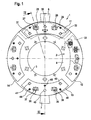
- a centrifugal pendulum device 1 according to an embodiment of the invention in plan view and in section is shown.
- the centrifugal pendulum device 1 comprises a pendulum mass carrier device 2, which essentially has the shape of a circular disk 4. From the annular disc 4, two diametrically arranged lugs 6, 7 extend radially outwards. The lugs 6, 7 have contact surfaces for (not shown) bow springs of a torsional vibration damping device.
- the pendulum mass support device 2 at the same time has the function of an output flange of a torsional vibration damping device and is therefore also referred to as a flange.
- the raceways 27, 28 are formed by through-holes, which extend in the axial direction through the pendulum mass 11 and have the shape of elongated holes which are curved kidney-shaped.
- To attach the pendulum masses 11, 21 on the pendulum mass carrier 2 further three stepped bolts 30 to 32 are provided. Within a dashed opening 33 it can be seen that in the annular disc 4 also kidney-shaped curved slots are formed for receiving the stepped bolt.
- the pendulum mass 13 is attached by means of rollers 35, 36 to the pendulum mass support means 2.
- the movement of the rollers 35, 36 is limited by raceways 37, 38.
- three stepped bolts 40 to 42 are provided.
- the rollers 35, 36 and the stepped bolts 40 to 42 serve to limit and define the movement of the pendulum masses 13, 23 in the plane of the drawing, ie in the radial direction and in the circumferential direction.
- each of the pendulum masses 13, 23 are still three axial thrust elements 44 to 46 attached.
- the axial thrust elements which are attached to the pendulum masses 13, 23, each having a bolt 48, 50 with a bolt head 49, 51, in the axial direction between the pendulum masses 13, 23 and the annular disc 4 of Pendulum mass support device 2 is arranged.
- the axial thrust elements 44 to 46 are preferably formed of plastic, and serve to reduce noise that occurs when the pendulum masses 13, 23 abut in the axial direction of the annular disc 4 of the pendulum mass support means 2.
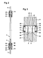
- the roller 25 extends through a through hole 54 which is recessed in the pendulum mass support device 2.
- the roller 25 has a center portion 60 disposed in the through hole 54. From the middle section 60, two end sections 61, 62 are assumed which have the same outside diameter as the center section 60.
- the sections 60 to 62 each have the shape of straight circular cylinders. Between the middle portion 60 and the end portion 61, 62 a collar 64, 65 is formed in each case.
- the collars 64, 65 taper radially outwards and have, inter alia, the function of preventing the torque transmission device during normal operation that the pendulum masses 11, 21 come into contact with the circular ring disk 4 of the pendulum mass support device 2.
- the end portions 61, 62 of the roller 25 are each equipped with a chamfer 68, 69 at their ends.
- annular groove 71, 72 is recessed in the associated end portion in each case.
- the annular grooves 71, 72 each have a rectangular cross-section.
- an O-ring 74, 75 is received in each case.
- the O-rings 74, 75 have a circular cross-section.
- the cross-section of the O-rings 74, 75 is slightly larger than the corresponding groove cross-section, so that the O-rings 74, 75 respectively project radially outward from the associated annular grooves 71, 72 out.
- the roller 25 which is also referred to as a cylindrical roller, provided at their ends with a respective groove.
- the O-rings 74, 75 mounted on the ends of the cylindrical roller 25 have a diameter which is about 0.4 mm larger than the running surface of the cylindrical roller 25 formed at the end portions. Under centrifugal force, the O-rings 74, 75 are compressed and the pressure occurring during operation passes over the running surface to the end portions 61, 62.
Landscapes
- Engineering & Computer Science (AREA)
- General Engineering & Computer Science (AREA)
- Physics & Mathematics (AREA)
- Acoustics & Sound (AREA)
- Aviation & Aerospace Engineering (AREA)
- Mechanical Engineering (AREA)
- Pulleys (AREA)
- Rolling Contact Bearings (AREA)
Applications Claiming Priority (1)
| Application Number | Priority Date | Filing Date | Title |
|---|---|---|---|
| DE102006026976 | 2006-06-10 |
Publications (1)
| Publication Number | Publication Date |
|---|---|
| EP1865222A1 true EP1865222A1 (fr) | 2007-12-12 |
Family
ID=38512235
Family Applications (1)
| Application Number | Title | Priority Date | Filing Date |
|---|---|---|---|
| EP07010299A Withdrawn EP1865222A1 (fr) | 2006-06-10 | 2007-05-24 | Dispositif de pendule à force centrifuge |
Country Status (2)
| Country | Link |
|---|---|
| EP (1) | EP1865222A1 (fr) |
| CN (1) | CN101086290A (fr) |
Cited By (8)
| Publication number | Priority date | Publication date | Assignee | Title |
|---|---|---|---|---|
| WO2009146673A1 (fr) * | 2008-06-02 | 2009-12-10 | Luk Lamellen Und Kupplungsbau Beteiligungs Kg | Amortisseur de vibrations de torsion avec pendule à force centrifuge |
| WO2009152800A1 (fr) * | 2008-06-16 | 2009-12-23 | Luk Lamellen Und Kupplungsbau Beteiligungs Kg | Double embrayage |
| WO2010118719A1 (fr) * | 2009-04-14 | 2010-10-21 | Schaeffler Technologies Gmbh & Co. Kg | Pendule à force centrifuge |
| US20120055281A1 (en) * | 2009-03-16 | 2012-03-08 | Schaeffler Technologies Gmbh & Co. Kg | Centrifugal force pendulum |
| US20130133476A1 (en) * | 2010-06-29 | 2013-05-30 | Schaeffler Technologies AG & Co. KG | Centrifugal force pendulum device |
| WO2013171032A1 (fr) * | 2012-05-16 | 2013-11-21 | Schaeffler Technologies AG & Co. KG | Galet pendulaire pour dispositif à pendule centrifuge et dispositif à pendule centrifuge comprenant un galet pendulaire dudit type |
| WO2016015725A1 (fr) * | 2014-07-28 | 2016-02-04 | Schaeffler Technologies AG & Co. KG | Pendule à force centrifuge |
| CN106170639A (zh) * | 2014-04-04 | 2016-11-30 | 丰田自动车株式会社 | 扭转振动降低装置 |
Families Citing this family (22)
| Publication number | Priority date | Publication date | Assignee | Title |
|---|---|---|---|---|
| DE202011004695U1 (de) * | 2010-08-19 | 2011-09-26 | Schaeffler Technologies Gmbh & Co. Kg | Fliehkraftpendeleinrichtung |
| EP2734746A1 (fr) * | 2011-07-18 | 2014-05-28 | Schaeffler Technologies GmbH & Co. KG | Système de ressorts en arc pour un volant bi-masse |
| CN103842686B (zh) * | 2011-09-19 | 2016-10-12 | 舍弗勒技术股份两合公司 | 离心力摆 |
| FR2982335B1 (fr) * | 2011-11-07 | 2013-11-22 | Valeo Embrayages | Dispositif de filtration de type oscillateur pendulaire comportant un systeme de guidage perfectionne |
| US9631696B2 (en) * | 2011-11-28 | 2017-04-25 | Schaeffler Technologies AG & Co. KG | Centrifugal force pendulum |
| DE102012221265B4 (de) * | 2011-12-07 | 2017-05-24 | Schaeffler Technologies AG & Co. KG | Fliehkraftpendel mit Dämpfer |
| DE102013202686A1 (de) * | 2012-03-16 | 2013-09-19 | Schaeffler Technologies AG & Co. KG | Reibungskupplung mit Fliehkraftpendel |
| EP2836739B1 (fr) * | 2012-04-13 | 2016-03-30 | Schaeffler Technologies AG & Co. KG | Dispositif de pendule centrifuge |
| FR2989753B1 (fr) | 2012-04-20 | 2014-04-18 | Valeo Embrayages | Dispositif d'amortissement pendulaire, en particulier pour une transmission de vehicule automobile |
| DE112013003577A5 (de) * | 2012-07-18 | 2015-04-16 | Schaeffler Technologies Gmbh & Co. Kg | Fliehkraftpendel |
| US9689463B2 (en) * | 2012-07-31 | 2017-06-27 | Schaeffler Technologies Gmbh & Co. Kg | Roller for a pendulum mass of a centrifugal force pendulum |
| FR2995953B1 (fr) * | 2012-09-24 | 2014-09-12 | Valeo Embrayages | Dispositif de transmission de couple pour un vehicule automobile |
| DE102012025327B4 (de) * | 2012-12-22 | 2017-03-30 | Audi Ag | Fliehkraftpendeleinrichtung sowie Antriebsstrang eines Kraftfahrzeugs |
| DE112014002294A5 (de) * | 2013-05-06 | 2016-02-04 | Schaeffler Technologies AG & Co. KG | Fliehkraftpendel |
| DE112014002737B4 (de) * | 2013-08-09 | 2021-02-04 | Aisin Aw Co., Ltd. | Zentrifugalpendel-Schwingungs-Absorbtionseinrichtung |
| DE102014219524A1 (de) * | 2013-10-09 | 2015-04-09 | Schaeffler Technologies AG & Co. KG | Dämpfungseinrichtung |
| WO2015149790A1 (fr) * | 2014-04-02 | 2015-10-08 | Schaeffler Technologies AG & Co. KG | Ensemble pendule centrifuge |
| FR3027086B1 (fr) * | 2014-10-14 | 2017-03-31 | Valeo Embrayages | Dispositif d'amortissement d'oscillations de torsion |
| FR3039872B1 (fr) * | 2015-08-05 | 2018-03-02 | Valeo Embrayages | Organe de roulement pour dispositif d'amortissement d'oscillations de torsion |
| DE102015225621A1 (de) * | 2015-12-17 | 2017-06-22 | Schaeffler Technologies AG & Co. KG | Fliehkraftpendel |
| JP2019100523A (ja) * | 2017-12-07 | 2019-06-24 | アイシン精機株式会社 | ダンパ装置 |
| DE102018001878A1 (de) * | 2018-03-08 | 2019-09-12 | Borgwarner Inc. | Fliehkraftpendelvorrichtung und Torsionsschwingungsdämpfer mit einer solchen Fliehkraftpendelvorrichtung |
Citations (3)
| Publication number | Priority date | Publication date | Assignee | Title |
|---|---|---|---|---|
| DE19604160C1 (de) * | 1996-02-06 | 1997-05-28 | Freudenberg Carl Fa | Drehzahladaptiver Tilger |
| DE19831155A1 (de) * | 1998-07-11 | 2000-01-13 | Freudenberg Carl Fa | Drehzahladaptiver Schwingungstilger |
| US20020062713A1 (en) * | 2000-11-28 | 2002-05-30 | Mannesmann Sachs Ag | Drive System |
-
2007
- 2007-05-24 EP EP07010299A patent/EP1865222A1/fr not_active Withdrawn
- 2007-06-06 CN CNA2007101099419A patent/CN101086290A/zh active Pending
Patent Citations (3)
| Publication number | Priority date | Publication date | Assignee | Title |
|---|---|---|---|---|
| DE19604160C1 (de) * | 1996-02-06 | 1997-05-28 | Freudenberg Carl Fa | Drehzahladaptiver Tilger |
| DE19831155A1 (de) * | 1998-07-11 | 2000-01-13 | Freudenberg Carl Fa | Drehzahladaptiver Schwingungstilger |
| US20020062713A1 (en) * | 2000-11-28 | 2002-05-30 | Mannesmann Sachs Ag | Drive System |
Cited By (14)
| Publication number | Priority date | Publication date | Assignee | Title |
|---|---|---|---|---|
| WO2009146673A1 (fr) * | 2008-06-02 | 2009-12-10 | Luk Lamellen Und Kupplungsbau Beteiligungs Kg | Amortisseur de vibrations de torsion avec pendule à force centrifuge |
| US8739523B2 (en) | 2008-06-02 | 2014-06-03 | Schaeffler Technologies AG & Co. KG | Rotary vibration damper with centrifugal force pendulum |
| DE112009001462B4 (de) * | 2008-06-16 | 2016-07-07 | Schaeffler Technologies AG & Co. KG | Doppelkupplung |
| WO2009152800A1 (fr) * | 2008-06-16 | 2009-12-23 | Luk Lamellen Und Kupplungsbau Beteiligungs Kg | Double embrayage |
| WO2009152799A1 (fr) * | 2008-06-16 | 2009-12-23 | Luk Lamellen Und Kupplungsbau Beteiligungs Kg | Double embrayage à amortisseur de vibrations torsionnelles |
| US9080636B2 (en) | 2008-06-16 | 2015-07-14 | Schaeffler Technologies AG & Co. KG | Dual clutch with torsional vibration damper |
| CN102105712B (zh) * | 2008-06-16 | 2016-11-16 | 舍弗勒技术股份两合公司 | 具有扭转振动减振器的双离合器 |
| US20120055281A1 (en) * | 2009-03-16 | 2012-03-08 | Schaeffler Technologies Gmbh & Co. Kg | Centrifugal force pendulum |
| WO2010118719A1 (fr) * | 2009-04-14 | 2010-10-21 | Schaeffler Technologies Gmbh & Co. Kg | Pendule à force centrifuge |
| US20130133476A1 (en) * | 2010-06-29 | 2013-05-30 | Schaeffler Technologies AG & Co. KG | Centrifugal force pendulum device |
| WO2013171032A1 (fr) * | 2012-05-16 | 2013-11-21 | Schaeffler Technologies AG & Co. KG | Galet pendulaire pour dispositif à pendule centrifuge et dispositif à pendule centrifuge comprenant un galet pendulaire dudit type |
| CN106170639A (zh) * | 2014-04-04 | 2016-11-30 | 丰田自动车株式会社 | 扭转振动降低装置 |
| US10001192B2 (en) * | 2014-04-04 | 2018-06-19 | Toyota Jidosha Kabushiki Kaisha | Torsional vibration reducing apparatus |
| WO2016015725A1 (fr) * | 2014-07-28 | 2016-02-04 | Schaeffler Technologies AG & Co. KG | Pendule à force centrifuge |
Also Published As
| Publication number | Publication date |
|---|---|
| CN101086290A (zh) | 2007-12-12 |
Similar Documents
| Publication | Publication Date | Title |
|---|---|---|
| EP1865222A1 (fr) | Dispositif de pendule à force centrifuge | |
| DE102007024115B4 (de) | Fliehkraftpendeleinrichtung | |
| DE102006028552B4 (de) | Kupplungseinrichtung mit Kupplungsscheibe | |
| DE102006028556B4 (de) | Drehmomentübertragungseinrichtung | |
| EP3341630B1 (fr) | Disque d'embrayage équipé d'un pendule a force centrifuge | |
| EP1744074A2 (fr) | Dispositif de transmission de couple | |
| EP1780434A2 (fr) | Dispositif d'embrayage | |
| DE102009042836A1 (de) | Fliehkraftpendel | |
| EP2951453B1 (fr) | Accouplement élastique | |
| EP3377784B1 (fr) | Ensemble d'amortissement pour au moins une masse d'amortissement | |
| DE102013210043A1 (de) | Pendelrolle für eine Fliehkraftpendeleinrichtung undFliehkraftpendeleinrichtung mit einer Pendelrolle | |
| DE102011017660A1 (de) | Drehmomentübertragungsanordnung | |
| EP1378684A2 (fr) | Amortisseur mécanique de vibrations de torsion | |
| EP1916441A2 (fr) | Amortisseur de vibrations de torsion | |
| DE102009004719B4 (de) | Drehschwingungsdämpfer | |
| WO2018188974A1 (fr) | Arbre d'entraînement pour système d'ascenseur | |
| EP1710465A1 (fr) | Amortisseur de vibrations de torsions | |
| DE102015218636A1 (de) | Drehschwingungsdämpfer | |
| WO2014037370A1 (fr) | Dispositif d'accouplement élastique en rotation pour la transmission de couple ainsi que procédé de montage du dispositif d'accouplement | |
| WO2017045677A1 (fr) | Dispositif de transmission de couple | |
| DE102010013632A1 (de) | Kupplungsscheibe | |
| DE102009010137A1 (de) | Drehschwingungsdämpfer und Energiespeicher für einen solchen | |
| DE102014220901A1 (de) | Baueinheit einer Kopplungsanordnung mit einer Schwingungsreduzierungseinrichtung und mit einer Kupplungseinrichtung | |
| DE102012208264A1 (de) | Pendelrolle für eine Fliehkraftpendeleinrichtung und Fliehkraftpendeleinrichtung mit einer derartigen Pendelrolle | |
| DE102017123579A1 (de) | Flanschanordnung für ein Zweimassenschwungrad |
Legal Events
| Date | Code | Title | Description |
|---|---|---|---|
| PUAI | Public reference made under article 153(3) epc to a published international application that has entered the european phase |
Free format text: ORIGINAL CODE: 0009012 |
|
| AK | Designated contracting states |
Kind code of ref document: A1 Designated state(s): AT BE BG CH CY CZ DE DK EE ES FI FR GB GR HU IE IS IT LI LT LU LV MC MT NL PL PT RO SE SI SK TR |
|
| AX | Request for extension of the european patent |
Extension state: AL BA HR MK YU |
|
| 17P | Request for examination filed |
Effective date: 20080612 |
|
| AKX | Designation fees paid |
Designated state(s): AT BE BG CH CY CZ DE DK EE ES FI FR GB GR HU IE IS IT LI LT LU LV MC MT NL PL PT RO SE SI SK TR |
|
| 17Q | First examination report despatched |
Effective date: 20080825 |
|
| STAA | Information on the status of an ep patent application or granted ep patent |
Free format text: STATUS: THE APPLICATION IS DEEMED TO BE WITHDRAWN |
|
| 18D | Application deemed to be withdrawn |
Effective date: 20090306 |
|
| P01 | Opt-out of the competence of the unified patent court (upc) registered |
Effective date: 20230523 |