EP1865228A2 - Procédé destiné au fonctionnement dýune chaîne cinématique - Google Patents
Procédé destiné au fonctionnement dýune chaîne cinématique Download PDFInfo
- Publication number
- EP1865228A2 EP1865228A2 EP07109572A EP07109572A EP1865228A2 EP 1865228 A2 EP1865228 A2 EP 1865228A2 EP 07109572 A EP07109572 A EP 07109572A EP 07109572 A EP07109572 A EP 07109572A EP 1865228 A2 EP1865228 A2 EP 1865228A2
- Authority
- EP
- European Patent Office
- Prior art keywords
- downshift
- upshift
- during
- time
- switching element
- Prior art date
- Legal status (The legal status is an assumption and is not a legal conclusion. Google has not performed a legal analysis and makes no representation as to the accuracy of the status listed.)
- Granted
Links
Images

Classifications
-
- F—MECHANICAL ENGINEERING; LIGHTING; HEATING; WEAPONS; BLASTING
- F16—ENGINEERING ELEMENTS AND UNITS; GENERAL MEASURES FOR PRODUCING AND MAINTAINING EFFECTIVE FUNCTIONING OF MACHINES OR INSTALLATIONS; THERMAL INSULATION IN GENERAL
- F16H—GEARING
- F16H61/00—Control functions within control units of change-speed- or reversing-gearings for conveying rotary motion ; Control of exclusively fluid gearing, friction gearing, gearings with endless flexible members or other particular types of gearing
- F16H61/04—Smoothing ratio shift
- F16H61/0437—Smoothing ratio shift by using electrical signals
-
- F—MECHANICAL ENGINEERING; LIGHTING; HEATING; WEAPONS; BLASTING
- F16—ENGINEERING ELEMENTS AND UNITS; GENERAL MEASURES FOR PRODUCING AND MAINTAINING EFFECTIVE FUNCTIONING OF MACHINES OR INSTALLATIONS; THERMAL INSULATION IN GENERAL
- F16H—GEARING
- F16H61/00—Control functions within control units of change-speed- or reversing-gearings for conveying rotary motion ; Control of exclusively fluid gearing, friction gearing, gearings with endless flexible members or other particular types of gearing
- F16H61/04—Smoothing ratio shift
- F16H2061/0444—Smoothing ratio shift during fast shifting over two gearsteps, e.g. jumping from fourth to second gear
-
- F—MECHANICAL ENGINEERING; LIGHTING; HEATING; WEAPONS; BLASTING
- F16—ENGINEERING ELEMENTS AND UNITS; GENERAL MEASURES FOR PRODUCING AND MAINTAINING EFFECTIVE FUNCTIONING OF MACHINES OR INSTALLATIONS; THERMAL INSULATION IN GENERAL
- F16H—GEARING
- F16H61/00—Control functions within control units of change-speed- or reversing-gearings for conveying rotary motion ; Control of exclusively fluid gearing, friction gearing, gearings with endless flexible members or other particular types of gearing
- F16H61/04—Smoothing ratio shift
- F16H2061/0451—Smoothing ratio shift during swap-shifts, i.e. gear shifts between different planetary units, e.g. with double transitions shift involving three or more friction members
-
- F—MECHANICAL ENGINEERING; LIGHTING; HEATING; WEAPONS; BLASTING
- F16—ENGINEERING ELEMENTS AND UNITS; GENERAL MEASURES FOR PRODUCING AND MAINTAINING EFFECTIVE FUNCTIONING OF MACHINES OR INSTALLATIONS; THERMAL INSULATION IN GENERAL
- F16H—GEARING
- F16H2200/00—Transmissions for multiple ratios
- F16H2200/003—Transmissions for multiple ratios characterised by the number of forward speeds
- F16H2200/006—Transmissions for multiple ratios characterised by the number of forward speeds the gear ratios comprising eight forward speeds
-
- F—MECHANICAL ENGINEERING; LIGHTING; HEATING; WEAPONS; BLASTING
- F16—ENGINEERING ELEMENTS AND UNITS; GENERAL MEASURES FOR PRODUCING AND MAINTAINING EFFECTIVE FUNCTIONING OF MACHINES OR INSTALLATIONS; THERMAL INSULATION IN GENERAL
- F16H—GEARING
- F16H2200/00—Transmissions for multiple ratios
- F16H2200/20—Transmissions using gears with orbital motion
- F16H2200/2002—Transmissions using gears with orbital motion characterised by the number of sets of orbital gears
- F16H2200/2012—Transmissions using gears with orbital motion characterised by the number of sets of orbital gears with four sets of orbital gears
-
- F—MECHANICAL ENGINEERING; LIGHTING; HEATING; WEAPONS; BLASTING
- F16—ENGINEERING ELEMENTS AND UNITS; GENERAL MEASURES FOR PRODUCING AND MAINTAINING EFFECTIVE FUNCTIONING OF MACHINES OR INSTALLATIONS; THERMAL INSULATION IN GENERAL
- F16H—GEARING
- F16H2306/00—Shifting
- F16H2306/14—Skipping gear shift
-
- F—MECHANICAL ENGINEERING; LIGHTING; HEATING; WEAPONS; BLASTING
- F16—ENGINEERING ELEMENTS AND UNITS; GENERAL MEASURES FOR PRODUCING AND MAINTAINING EFFECTIVE FUNCTIONING OF MACHINES OR INSTALLATIONS; THERMAL INSULATION IN GENERAL
- F16H—GEARING
- F16H2306/00—Shifting
- F16H2306/40—Shifting activities
- F16H2306/42—Changing the input torque to the transmission
-
- F—MECHANICAL ENGINEERING; LIGHTING; HEATING; WEAPONS; BLASTING
- F16—ENGINEERING ELEMENTS AND UNITS; GENERAL MEASURES FOR PRODUCING AND MAINTAINING EFFECTIVE FUNCTIONING OF MACHINES OR INSTALLATIONS; THERMAL INSULATION IN GENERAL
- F16H—GEARING
- F16H2306/00—Shifting
- F16H2306/40—Shifting activities
- F16H2306/44—Removing torque from current gears
-
- F—MECHANICAL ENGINEERING; LIGHTING; HEATING; WEAPONS; BLASTING
- F16—ENGINEERING ELEMENTS AND UNITS; GENERAL MEASURES FOR PRODUCING AND MAINTAINING EFFECTIVE FUNCTIONING OF MACHINES OR INSTALLATIONS; THERMAL INSULATION IN GENERAL
- F16H—GEARING
- F16H2306/00—Shifting
- F16H2306/40—Shifting activities
- F16H2306/52—Applying torque to new gears
-
- F—MECHANICAL ENGINEERING; LIGHTING; HEATING; WEAPONS; BLASTING
- F16—ENGINEERING ELEMENTS AND UNITS; GENERAL MEASURES FOR PRODUCING AND MAINTAINING EFFECTIVE FUNCTIONING OF MACHINES OR INSTALLATIONS; THERMAL INSULATION IN GENERAL
- F16H—GEARING
- F16H61/00—Control functions within control units of change-speed- or reversing-gearings for conveying rotary motion ; Control of exclusively fluid gearing, friction gearing, gearings with endless flexible members or other particular types of gearing
- F16H61/04—Smoothing ratio shift
- F16H61/06—Smoothing ratio shift by controlling rate of change of fluid pressure
- F16H61/061—Smoothing ratio shift by controlling rate of change of fluid pressure using electric control means
-
- F—MECHANICAL ENGINEERING; LIGHTING; HEATING; WEAPONS; BLASTING
- F16—ENGINEERING ELEMENTS AND UNITS; GENERAL MEASURES FOR PRODUCING AND MAINTAINING EFFECTIVE FUNCTIONING OF MACHINES OR INSTALLATIONS; THERMAL INSULATION IN GENERAL
- F16H—GEARING
- F16H61/00—Control functions within control units of change-speed- or reversing-gearings for conveying rotary motion ; Control of exclusively fluid gearing, friction gearing, gearings with endless flexible members or other particular types of gearing
- F16H61/68—Control functions within control units of change-speed- or reversing-gearings for conveying rotary motion ; Control of exclusively fluid gearing, friction gearing, gearings with endless flexible members or other particular types of gearing specially adapted for stepped gearings
- F16H61/684—Control functions within control units of change-speed- or reversing-gearings for conveying rotary motion ; Control of exclusively fluid gearing, friction gearing, gearings with endless flexible members or other particular types of gearing specially adapted for stepped gearings without interruption of drive
- F16H61/686—Control functions within control units of change-speed- or reversing-gearings for conveying rotary motion ; Control of exclusively fluid gearing, friction gearing, gearings with endless flexible members or other particular types of gearing specially adapted for stepped gearings without interruption of drive with orbital gears
Definitions
- the invention relates to a method for operating a drive train of a motor vehicle comprising at least one automatic transmission and a drive unit according to the preamble of claim 1 or 4 or 10.
- the main components of a drive train of a motor vehicle are a drive unit and a transmission.
- a gearbox converts torques and speeds and thus converts the tractive power of the drive unit.
- the present invention relates to a method for operating a drive train, which comprises at least one drive unit and an automatic transmission.
- the term automatic transmission is understood to mean all transmissions with an automatic gear change, which are also referred to as a stepped automatic transmission.
- a method for operating an automatic transmission in which for improving the switching speed successive upshifts or successive downshifts are nested executable.
- a switching element required for the subsequent second upshift or downshift is prepared during the first upshift or downshift in such a way that when a synchronization point, namely a synchronous speed, the current first upshift or downshift is reached, the immediate one Implementation of the subsequent second upshift or downshift is possible.
- the present invention is based on the problem to provide a novel method for operating a drive train comprising at least one automatic transmission and a drive unit.
- this problem is solved by a method according to claim 4.
- the second aspect of the invention is in an automatic transmission with five switching elements, which are closed for torque or power transmission in a forward gear or in reverse each three switching elements and the remaining two switching elements are opened during the execution of a first upshift or Downshift for a subsequent second upshift or downshift a closing during the second upshift or downshifting switching element to a Prepared for closing time, which is a time-controlled or event-controlled apply first period of time before reaching the synchronization point of the current first upshift or downshift.
- this problem is solved by a method according to claim 10.
- the third aspect of the invention is in an automatic transmission with five switching elements, of which for torque or power transmission in a forward gear or in reverse each closed three switching elements and the remaining two switching elements are opened during the execution of a first upshift or Downshift and / or increased during the execution of a second, subsequent upshift or downshift a moment of the drive unit relative to a derived from a driver request torque for the drive unit and / or reduced to support the interleaved execution of successive upshifts or downshifts.
- the three aspects of the invention above may be used either alone or in combination of two aspects or in combination of all three aspects for operating a powertrain.
- Fig. 1 shows a highly schematic of a powertrain diagram of a motor vehicle, wherein the drive train is formed by a drive unit 1, an automatic transmission 2 and driven wheels 3 of the motor vehicle.
- the automatic transmission 2 sets a traction power supply of the drive unit 1 to the wheels 3 of the motor vehicle.
- a power flow in the direction of the arrow 4 is directed by the drive unit 1 in the direction of the wheels 3 of the motor vehicle.
- B. operated during braking or coasting in overrun the power flow in the direction of arrow 5 is directed from the wheels 3 to the drive unit 1.
- the invention relates to a method for operating a drive train, comprising a drive unit 1 and an automatic transmission 2, wherein the automatic transmission 2 has five switching elements, of which closed for torque or power transmission in a forward gear or in a reverse gear in each case three switching elements and the remaining two switching elements are open.
- 2 shows a transmission diagram 6 of such a stepped automatic transmission 2 which has four gear sets 7, 8, 9 and 10 in order to convert a transmission input torque applied to a transmission input 11 into a transmission output torque at a transmission output 12.
- the gear sets 7, 8, 9 and 10 of the automatic transmission 2 are executed in accordance with FIG. 2 as Planetenrad gear sets. According to the transmission diagram 6 of FIG.
- the automatic transmission in addition to the four gear sets 7 to 10 continue to have five switching elements 13, 14, 15, 16 and 17, the switching element 13 is Also referred to as switching element A, the switching element 14 as a switching element B, the switching element 15 as a switching element C, the switching element 16 also referred to as switching element D and the switching element 17 as a switching element E.
- the switching element A and switching element B are each brakes, in the switching elements C, D and E are each clutches.
- FIG. 2 which comprises the five shift elements 13 to 17
- eight forward gears and one reverse gear can be realized using the shift matrix 18 shown in FIG. 4, wherein in the left column of the shift matrix 18 the eight forward gears, 1 "to” 8 “and the reverse gear” R ", and the switching elements A to E are plotted in the upper row of the circuit matrix 18.
- Switching elements marked with a dot in the switching element matrix 18 are closed in the respective gear.
- three of the five shift elements are therefore closed to transmit power from the transmission input 11 to the transmission output 12.
- R closed the switching elements A, collar D.
- the other two switching elements are open in each gear.
- successive upshifts or successive downshifts are performed interleaved, namely such that at a first upshift or downshift at least one required for a subsequent second upshift or downshift switching element is prepared during the current first upshift or downshift, namely such that when a synchronization point of the current first upshift or downshift is reached, the immediate execution of the subsequent second upshift or downshift is possible.
- nested executable downshifts and nested executable upshifts are entered for the illustrated in Fig. 2,3, automatic transmission 2 in the left column, in which case, if in the left column behind a downshift or upshift in brackets another downshift or Is the upshift or upshift and the bracketed downshift or upshift is the second downshift or upshift, respectively, for the downshift or upshift not bracketed downshift or upshift, respectively, for which the downshift or upshift is in progress during the first downshift or upshift Upshifting switching elements are prepared.
- switching elements A B C D e downshift 8-6 (6-5) a vz z x va 7-5 (5-4) a z va x vz 5-3 (3-2) vz x va a z 4-2 (2-1) z x vz a va 8-4 (4-3) a z vz va x 8-2 (2-1) x z vz a va 6-3 (3-2) vz z va a x 7-5 (5-3) a z x va vz 6-4 (4-2) vz z a va x upshift 1-3 (3-4) a x va vz z 2-4 (4-5) a x vz z va 4-6 (6-7) vz a z x va 5-7 (7-8) z a va x vz
- switching elements which are closed and thereby switched on during a first upshift or downshift to be executed are marked with "z.”
- Switching elements, on the other hand, are opened during a first upshift or downshift and thus switched off are marked with "a” in the table above.
- Switching elements that are prepared during a first upshift or downshift for a subsequent second upshift or downshift for closing and thus switching on or for opening and thus switching off are identified in the above table with "vz” or "va”. With "x" marked switching elements are and remain closed during an upshift or downshift.
- multiple circuits are executed both as first upshifts and as first downshifts.
- a multiple circuit as a first upshift or downshift
- a single circuit or a multiple circuit is prepared as a second subsequent upshift or downshift.
- First multiple downshifts are in accordance with the above table double downshifts or triple downshifts or quadruple downshifts or even six-fold downshifts.
- subsequent second multiple downshifts are double downshifts.
- First multiple upshifts are always double upshifts.
- a single upshift is prepared during a first multiple upshift executed as double upshifts.
- a first shift element is opened and thus turned off, and a second shift element is closed and thereby engaged.
- a third switching element for opening and thus switching off as well a fourth switching element for closing and thus preparing to be prepared.
- a fifth shift element is closed or kept approximately closed.
- the first downshift is performed as a multiple circuit, namely as a double circuit.
- the second downshift is prepared as a single circuit during execution of the first downshift. It can be z.
- the above table may be nested downs 7-5 (5-4) or 4-2 (2-1).
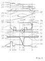
- time profiles of different signals are plotted, wherein a signal curve 19 visualizes a driver-request-dependent desired gear, wherein a signal curve 20 visualizes a target gear determined on the basis of the target gear, wherein a signal curve 21 visualizes an actual gear, wherein a signal curve 22 a torque of the drive unit 1 of the drive train and a waveform 23, a speed of the drive unit 1 visualized.
- the waveforms 24, 25, 26, 27 and 28 visualize the control or the temporal behavior of five involved in the interleaved execution of two successive downshifts switching elements, the waveform 24, the temporal behavior of a first to be opened during the first downshift and thus disconnected first Visualized the switching element, the waveform 25 visualizes the temporal behavior of the first downshift to be closed and thus zuzupillar second switching element, the waveform 26 visualizes the temporal behavior of the third switch element to be prepared during the first downshift for the subsequent second downshift to open and thus shutdown , and wherein the waveform 27, the temporal behavior visualized during the execution of the first downshift for a subsequent second downshift for closing and thus switching to prepare fourth switching element.
- the signal curve 28 visualizes the temporal behavior of a fifth switching element, which is kept closed during the execution of the first upshift or downshift and during the execution of the second upshift or downshift.
- the fifth switching element (see signal curve 28) is kept closed,
- the preparation of the fourth switching element to be closed in a possible subsequent second downshift and thus to be connected takes place with a rapid filling which extends between the times C and E.
- the rapid filling of the fourth switching element at time E the same changes into a filling compensation phase, which lasts until the time G according to FIG. 4.
- the prepared for switching fourth switching element changes from the filling phase in the switching phase.
- the third switch element (see waveform 26) is prepared for opening or shutting down.
- time F a transition phase of the prepared for the subsequent second downshift third and thus the prepared switching off switching element is started, wherein at time S, the one synchronization point of the first downshift corresponds to a change from the first downshift to the subsequent second downshift takes place.
- the switching elements prepared during the first downshift are the active switching elements of the subsequent second downshift.
- the fourth switching element prepared for closing and thus connecting during the first switch-back is the closing switching element of the second reset circuit.
- the switching off in the first downshift and thus opening first switching element is switched off. From time H, the third switching element, which has been prepared for opening or shutting down, reaches the cut-off pressure level.
- the fifth switching element (see waveform 28) is kept closed or approximately closed during the execution of the first downshift and during the execution of the second downshift.
- switching elements are prepared for any subsequent third downshift, which in turn is a single downshift (see waveforms 29 and 30).
- the fourth shift element to be closed during the second downshift (see waveform 27) is prepared for closing at a time C by rapid fill, which is timed or event driven Applicable first time period T 1 before reaching the synchronization point of the current first downshift at time S is.
- the time-controlled or event-controlled applicable first time period T 1 can, for. B. over a time reservation or a differential speed relative to the synchronization point S of the first downshift can be realized.
- the instant C which results from the synchronization point S of the current first downshift and from the administrable first time span T 1 , lies ahead of the end (instant B) of the fast filling phase of the second switching element to be closed during the first downshift, then the Delaying the preparation of the fourth switching element until the fast filling phase of the second switching element to be closed during the first reset is completed,
- the fourth switching element (see signal curve 27) prepared for the second downshift during the execution of the first downshift for closing is transferred from the preparation phase into the switching phase at time G.
- This time G is a time-controlled or event-controlled applicable second time period T 2 before the synchronization point S of the first downshift. Then, as shown in FIG. 4, this time point G, which results from the synchronization point S of the first downshift and the applicable second time period T 2 , occurs after the end of the fast filling phase (time E) of the fourth switching element to be closed during the second downshift is to be closed during the second downshifting fourth switching element is transferred directly from the preparation phase into the switching phase.
- the transition will take place of the fourth switching element from the preparation phase in the switching phase delayed until the fast filling phase of the fourth switching element is completed.
- the third switching element prepared for opening and thus switching off during the execution of the first downshift for the subsequent second downshift is transferred from the preparation phase to the switching phase at time F, this time F being a time span T controlled by a time control or event control 3 before reaching the synchronization point S of the first downshift.
- time F it is decided in the illustrated embodiment whether the second downshift prepared during the first downshift is actually executed.
- a prepared sequential circuit is only executed if this corresponds to a driver's request.
- a further downshift (x-3) is desired at time F according to the signal pattern 19 representing the driver request, so that the second downshift is then actually executed in the example of FIG. 4 becomes.
- corresponding switching elements are prepared during the second downshift for a third subsequent downshift according to the signal curves 29 and 30, wherein in FIG. 4 for the second downshift to be prepared during the second downshift the correspondingly applicable first time period T ' 1 , second time period T ' 2 and third period of time T' 3 are related to a synchronization point S 'of the second downshift.
- the third downshift prepared during execution of the second downshift is a single downshift.
- Fig. 4 it can be seen that at a defined by the synchronization point S 'of the second downshift and the applicable third time T' 3 time based on the driver's request representing waveform 19 for the desired gear no further downshift is desired, so that the during the second downshift prepared third downshift is not executed, but rather is canceled.
- the actual gear is set to a new value each time the synchronization points S and S 'of a running circuit are detected, while the target gear is dependent on the desired gear in accordance with the signal path 20 according to the waveform 19 changes to the next gear or remains unchanged.
- a torque of the drive unit is increased and / or reduced compared to a torque for the drive unit derived from a driver request. so as to support the interleaved execution of the successive downshifts.
- the waveform 22 shown in solid lines in FIG. 4 corresponds to a torque derived from a driver request for the drive unit.
- the moment of the drive unit is increased both during the execution of the first downshift and during the execution of the second downshift against the torque derived from the driver for the drive unit.
- the torque for the drive unit is reduced to the end of the second downshift relative to the torque derived from the driver for the drive unit. Both variants will be discussed in greater detail below.
- a transition between the torque increase of the first downshift and the torque increase of the second downshift is performed, in the embodiment shown, the torque increase of the second downshift is greater than the torque increase of the first downshift. In contrast, it is also possible that the torque increase of the second downshift is smaller than the torque increase of the first downshift. Likewise, both torque increases can be the same size. Between the two torque increases preferably a ramp-like transition is performed.
- two successive downshifts are executed as nested circuits by driving five switching elements, wherein according to FIG. 4, a first switching element (waveform 24) is opened and thus switched off to execute the first downshift as a multiple circuit, and a second switching element (waveform 25) ) is closed and thus switched on.
- the third switching element (signal curve 26) is prepared for opening and thus switching off for the subsequent second downshift, and the fourth switching element (signal curve 27) for closing and so that switching is prepared.
- the fifth switching element (waveform 28) is kept closed during the execution of the first downshift and during the execution of the second downshift.
- the exemplary procedure shown in FIG. 4 by way of example for nested downshifts is. analog transferable to nested upshifts.
- the execution of successive upshifts compared to the execution of successive downshifts shown in FIG. 4 only a difference in the third aspect of the present invention, which relates to the increase or decrease in the torque of the drive unit over a torque derived from a driver request for the drive unit.
Landscapes
- Engineering & Computer Science (AREA)
- General Engineering & Computer Science (AREA)
- Mechanical Engineering (AREA)
- Control Of Transmission Device (AREA)
Applications Claiming Priority (1)
| Application Number | Priority Date | Filing Date | Title |
|---|---|---|---|
| DE102006026605.6A DE102006026605B4 (de) | 2006-06-08 | 2006-06-08 | Verfahren zum Betreiben eines Antriebsstrangs |
Publications (3)
| Publication Number | Publication Date |
|---|---|
| EP1865228A2 true EP1865228A2 (fr) | 2007-12-12 |
| EP1865228A3 EP1865228A3 (fr) | 2011-11-09 |
| EP1865228B1 EP1865228B1 (fr) | 2012-11-14 |
Family
ID=37852861
Family Applications (1)
| Application Number | Title | Priority Date | Filing Date |
|---|---|---|---|
| EP07109572A Active EP1865228B1 (fr) | 2006-06-08 | 2007-06-05 | Procédé destiné au fonctionnement d'une chaîne cinématique |
Country Status (3)
| Country | Link |
|---|---|
| US (1) | US8002669B2 (fr) |
| EP (1) | EP1865228B1 (fr) |
| DE (1) | DE102006026605B4 (fr) |
Families Citing this family (6)
| Publication number | Priority date | Publication date | Assignee | Title |
|---|---|---|---|---|
| DE102006026601A1 (de) * | 2006-06-08 | 2007-12-13 | Zf Friedrichshafen Ag | Verfahren zum Betreiben eines Antriebsstrangs |
| DE102006026602B4 (de) * | 2006-06-08 | 2020-07-09 | Zf Friedrichshafen Ag | Verfahren zum Betreiben eines Antriebsstrangs |
| DE102006026597A1 (de) * | 2006-06-08 | 2007-03-29 | Zf Friedrichshafen Ag | Verfahren zum Betreiben eines Antriebsstrangs |
| WO2014181387A1 (fr) * | 2013-05-07 | 2014-11-13 | トヨタ自動車株式会社 | Dispositif de commande de changement de vitesse pour véhicule |
| US9371065B2 (en) | 2014-03-20 | 2016-06-21 | GM Global Technology Operations LLC | Method of controlling a transmission |
| CN115875445B (zh) * | 2023-02-23 | 2023-05-12 | 北京航空航天大学 | 一种改善车辆动力响应的重叠降挡控制系统和控制方法 |
Citations (3)
| Publication number | Priority date | Publication date | Assignee | Title |
|---|---|---|---|---|
| DE10035479A1 (de) | 2000-07-21 | 2002-02-21 | Zahnradfabrik Friedrichshafen | Verfahren zur Verbesserung der Schaltgeschwindigkeit |
| EP1219868A2 (fr) | 2000-12-28 | 2002-07-03 | Aisin Aw Co., Ltd. | Dispositif de commande de changement de vitesses pour transmission automatique |
| EP1398537A2 (fr) | 2002-09-13 | 2004-03-17 | General Motors Corporation | Famille de transmissions à plusieurs rapports avec deux entrées débrayables |
Family Cites Families (27)
| Publication number | Priority date | Publication date | Assignee | Title |
|---|---|---|---|---|
| DE19918734A1 (de) | 1999-04-24 | 2000-11-16 | Daimler Chrysler Ag | Zahnräderwechselgetriebe mit zwei im Kraftfluß parallel zueinander angeordneten Teilgetrieben |
| US5113343A (en) | 1990-08-02 | 1992-05-12 | General Motors Corporation | Sequenced control of double transition powered downshifting in an automatic transmission |
| DE19928674B4 (de) | 1999-06-23 | 2004-04-22 | Zf Friedrichshafen Ag | Steuerung einer Überschneidungsschaltung nach einem vorgegebenen Abtriebsmoment |
| DE19963752A1 (de) | 1999-12-30 | 2001-07-12 | Bosch Gmbh Robert | Verfahren und Vorrichtung zur Steuerung eines Schaltvorgangs bei Kraftfahrzeugen mit einem sequentiell schaltenden Automatikgetriebe |
| US6623397B1 (en) | 2002-04-17 | 2003-09-23 | General Motors Corporation | Family of multi-speed transmission mechanisms with three non-continuously interconnected planetary gear sets |
| JP3901010B2 (ja) | 2002-05-17 | 2007-04-04 | アイシン・エィ・ダブリュ株式会社 | 自動変速機の変速制御装置 |
| JP3841018B2 (ja) * | 2002-05-20 | 2006-11-01 | アイシン・エィ・ダブリュ株式会社 | 自動変速機の変速制御装置 |
| US6577939B1 (en) * | 2002-05-20 | 2003-06-10 | Ford Global Technologies, Llc | Pressure control system and control method for a multiple-ratio transmission with pre-staged ratio shifts |
| US6746362B2 (en) | 2002-09-12 | 2004-06-08 | General Motors Corporation | Six speed planetary transmission mechanisms with two fixed interconnections |
| GB2415022B (en) | 2003-04-28 | 2007-07-25 | Volkswagen Ag | Drive transmission |
| DE10330153A1 (de) | 2003-07-04 | 2005-02-03 | Zf Friedrichshafen Ag | Verfahren zur Verbesserung der Schaltgeschwindigkeit für Automatgetriebe |
| DE10338624A1 (de) * | 2003-08-22 | 2004-11-25 | Daimlerchrysler Ag | Verfahren zur Durchführung einer Mehrfachschaltung eines automatischen Stufengetriebes eines Kraftfahrzeugs |
| JP4305098B2 (ja) | 2003-09-02 | 2009-07-29 | トヨタ自動車株式会社 | 3摩擦係合要素同時係合型変速装置 |
| JP4272039B2 (ja) | 2003-11-21 | 2009-06-03 | ジヤトコ株式会社 | 自動変速機用歯車変速装置 |
| DE10361288A1 (de) * | 2003-12-24 | 2005-07-28 | Daimlerchrysler Ag | Vorrichtung mit einer Steuer- und/oder Regeleinheit |
| DE102004001381A1 (de) | 2004-01-09 | 2005-08-04 | Zf Friedrichshafen Ag | Verfahren zur Erhöhung der Spontanität von Überschneidungsschaltungen in einem Automatgetriebe |
| DE102004001380B4 (de) * | 2004-01-09 | 2014-12-11 | Zf Friedrichshafen Ag | Verfahren zur Verbesserung der Schaltgeschwindigkeit |
| DE102004010269A1 (de) | 2004-03-03 | 2005-09-22 | Zf Friedrichshafen Ag | Verfahren zur Gestaltung der Schaltgeschwindigkeit von Automatgetrieben |
| DE102005008383B4 (de) | 2004-03-09 | 2013-09-05 | Schaeffler Technologies AG & Co. KG | Betätigungseinrichtung für ein automatisiertes Getriebe |
| KR100579302B1 (ko) | 2004-06-21 | 2006-05-11 | 현대자동차주식회사 | 차량용 다단 자동 변속기 |
| DE102004040611B4 (de) | 2004-08-21 | 2015-11-26 | Zf Friedrichshafen Ag | Mehrstufengetriebe |
| US7150696B2 (en) | 2004-08-24 | 2006-12-19 | General Motors Corporation | Planetary transmissions having a stationary gear member and clutched input members |
| DE102004041507A1 (de) * | 2004-08-27 | 2006-03-16 | Zf Friedrichshafen Ag | Mehrstufengetriebe |
| DE102004043345A1 (de) | 2004-09-08 | 2006-03-30 | Zf Friedrichshafen Ag | Verfahren zum Steuern und Regeln eines Automatgetriebes |
| JP4461997B2 (ja) * | 2004-10-12 | 2010-05-12 | 日産自動車株式会社 | エンジンの制御装置 |
| DE102006026604A1 (de) * | 2006-06-08 | 2007-03-29 | Zf Friedrichshafen Ag | Verfahren zum Betreiben eines Antriebsstrangs |
| DE102006026606B4 (de) * | 2006-06-08 | 2021-06-24 | Zf Friedrichshafen Ag | Verfahren zum Betreiben eines Antriebsstrangs |
-
2006
- 2006-06-08 DE DE102006026605.6A patent/DE102006026605B4/de active Active
-
2007
- 2007-06-05 EP EP07109572A patent/EP1865228B1/fr active Active
- 2007-06-07 US US11/811,440 patent/US8002669B2/en active Active
Patent Citations (3)
| Publication number | Priority date | Publication date | Assignee | Title |
|---|---|---|---|---|
| DE10035479A1 (de) | 2000-07-21 | 2002-02-21 | Zahnradfabrik Friedrichshafen | Verfahren zur Verbesserung der Schaltgeschwindigkeit |
| EP1219868A2 (fr) | 2000-12-28 | 2002-07-03 | Aisin Aw Co., Ltd. | Dispositif de commande de changement de vitesses pour transmission automatique |
| EP1398537A2 (fr) | 2002-09-13 | 2004-03-17 | General Motors Corporation | Famille de transmissions à plusieurs rapports avec deux entrées débrayables |
Also Published As
| Publication number | Publication date |
|---|---|
| US8002669B2 (en) | 2011-08-23 |
| EP1865228B1 (fr) | 2012-11-14 |
| DE102006026605B4 (de) | 2022-03-31 |
| EP1865228A3 (fr) | 2011-11-09 |
| US20070287586A1 (en) | 2007-12-13 |
| DE102006026605A1 (de) | 2007-04-05 |
Similar Documents
| Publication | Publication Date | Title |
|---|---|---|
| EP1865232B1 (fr) | Procédé destiné au fonctionnement dýune chaîne cinématique | |
| EP1865234B1 (fr) | Procédé destiné au fonctionnement dýune chaîne cinématique | |
| EP0478945B1 (fr) | Procédé de changement de vitesse automatique d'une transmission à roues dentées à positions multiples au moyen d'assistance par pression | |
| EP1865231B1 (fr) | Procédé destiné au fonctionnement d'une chaîne cinématique | |
| DE10035479B4 (de) | Verfahren zur Verbesserung der Schaltgeschwindigkeit | |
| DE10218734B4 (de) | Schaltsteuervorrichtung eines Automatikgetriebes | |
| EP1865229B1 (fr) | Procédé destiné au fonctionnement d'une chaîne cinématique | |
| WO2008113688A2 (fr) | Procédé permettant de faire fonctionner une boîte de vitesses automatique | |
| DE102010000859A1 (de) | Verfahren zum Betreiben einer Getriebevorrichtung mit mehreren reibschlüssigen Schaltelementen und wenigstens einem formschlüssigen Schaltelement | |
| EP2652365B1 (fr) | Procédé permettant de faire fonctionner un dispositif de transmission de la chaîne cinématique d'un véhicule, comportant au moins un élément de changement de vitesse à complémentarité de forme et plusieurs éléments de changement de vitesse à friction | |
| EP1865233B1 (fr) | Procédé destiné au fonctionnement dýune chaîne cinématique | |
| EP2457794A2 (fr) | Procédé destiné au fonctionnement d'une chaîne cinématique | |
| EP1865228B1 (fr) | Procédé destiné au fonctionnement d'une chaîne cinématique | |
| DE102010040455A1 (de) | Verfahren zum Betreiben eines Antriebsstrangs | |
| EP2524157B1 (fr) | Procédé pour faire fonctionner une chaîne cinématique de véhicule à moteur comprenant un moteur à combustion interne | |
| DE102004043345A1 (de) | Verfahren zum Steuern und Regeln eines Automatgetriebes | |
| EP1865230B1 (fr) | Procédé destiné au fonctionnement d'une boîte de vitesse automatique | |
| EP1543259A2 (fr) | Accroissement de la spontaneite d'une boite de vitesses automatique | |
| DE102006026596A1 (de) | Verfahren zum Betreiben eines Antriebsstrangs | |
| EP0814286B1 (fr) | Méthode de commande de changement de vitesse d'une transmission automatique de véhicule automobile | |
| DE102006026601A1 (de) | Verfahren zum Betreiben eines Antriebsstrangs | |
| DE4138080C2 (de) | Verfahren zur Steuerung eines automatischen Kraftfahrzeuggetriebes | |
| AT517581B1 (de) | Verfahren zur durchführung von schaltvorgängen in einem fahrzeugantriebsstrang | |
| DE102006001899A1 (de) | Verfahren zur Adaption verschachtelter Schaltungen | |
| DE102009028150A1 (de) | Verfahren zum Betreiben eines Antriebsstrangs |
Legal Events
| Date | Code | Title | Description |
|---|---|---|---|
| PUAI | Public reference made under article 153(3) epc to a published international application that has entered the european phase |
Free format text: ORIGINAL CODE: 0009012 |
|
| AK | Designated contracting states |
Kind code of ref document: A2 Designated state(s): AT BE BG CH CY CZ DE DK EE ES FI FR GB GR HU IE IS IT LI LT LU LV MC MT NL PL PT RO SE SI SK TR |
|
| AX | Request for extension of the european patent |
Extension state: AL BA HR MK YU |
|
| PUAL | Search report despatched |
Free format text: ORIGINAL CODE: 0009013 |
|
| AK | Designated contracting states |
Kind code of ref document: A3 Designated state(s): AT BE BG CH CY CZ DE DK EE ES FI FR GB GR HU IE IS IT LI LT LU LV MC MT NL PL PT RO SE SI SK TR |
|
| AX | Request for extension of the european patent |
Extension state: AL BA HR MK RS |
|
| RIC1 | Information provided on ipc code assigned before grant |
Ipc: F16H 61/04 20060101AFI20110930BHEP Ipc: F16H 61/686 20060101ALN20110930BHEP |
|
| 17P | Request for examination filed |
Effective date: 20111205 |
|
| RIC1 | Information provided on ipc code assigned before grant |
Ipc: F16H 61/04 20060101AFI20120425BHEP Ipc: F16H 61/686 20060101ALN20120425BHEP |
|
| GRAP | Despatch of communication of intention to grant a patent |
Free format text: ORIGINAL CODE: EPIDOSNIGR1 |
|
| GRAJ | Information related to disapproval of communication of intention to grant by the applicant or resumption of examination proceedings by the epo deleted |
Free format text: ORIGINAL CODE: EPIDOSDIGR1 |
|
| GRAP | Despatch of communication of intention to grant a patent |
Free format text: ORIGINAL CODE: EPIDOSNIGR1 |
|
| AKX | Designation fees paid |
Designated state(s): AT BE BG CH CY CZ DE DK EE ES FI FR GB GR HU IE IS IT LI LT LU LV MC MT NL PL PT RO SE SI SK TR |
|
| RIC1 | Information provided on ipc code assigned before grant |
Ipc: F16H 61/686 20060101ALN20120626BHEP Ipc: F16H 61/04 20060101AFI20120626BHEP |
|
| GRAS | Grant fee paid |
Free format text: ORIGINAL CODE: EPIDOSNIGR3 |
|
| GRAA | (expected) grant |
Free format text: ORIGINAL CODE: 0009210 |
|
| AK | Designated contracting states |
Kind code of ref document: B1 Designated state(s): AT BE BG CH CY CZ DE DK EE ES FI FR GB GR HU IE IS IT LI LT LU LV MC MT NL PL PT RO SE SI SK TR |
|
| REG | Reference to a national code |
Ref country code: GB Ref legal event code: FG4D Free format text: NOT ENGLISH |
|
| REG | Reference to a national code |
Ref country code: AT Ref legal event code: REF Ref document number: 584179 Country of ref document: AT Kind code of ref document: T Effective date: 20121115 Ref country code: CH Ref legal event code: EP |
|
| REG | Reference to a national code |
Ref country code: IE Ref legal event code: FG4D Free format text: LANGUAGE OF EP DOCUMENT: GERMAN |
|
| REG | Reference to a national code |
Ref country code: DE Ref legal event code: R096 Ref document number: 502007010853 Country of ref document: DE Effective date: 20130110 |
|
| REG | Reference to a national code |
Ref country code: NL Ref legal event code: VDEP Effective date: 20121114 |
|
| REG | Reference to a national code |
Ref country code: LT Ref legal event code: MG4D |
|
| PG25 | Lapsed in a contracting state [announced via postgrant information from national office to epo] |
Ref country code: LT Free format text: LAPSE BECAUSE OF FAILURE TO SUBMIT A TRANSLATION OF THE DESCRIPTION OR TO PAY THE FEE WITHIN THE PRESCRIBED TIME-LIMIT Effective date: 20121114 Ref country code: ES Free format text: LAPSE BECAUSE OF FAILURE TO SUBMIT A TRANSLATION OF THE DESCRIPTION OR TO PAY THE FEE WITHIN THE PRESCRIBED TIME-LIMIT Effective date: 20130225 Ref country code: FI Free format text: LAPSE BECAUSE OF FAILURE TO SUBMIT A TRANSLATION OF THE DESCRIPTION OR TO PAY THE FEE WITHIN THE PRESCRIBED TIME-LIMIT Effective date: 20121114 Ref country code: SE Free format text: LAPSE BECAUSE OF FAILURE TO SUBMIT A TRANSLATION OF THE DESCRIPTION OR TO PAY THE FEE WITHIN THE PRESCRIBED TIME-LIMIT Effective date: 20121114 |
|
| PG25 | Lapsed in a contracting state [announced via postgrant information from national office to epo] |
Ref country code: LV Free format text: LAPSE BECAUSE OF FAILURE TO SUBMIT A TRANSLATION OF THE DESCRIPTION OR TO PAY THE FEE WITHIN THE PRESCRIBED TIME-LIMIT Effective date: 20121114 Ref country code: SI Free format text: LAPSE BECAUSE OF FAILURE TO SUBMIT A TRANSLATION OF THE DESCRIPTION OR TO PAY THE FEE WITHIN THE PRESCRIBED TIME-LIMIT Effective date: 20121114 Ref country code: PT Free format text: LAPSE BECAUSE OF FAILURE TO SUBMIT A TRANSLATION OF THE DESCRIPTION OR TO PAY THE FEE WITHIN THE PRESCRIBED TIME-LIMIT Effective date: 20130314 Ref country code: GR Free format text: LAPSE BECAUSE OF FAILURE TO SUBMIT A TRANSLATION OF THE DESCRIPTION OR TO PAY THE FEE WITHIN THE PRESCRIBED TIME-LIMIT Effective date: 20130215 Ref country code: PL Free format text: LAPSE BECAUSE OF FAILURE TO SUBMIT A TRANSLATION OF THE DESCRIPTION OR TO PAY THE FEE WITHIN THE PRESCRIBED TIME-LIMIT Effective date: 20121114 |
|
| PG25 | Lapsed in a contracting state [announced via postgrant information from national office to epo] |
Ref country code: DK Free format text: LAPSE BECAUSE OF FAILURE TO SUBMIT A TRANSLATION OF THE DESCRIPTION OR TO PAY THE FEE WITHIN THE PRESCRIBED TIME-LIMIT Effective date: 20121114 Ref country code: CZ Free format text: LAPSE BECAUSE OF FAILURE TO SUBMIT A TRANSLATION OF THE DESCRIPTION OR TO PAY THE FEE WITHIN THE PRESCRIBED TIME-LIMIT Effective date: 20121114 Ref country code: BG Free format text: LAPSE BECAUSE OF FAILURE TO SUBMIT A TRANSLATION OF THE DESCRIPTION OR TO PAY THE FEE WITHIN THE PRESCRIBED TIME-LIMIT Effective date: 20130214 Ref country code: SK Free format text: LAPSE BECAUSE OF FAILURE TO SUBMIT A TRANSLATION OF THE DESCRIPTION OR TO PAY THE FEE WITHIN THE PRESCRIBED TIME-LIMIT Effective date: 20121114 Ref country code: EE Free format text: LAPSE BECAUSE OF FAILURE TO SUBMIT A TRANSLATION OF THE DESCRIPTION OR TO PAY THE FEE WITHIN THE PRESCRIBED TIME-LIMIT Effective date: 20121114 |
|
| PG25 | Lapsed in a contracting state [announced via postgrant information from national office to epo] |
Ref country code: RO Free format text: LAPSE BECAUSE OF FAILURE TO SUBMIT A TRANSLATION OF THE DESCRIPTION OR TO PAY THE FEE WITHIN THE PRESCRIBED TIME-LIMIT Effective date: 20121114 Ref country code: NL Free format text: LAPSE BECAUSE OF FAILURE TO SUBMIT A TRANSLATION OF THE DESCRIPTION OR TO PAY THE FEE WITHIN THE PRESCRIBED TIME-LIMIT Effective date: 20121114 Ref country code: IT Free format text: LAPSE BECAUSE OF FAILURE TO SUBMIT A TRANSLATION OF THE DESCRIPTION OR TO PAY THE FEE WITHIN THE PRESCRIBED TIME-LIMIT Effective date: 20121114 |
|
| PLBE | No opposition filed within time limit |
Free format text: ORIGINAL CODE: 0009261 |
|
| STAA | Information on the status of an ep patent application or granted ep patent |
Free format text: STATUS: NO OPPOSITION FILED WITHIN TIME LIMIT |
|
| 26N | No opposition filed |
Effective date: 20130815 |
|
| PG25 | Lapsed in a contracting state [announced via postgrant information from national office to epo] |
Ref country code: CY Free format text: LAPSE BECAUSE OF FAILURE TO SUBMIT A TRANSLATION OF THE DESCRIPTION OR TO PAY THE FEE WITHIN THE PRESCRIBED TIME-LIMIT Effective date: 20121114 |
|
| REG | Reference to a national code |
Ref country code: DE Ref legal event code: R097 Ref document number: 502007010853 Country of ref document: DE Effective date: 20130815 |
|
| BERE | Be: lapsed |
Owner name: ZF FRIEDRICHSHAFEN A.G. Effective date: 20130630 |
|
| PG25 | Lapsed in a contracting state [announced via postgrant information from national office to epo] |
Ref country code: MC Free format text: LAPSE BECAUSE OF FAILURE TO SUBMIT A TRANSLATION OF THE DESCRIPTION OR TO PAY THE FEE WITHIN THE PRESCRIBED TIME-LIMIT Effective date: 20121114 |
|
| REG | Reference to a national code |
Ref country code: CH Ref legal event code: PL |
|
| GBPC | Gb: european patent ceased through non-payment of renewal fee |
Effective date: 20130605 |
|
| REG | Reference to a national code |
Ref country code: IE Ref legal event code: MM4A |
|
| PG25 | Lapsed in a contracting state [announced via postgrant information from national office to epo] |
Ref country code: BE Free format text: LAPSE BECAUSE OF NON-PAYMENT OF DUE FEES Effective date: 20130630 |
|
| PG25 | Lapsed in a contracting state [announced via postgrant information from national office to epo] |
Ref country code: CH Free format text: LAPSE BECAUSE OF NON-PAYMENT OF DUE FEES Effective date: 20130630 Ref country code: GB Free format text: LAPSE BECAUSE OF NON-PAYMENT OF DUE FEES Effective date: 20130605 Ref country code: IE Free format text: LAPSE BECAUSE OF NON-PAYMENT OF DUE FEES Effective date: 20130605 Ref country code: LI Free format text: LAPSE BECAUSE OF NON-PAYMENT OF DUE FEES Effective date: 20130630 |
|
| REG | Reference to a national code |
Ref country code: AT Ref legal event code: MM01 Ref document number: 584179 Country of ref document: AT Kind code of ref document: T Effective date: 20130605 |
|
| PG25 | Lapsed in a contracting state [announced via postgrant information from national office to epo] |
Ref country code: AT Free format text: LAPSE BECAUSE OF NON-PAYMENT OF DUE FEES Effective date: 20130605 |
|
| PG25 | Lapsed in a contracting state [announced via postgrant information from national office to epo] |
Ref country code: MT Free format text: LAPSE BECAUSE OF FAILURE TO SUBMIT A TRANSLATION OF THE DESCRIPTION OR TO PAY THE FEE WITHIN THE PRESCRIBED TIME-LIMIT Effective date: 20121114 |
|
| PG25 | Lapsed in a contracting state [announced via postgrant information from national office to epo] |
Ref country code: TR Free format text: LAPSE BECAUSE OF FAILURE TO SUBMIT A TRANSLATION OF THE DESCRIPTION OR TO PAY THE FEE WITHIN THE PRESCRIBED TIME-LIMIT Effective date: 20121114 |
|
| PG25 | Lapsed in a contracting state [announced via postgrant information from national office to epo] |
Ref country code: LU Free format text: LAPSE BECAUSE OF NON-PAYMENT OF DUE FEES Effective date: 20130605 Ref country code: HU Free format text: LAPSE BECAUSE OF FAILURE TO SUBMIT A TRANSLATION OF THE DESCRIPTION OR TO PAY THE FEE WITHIN THE PRESCRIBED TIME-LIMIT; INVALID AB INITIO Effective date: 20070605 |
|
| REG | Reference to a national code |
Ref country code: FR Ref legal event code: PLFP Year of fee payment: 10 |
|
| PG25 | Lapsed in a contracting state [announced via postgrant information from national office to epo] |
Ref country code: IS Free format text: LAPSE BECAUSE OF FAILURE TO SUBMIT A TRANSLATION OF THE DESCRIPTION OR TO PAY THE FEE WITHIN THE PRESCRIBED TIME-LIMIT Effective date: 20121114 |
|
| REG | Reference to a national code |
Ref country code: FR Ref legal event code: PLFP Year of fee payment: 11 |
|
| REG | Reference to a national code |
Ref country code: FR Ref legal event code: PLFP Year of fee payment: 12 |
|
| REG | Reference to a national code |
Ref country code: FR Ref legal event code: PLFP Year of fee payment: 17 |
|
| P01 | Opt-out of the competence of the unified patent court (upc) registered |
Effective date: 20230528 |
|
| PGFP | Annual fee paid to national office [announced via postgrant information from national office to epo] |
Ref country code: DE Payment date: 20250402 Year of fee payment: 19 |
|
| PGFP | Annual fee paid to national office [announced via postgrant information from national office to epo] |
Ref country code: FR Payment date: 20250401 Year of fee payment: 19 |